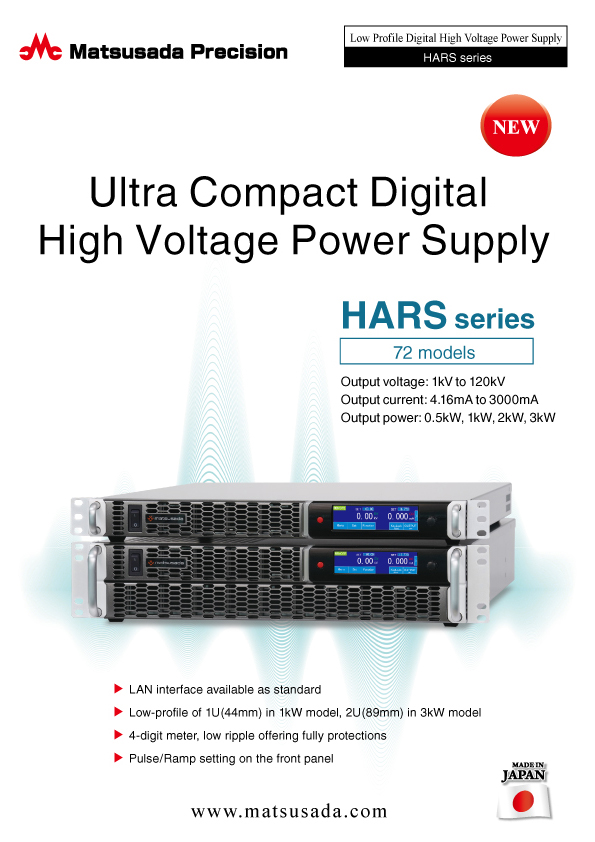
Rack Mount DC 0.5-3 kW Digital High Voltage Power Supply
- 1 kV to 120 kV
4.16 mA to 3000 mA
0.5kW, 1kW, 2kW, 3kW 
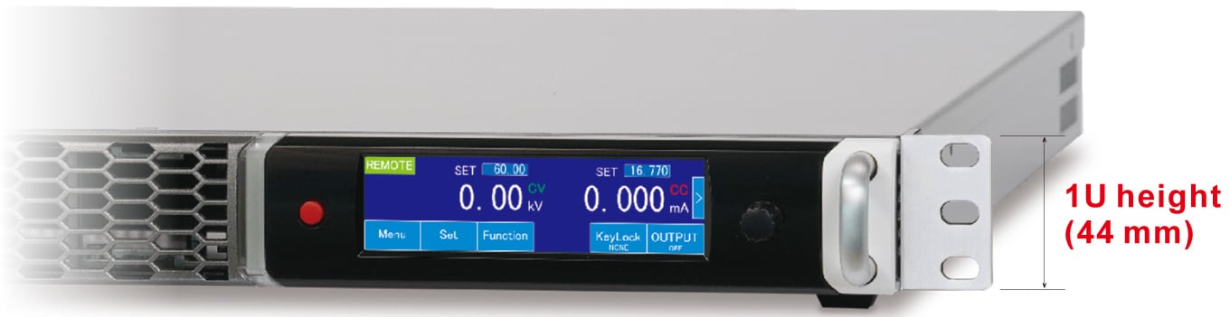
Compact:
19 inches (44 mm)
Low Ripple:
0.05%p-p
Advanced Remote
Functions
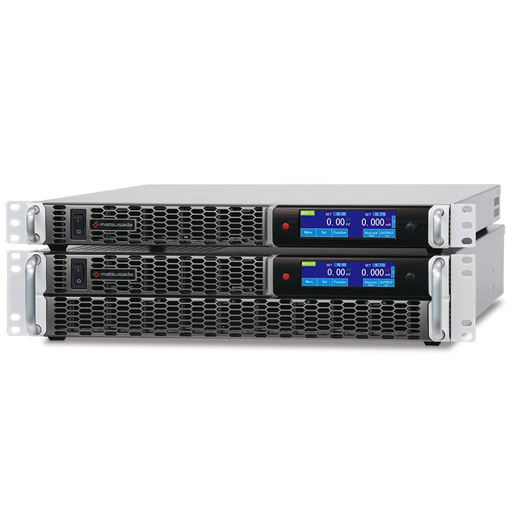
Reliable High-Voltage Power in a Space-Saving Design
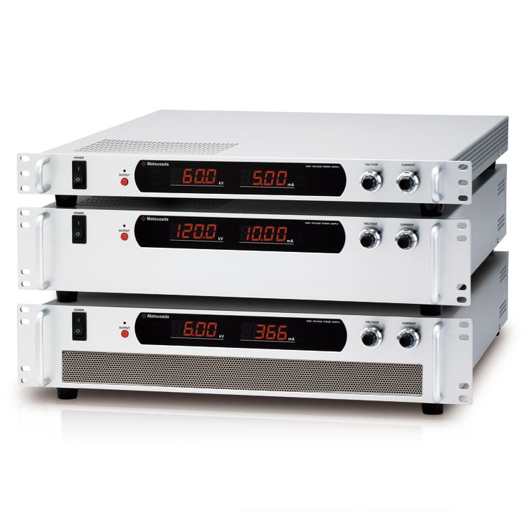
The HARS series of 19-inch (1U) rack-mount high-voltage power supplies delivers exceptional stability and reliability in a space-saving 1U design. Available with outputs ranging from 500 W to 3 kW, each model features a digital interface, arc count protection, and extensive remote-control functionality, making it ideal for demanding industrial and research applications.
FEATURES AND BENEFITS
-
1. Compact Design for Space Efficiency
1U (44 mm) Rack-mount Chassis
Engineered for high-voltage applications requiring a low profile, the HARS series maximizes space efficiency without compromising performance.
This compact form factor is ideal for integration into inspection systems, production lines, and other equipment where space is limited.
(Models 1 kV to 60 kV/1 kW or lower)
-
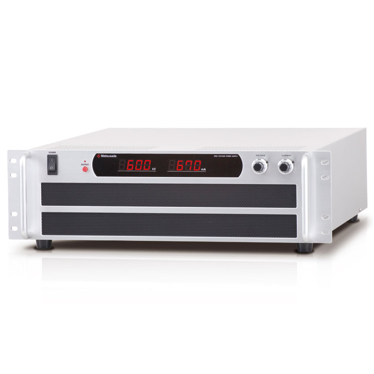
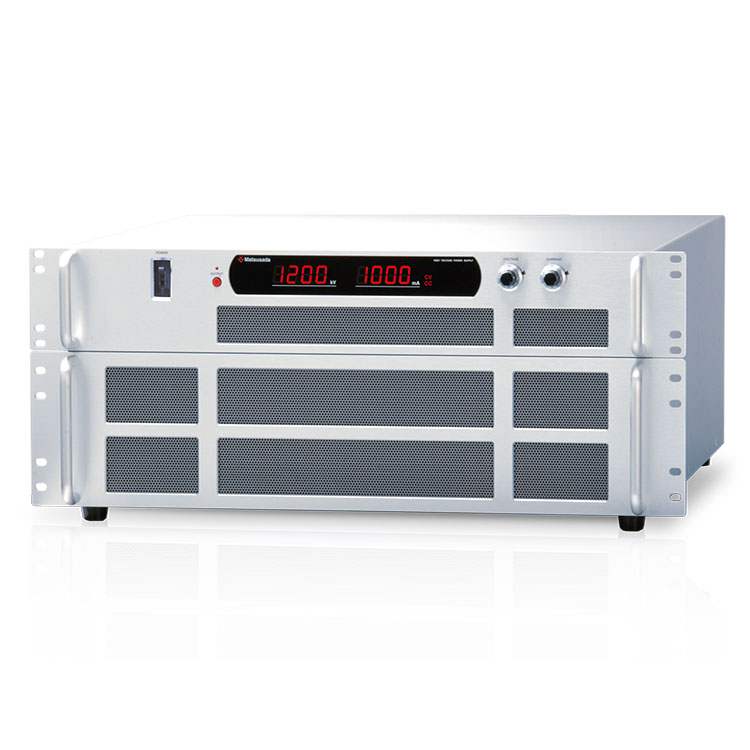
2. Broad Lineup for Diverse Applications
To meet specific application requirements, the HARS series offers a wide selection of voltage and power configurations, with an output voltage range from 1 kV to 120 kV.
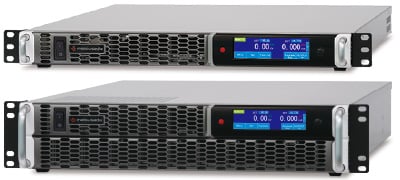
*Actual model image may vary
-
3. Standard Digital Interfaces
Designed for automated test equipment (ATE) and system integration, the HARS series includes standard digital interfaces to streamline control and monitoring.
Standard: LAN (30 kV models and below) and USB (10 kV models and below).
Optional interfaces include RS-232C, RS-485, and Optical. GPIB control is also available via a separate digital controller adapter. -
4. Reliability and Safety
Safety is paramount in high-voltage applications. The HARS series is equipped with comprehensive protection features, including interlock, arc protection, and variable Over Voltage Protection (OVP) and Over Current Protection (OCP). These functions ensure safe operation and protect the load from unexpected surges.
-
5. Low Ripple Performance (0.05%p-p)
With low ripple noise—less than half that of the HAR series—this series is optimized for precision applications requiring stable output, such as electron beams, ion beams, and detectors.
Applications
- High Voltage Material Testing
- Measure Power Device Leakage
- Unit Test of Property Change
- Development of inverters
- Capacitor Charging
- Dielectric Withstand Test
- Electron Beam and Ion Beam
- X-Ray System
- Electrospinning (formation of ultra-fine polymer fibers)
- Evaluation of inverter
Models
| Model | Maximum Output | Size | Digital interface | |||
|---|---|---|---|---|---|---|
| Voltage | Current | Power | Standard | Option | ||
| HARS-1P500 | 1 kV | 500 mA | 500 W | 1U | LAN/USB | -LGob -LRs |
| HARS-1P1000 | 1 kV | 1000 mA | 1000 W | 1U | ||
| HARS-1P2000 | 1 kV | 2000 mA | 2000 W | 2U | ||
| HARS-1P3000 | 1 kV | 3000 mA | 3000 W | 2U | ||
| HARS-1.5P333 | 1.5 kV | 333 mA | 500 W | 1U | ||
| HARS-1.5P666 | 1.5 kV | 666 mA | 1000 W | 1U | ||
| HARS-1.5P1333 | 1.5 kV | 1333 mA | 2000 W | 2U | ||
| HARS-1.5P2000 | 1.5 kV | 2000 mA | 3000 W | 2U | ||
| HARS-3P166 | 3 kV | 166 mA | 500 W | 1U | ||
| HARS-3P333 | 3 kV | 333 mA | 1000 W | 1U | ||
| HARS-3P666 | 3 kV | 666 mA | 2000 W | 2U | ||
| HARS-3P1000 | 3 kV | 1000 mA | 3000 W | 2U | ||
| HARS-6P83.3 | 6 kV | 83.3 mA | 500 W | 1U | ||
| HARS-6P166 | 6 kV | 166 mA | 1000 W | 1U | ||
| HARS-6P333 | 6 kV | 333 mA | 2000 W | 2U | ||
| HARS-6P500 | 6 kV | 500 mA | 3000 W | 2U | ||
| HARS-10P50 | 10 kV | 50 mA | 500 W | 1U | ||
| HARS-10P100 | 10 kV | 100 mA | 1000 W | 1U | ||
| HARS-10P200 | 10 kV | 200 mA | 2000 W | 2U | ||
| HARS-10P300 | 10 kV | 300 mA | 3000 W | 2U | ||
| HARS-30P16.6 | 30 kV | 16.6 mA | 500 W | 1U | LAN | -LGob |
| HARS-30P33.3 | 30 kV | 33.3 mA | 1000 W | 1U | ||
| HARS-30P66.6 | 30 kV | 66.6 mA | 2000 W | 2U | ||
| HARS-30P100 | 30 kV | 100 mA | 3000 W | 2U | ||
| HARS-60P8.33 | 60 kV | 8.33 mA | 500 W | 1U | -- | |
| HARS-60P16.6 | 60 kV | 16.6 mA | 1000 W | 1U | ||
| HARS-60P33.3 | 60 kV | 33.3 mA | 2000 W | 2U | ||
| HARS-60P50 | 60 kV | 50 mA | 3000 W | 2U | ||
| HARS-100P5 | 100 kV | 5 mA | 500 W | 2U | ||
| HARS-100P10 | 100 kV | 10 mA | 1000 W | 2U | ||
| HARS-100P20 | 100 kV | 20 mA | 2000 W | 2U | ||
| HARS-100P30 | 100 kV | 30 mA | 3000 W | 2U | ||
| HARS-120P4.16 | 120 kV | 4.16 mA | 500 W | 2U | ||
| HARS-120P8.33 | 120 kV | 8.33 mA | 1000 W | 2U | ||
| HARS-120P16.6 | 120 kV | 16.6 mA | 2000 W | 2U | ||
| HARS-120P25 | 120 kV | 25 mA | 3000 W | 2U | ||
| Model | Maximum Output | Size | Interface | |||
|---|---|---|---|---|---|---|
| Voltage | Current | Power | Standard | Option | ||
| HARS-1N500 | -1 kV | 500 mA | 500 W | 1U | LAN/USB | -LGob -LRs |
| HARS-1N1000 | -1 kV | 1000 mA | 1000 W | 1U | ||
| HARS-1N2000 | -1 kV | 2000 mA | 2000 W | 2U | ||
| HARS-1N3000 | -1 kV | 3000 mA | 3000 W | 2U | ||
| HARS-1.5N333 | -1.5 kV | 333 mA | 500 W | 1U | ||
| HARS-1.5N666 | -1.5 kV | 666 mA | 1000 W | 1U | ||
| HARS-1.5N1333 | -1.5 kV | 1333 mA | 2000 W | 2U | ||
| HARS-1.5N2000 | -1.5 kV | 2000 mA | 3000 W | 2U | ||
| HARS-3N166 | -3 kV | 166 mA | 500 W | 1U | ||
| HARS-3N333 | -3 kV | 333 mA | 1000 W | 1U | ||
| HARS-3N666 | -3 kV | 666 mA | 2000 W | 2U | ||
| HARS-3N1000 | -3 kV | 1000 mA | 3000 W | 2U | ||
| HARS-6N83.3 | -6 kV | 83.3 mA | 500 W | 1U | ||
| HARS-6N166 | -6 kV | 166 mA | 1000 W | 1U | ||
| HARS-6N333 | -6 kV | 333 mA | 2000 W | 2U | ||
| HARS-6N500 | -6 kV | 500 mA | 3000 W | 2U | ||
| HARS-10N50 | -10 kV | 50 mA | 500 W | 1U | ||
| HARS-10N100 | -10 kV | 100 mA | 1000 W | 1U | ||
| HARS-10N200 | -10 kV | 200 mA | 2000 W | 2U | ||
| HARS-10N300 | -10 kV | 300 mA | 3000 W | 2U | ||
| HARS-30N16.6 | -30 kV | 16.6 mA | 500 W | 1U | LAN | LAN |
| HARS-30N33.3 | -30 kV | 33.3 mA | 1000 W | 1U | ||
| HARS-30N66.6 | -30 kV | 66.6 mA | 2000 W | 2U | ||
| HARS-30N100 | -30 kV | 100 mA | 3000 W | 2U | ||
| HARS-60N8.33 | -60 kV | 8.33 mA | 500 W | 1U | -- | |
| HARS-60N16.6 | -60 kV | 16.6 mA | 1000 W | 1U | ||
| HARS-60N33.3 | -60 kV | 33.3 mA | 2000 W | 2U | ||
| HARS-60N50 | -60 kV | 50 mA | 3000 W | 2U | ||
| HARS-100N5 | -100 kV | 5 mA | 500 W | 2U | ||
| HARS-100N10 | -100 kV | 10 mA | 1000 W | 2U | ||
| HARS-100N20 | -100 kV | 20 mA | 2000 W | 2U | ||
| HARS-100N30 | -100 kV | 30 mA | 3000 W | 2U | ||
| HARS-120N4.16 | -120 kV | 4.16 mA | 500 W | 2U | ||
| HARS-120N8.33 | -120 kV | 8.33 mA | 1000 W | 2U | ||
| HARS-120N16.6 | -120 kV | 16.6 mA | 2000 W | 2U | ||
| HARS-120N25 | -120 kV | 25 mA | 3000 W | 2U | ||
Functions
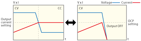
 Flexible Current Limit and Protection: CC Control & OCP turn-off SYSTEM
The HARS series offers both Constant Current (CC) control and Overcurrent Protection (OCP). By configuring the set points for each, you can define the desired behavior. Set the CC level to actively limit the current by voltage droop, or set the OCP threshold to cut off the output completely for protection. This dual-functionality provides flexible and reliable control over the output current.
 Protection by Arc Trip
Arc discharge count Protection
The HARS series makes it easy to protect your power supplies with its advanced arc count & monitoring function.
There are two methods to set the output stop:
-
(1) Arc Protect Count:
The output is turned off when the output current surpasses the arc count limit.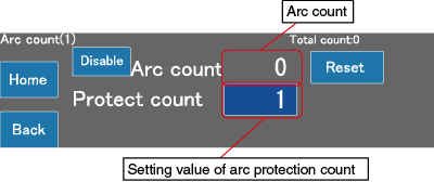
Arc count (1) setting screen Maximum arc count: 9999
-
(2) Arc Protect Count and Time:
The output is turned off when the output current surpasses the arc count limit within a defined time frame.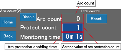
Arc count (2) setting screen Maximum arc count: 999
Maximum of arc protection enabling time: 59 m 59 s
 Pulse and Ramp Sequence Functions
Program output patterns without a computer
* Note: The output cannot follow the set value if the programmed time is shorter than the unit's rise time (Tr) or fall time (Tf).
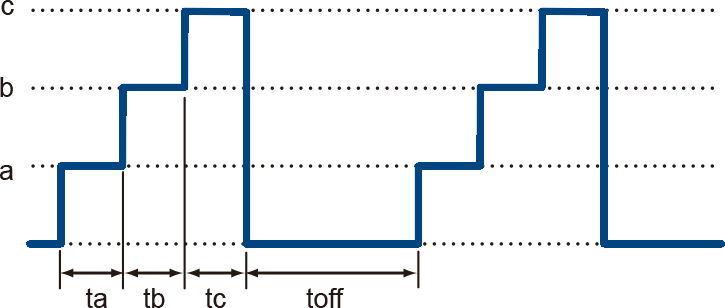
A. Pulse (Step) Sequence
The Sequence function allows users to program voltage and current patterns by cycling through settings stored in memories a, b, and c. The sequence can run continuously or for a specified number of cycles. This eliminates the need for external computer control during simple repetitive tests.
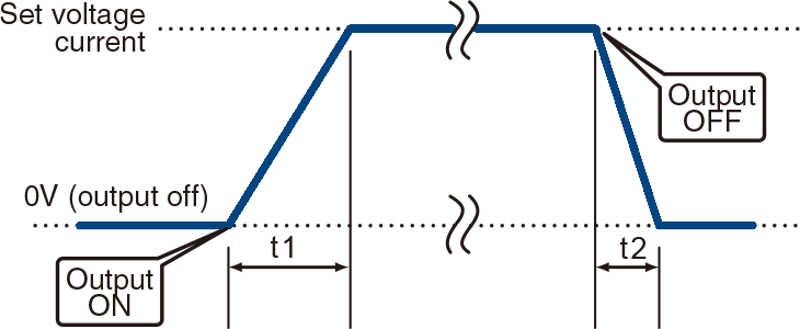
B. Ramp Function
The Ramp function linearly increases or decreases the output to a set voltage or current over a specified time (t1, t2). This is essential for applications requiring gradual power-up or power-down to protect the load.
* Ramp operation targets: Voltage & Current, Voltage Only, or Current Only.
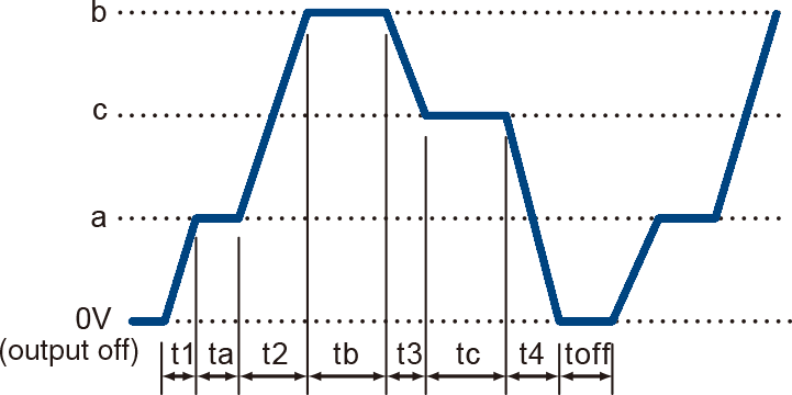
C. Combined Sequence and Ramp
For advanced control, the Sequence and Ramp functions can be used together. This allows you to create complex profiles by smoothly ramping the voltage and/or current between the discrete steps defined in memories a, b, and c. The entire waveform can be run continuously or for a pre-set number of cycles, making it a powerful tool for various testing scenarios.
External analog remote control
-
External output ON/OFF
The output can be turned ON/OFF by relay or TTL signal. -
Remote/Local change
As for the output voltage control, output current control, overvoltage protection, and overcurrent protection, the remote/local mode can be individually switched by relay or TTL signal. -
Output monitor (Voltage, Current)
-
Output control (Voltage, Current, Overvoltage protection, Overcurrent protection)
-
Status output
Specifications
- Input voltage
- 100 to 240 Vac, 50/60 Hz, Single-phase
200 to 240 Vac, 50/60 Hz, Three-phase
207 to 253 Vac, 50/60 Hz, Single-phase (option) - Output voltage control
-
[Local] Rotary encoder on front panel
[Analog remote] External control voltage 0 to 10 Vdc or external 10kΩ potentiometer
[Digital remote] Command - Output current control
-
[Local] Rotary encoder on front panel
[Analog remote] External control voltage 0 to 10 Vdc or external 10kΩ potentiometer
[Digital remote] Command
HARS Series Options
Select the option that works best for your enterprise.
-LF
Floating Ground
For measuring the current in load. (Able to withstand voltage of 50 Vdc)
For devices that connect to a Remote control connector (TB1), -LF requires floating ground.
*This option cannot be used to float the high voltage power supply itself.
-LGob*
Optical Interface Port
This option provides an optical interface port for isolated communication. Optical fiber ensures complete electrical isolation between the power supply and the controller, preventing malfunctions caused by transient surges, lightning induction, and external noise.

- -LGob: Optical Interface port + Optical cable 2 meters
- -LGob(Fc5): Optical Interface port + Optical cable 5 meters
- -LGob(Fc10): Optical Interface port + Optical cable 10 meters
- -LGob(Fc20): Optical Interface port + Optical cable 20 meters
- -LGob(Fc40): Optical Interface port + Optical cable 40 meters
Select the optical interface option (-LGob) for the following conditions:
- Noisy environments, such as factories with motors or coils operating near the power supply or load.
- Installations where the distance between the power supply and controller (PC/PLC) exceeds 2 meters.
- Applications with a high risk of arcing or output short-circuits.
A separate adapter (CO/USB series) is required for control via digital interface.
-LRs*
RS-232C/RS-485 interface port
(only 10 kV or less models)
Using RS-232C/RS-485 communications, output controlling and operation status monitoring of these devices can be performed.

-L(230V1P)
Single-phase input
(2000 W or more models)
-L(0m)
Without output cable
Output cable not provided.
If you require a cable longer than 2.5 meters, please select this option and purchase an output cable separately.
*Only one option may be chosen at this time.
How to Order
When placing an order, please add the option code(s) after the model name. If adding two or more options, omit the “-L” from the second and subsequent option codes, and list them in alphabetical order, with the parentheses option placed at the end.
Example: HARS-1P500-LFRs, HARS-1P500-LFGob(Fc10)(0m)
Accessories
Optical isolation adapter
Adapters for connecting optical interface port
This option changes the standard interfaces to a built-in optical interface port. By combining this option with an adapter for optical connection (sold separately), communication between the control device and the power supply can be controlled in an isolated state. Be sure to select this option when using the product in the following environments.
- CO-E32: LAN to optical interface adapter
- USB-OPT: USB to optical interface adapter
- CO-OPT2-9: RS-232C (9-pin) to optical interface adapter
- CO-OPT2-25: RS-232C (25-pin) to optical interface adapter
- CO-OPT4-25: RS-485 (25-pin) to optical interface adapter
- CO-G32: GPIB to optical interface adapter (Discontinued in December 2028)

For details, refer to CO/USB series
AC input cable
|
Sold separately 1000 W or less models (input voltage 100 Vac) |
CABLE TYPE8 |  |
 |
2.5 meters Fixed length |
|---|---|---|---|---|
|
Sold separately 1000 W or less models (input voltage 200 Vac) |
CABLE TYPE3 | |
 Flying lead |
2.5 meters Fixed length |
|
Sold separately 2000 W or more models (three-phase) |
CABLE TYPE6 |  |
 Flying lead |
2.5 meters (specified length available) |
|
-L(230V1P) option Sold separately 2000 W or more models (single-phase) |
CABLE TYPE5 |  |
 Flying lead |
2.5 meters (specified length available) |
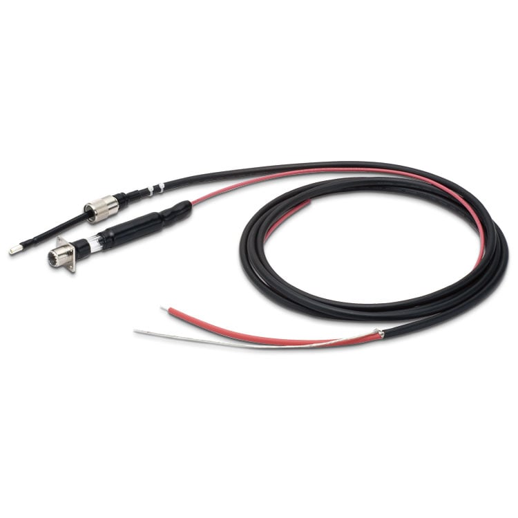
High voltage output cable
| Standard [Models all in 500 W and 1000 W, Models 3 kV to 120 kV in 2000 W and 3000 W] |
CN-15-MHVP (1kV to 10 kV models) |

|
2.5 meters |
|---|---|---|---|
| CN-30-MHVP (30 kV model) |

|
||
| CN-60-MHVP (60 kV model) |

|
||
| CN-120AR-MHVP (100 kV and 120 kV models) |

|
||
| Standard [kV and 1.5 kV models in 2000 W to 3000 W] |
CN-15PR-MHVP |

|
2.5 meters |
If you need a cable other than 2.5-meter length, please select option -L(0m) and purchase our output cable separately.
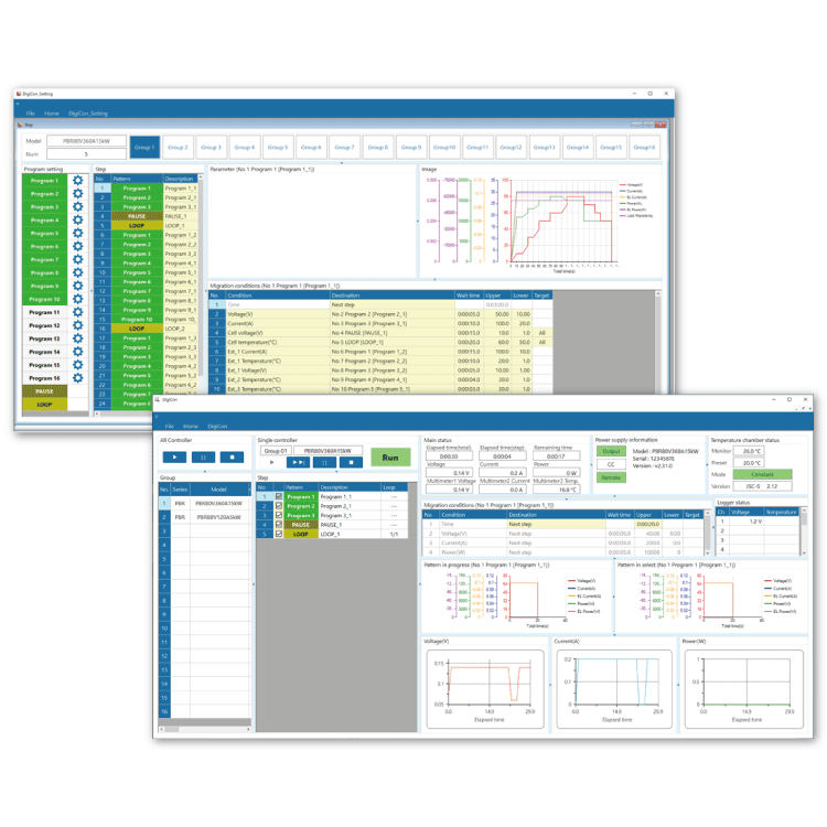
Application software
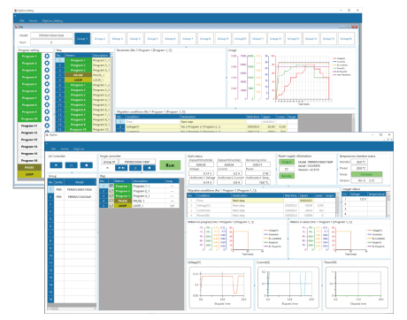
DigiCon-HARS: Remote control, Test workflow design, and Data logging
DigiCon is an application software that remotely controls Matsusada Precision's DC power supplies connected via LAN. The software can control multiple power supplies simultaneously or individually.
- Power control for PRKT, PRT/PRTM, PBR/PBRM, P4KF, PKTS, HARS series
- Full remote control available
- Consists of "configuration software" and "operation software
- Linkage to digital multimeters, data loggers, and thermostatic chambers is possible.
- Easy operation with Graphical User Interface (GUI)
- Automatic Test Equipment (ATE) can be built without programming knowledge.
- Real-time logging, graphing, and data storage
Dimensions
Download
If you are unable to download a file
Please try the following solution.
- Please press Ctrl+F5 to clear the cache of your web browser and try again.
- Please restart your web browser and log in again to try again.
- Please change your web browser to another browser and try again.
- Restart the computer and try again.
- Please try again on a different computer.
-
HARS series Datasheet
Date: 2025-10-28 rev 18
PDF (3,220 KB)
-
Safety and Usage of High voltage Power supply
Date: 2025-09-08 rev 04
PDF (602 KB)
-
High Performance High Voltage Power Supplies
Date: 2026-02-09 rev 13
PDF (4,555 KB)

-
HARS series Instruction Manual
Date: 2024-04-23 rev 0.5
PDF (2,428KB)
-
DigiCon Instruction Manual
Date: 2025-03-25 rev 0.2
PDF (4,541 KB)

-
HARS series Outline Drawing (DXF, PDF)
Date: 2024-07-31
ZIP (666 KB)
-
HARS series (60kV or less/1kW or less models) 3D MODELS (STEP, IGES)
Date: 2025-05-15
ZIP (7,689 KB)
-
HARS series (60kV or less/2kW to 3kW models) 3D MODELS (STEP, IGES)
Date: 2025-05-15
ZIP (17,119 KB)
-
HARS series (100kV to 120kV/1kW or less models) 3D MODELS (STEP, IGES)
Date: 2025-05-15
ZIP (16,233 KB)
Login Required
-
HARS series Datasheet
Date: 2025-10-28 rev 18
PDF (3,220 KB)
-
Safety and Usage of High voltage Power supply
Date: 2025-09-08 rev 04
PDF (602 KB)
-
High Performance High Voltage Power Supplies
Date: 2026-02-09 rev 13
PDF (4,555 KB)
-
HARS series Instruction Manual
Date: 2024-04-23 rev 0.5
PDF (2,428KB)
-
DigiCon Instruction Manual
Date: 2025-03-25 rev 0.2
PDF (4,541 KB)
-
HARS series Outline Drawing (DXF, PDF)
Date: 2024-07-31
ZIP (666 KB)
-
HARS series (60kV or less/1kW or less models) 3D MODELS (STEP, IGES)
Date: 2025-05-15
ZIP (7,689 KB)
-
HARS series (60kV or less/2kW to 3kW models) 3D MODELS (STEP, IGES)
Date: 2025-05-15
ZIP (17,119 KB)
-
HARS series (100kV to 120kV/1kW or less models) 3D MODELS (STEP, IGES)
Date: 2025-05-15
ZIP (16,233 KB)
On this website, we provide only the latest versions of information and instruction manuals for our products. Therefore, the newest versions of manuals on the website may differ from those that came with products you purchased in the past.