


Power Supply Requirements for Laboratory Analyzers
This article discusses the power supply requirements for various laboratory analyzers and scientific instruments. While the functions of these systems vary, they share critical requirements regarding power stability and noise suppression.
Broadly, analyzers can be classified into the following categories:
- Electrochemical analyzers
- Optical analyzers
- Electromagnetic analyzers
- Separation analyzers
- Thermal analyzers and measurement devices
- Other measurement instruments
1. Electrochemical Analyzers: These generally fall into two categories: devices that measure electric current or potential (e.g., potentiometric titrators, pH meters) and those that detect fluorescence using photodiodes (e.g., fluorescent residual oxygen meters).
2. Optical and Electromagnetic Analyzers: These instruments measure electromagnetic waves or electron beams (including secondary X-rays) using various photodetectors.
3. Separation, Thermal, and Other Analyzers: Like electrochemical analyzers, these devices measure physical properties--such as fluorescence, light absorption, stress, or thermal conductivity--by converting them into electrical signals (current or voltage). These analog signals are then digitized via A/D conversion. Because these signals are often weak, minimizing voltage noise and ripple from the power supply is critical to maintaining measurement accuracy.
We focus primarily on equipment that detects electromagnetic radiation (light) or electron beams using photodetectors, as these systems require exceptionally stable power supplies.
Stability of the Radiation Source
A common feature of these analyzers is the use of a radiation source, such as electron beams, X-rays, lasers, UV, visible light, or infrared. The stability of this source is paramount; any fluctuation in the power supply voltage can cause variations in the source's intensity (brightness). These variations directly result in measurement errors. Therefore, high-stability, low-ripple power supplies are essential to prevent the degradation of observation accuracy.
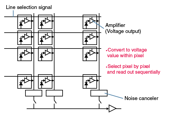
Furthermore, stability is also required in the detectors. Photomultiplier tube (PMT), avalanche photodiode (APD), and photodiodes such as PIN, CCD, and CMOS also convert charges based on the energy and number of photons received by the device into voltage. Therefore, if the power supply is not stable during this voltage conversion, the observation results, such as resolution, would be adversely affected.
Denoising
To stabilize the power supply and obtain a measurement result with a small error margin, the following aspects need to be considered:
- Thermal noise
- Leakage magnetic field
- Electromagnetic interference (EMI)
First, we consider the effects of thermal noise. Thermal noise refers to noise generated by irregular thermal vibrations of free electrons in circuit elements, such as resistors and transistors, due to external thermal energy. Regardless of the magnitude of the voltage, the noise increases in proportion to the absolute temperature. Therefore, an effective countermeasure is "circuit cooling". Incidentally, thermal noise is also called Johnson noise or Johnson Nyquist noise, after the names of the researchers John Johnson and Harry Nyquist who discovered this phenomenon in 1927.
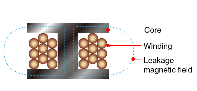
Leakage magnetic fields occur when magnetic flux generated by the internal windings (coils) of a power supply escapes into the surrounding environment. This can induce noise in nearby sensitive components.
Open Magnetic Circuit Structure (Unshielded)
Without shielding, leakage magnetic fields can magnetically couple with other coils or wiring patterns, causing significant noise interference.
Closed Magnetic Circuit Structure (Fully Shielded)
By using a closed magnetic circuit structure--such as a resin shield, full metal shield, or toroidal design--magnetic flux is contained within the core, significantly reducing leakage.
Placement Considerations ideally, power supplies should be isolated from radiation sources and detectors. However, for compact equipment where the power supply must be placed near sensitive components, utilizing a closed magnetic circuit structure is mandatory to prevent interference.
Open magnetic circuit structure
Unshielded
Closed magnetic circuit structure
Fully-shielded
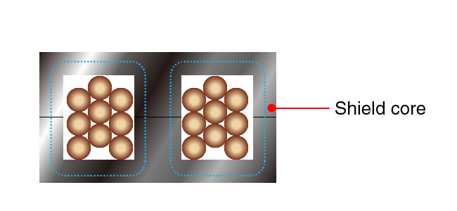
The magnetic flux returns to the shield core, reducing the leakage magnetic field.
As shown in the figure, this can be improved by creating a closed magnetic circuit structure by using a resin shield, full shield, or integrally molded metal. It is desirable to design equipment that does not place a power supply near the radiation source or detector. If compact equipment, which is easily affected by magnetic fields, is placed near the power supply, it is necessary to incorporate a closed magnetic circuit structure.
Electromagnetic interference (EMI) can be broadly divided into "radiation noise" and "conduction noise". In the former, electromagnetic waves are emitted, and in the latter, noise flows through the electrical circuit. For radiated noise, it is necessary to block the spatial conduction of noise. To do so, an object is shielded with a good conductor (or magnetic material) such as metal. In contrast, conduction noise is classified into differential mode noise and common mode noise.
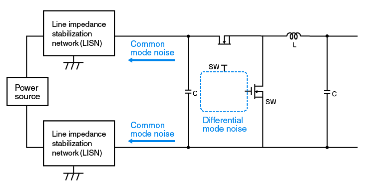
Common mode noise occurs when noise current leaks and returns to the power line via the ground. Unlike differential mode noise, it flows in the same direction on both positive and negative lines. Even with optimized circuit loops, switching noise often manifests as common mode noise. This noise can couple with the signal lines, degrading the signal-to-noise (S/N) ratio. In analytical instruments, this results in reduced resolution, waveform distortion, or the appearance of "ghost peaks."
To mitigate this, high-impedance components like common mode chokes are effective. Since common mode noise also generates radiated noise proportional to cable length, keeping cables short and using proper shielding is crucial.
Environmental Considerations
When integrating power supplies into analyzers, environmental factors such as temperature, humidity, and corrosive atmospheres must be considered.
- Temperature: Operate within specified thermal limits to minimize thermal noise (Johnson noise) and prevent overheating.
- Humidity: High humidity can lead to condensation, causing short circuits or leakage currents.
- Corrosion: Corrosive environments can damage circuits and alter electrical characteristics, leading to unexpected errors or failure.
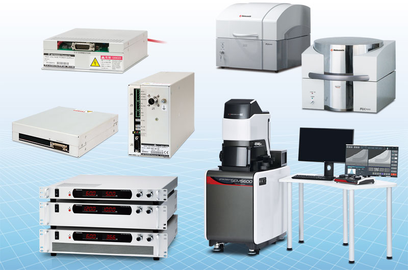
Recommended products
Matsusada Precision manufactures high-performance high-voltage power supplies for analyzers worldwide.


References(Japanese site)
- Japanese source page 「高圧電源の選び方-分析装置編 分析装置の性能と電源性能の関係」
(https://www.matsusada.co.jp/column/hvps1.html) - 分析機器の手引き2017
(https://www.jaima.or.jp/jp/analytical/tebiki/) - 科学機器入門
(https://www.soran.net/guide/index2.html) - 東北大学大学院情報科学研究科 鏡慎吾 「イメージセンサの基礎」
http://www.ic.is.tohoku.ac.jp/~swk/lecture/ic2005/kagami_ic20050419.pdf (non-HTTPS address)