


Electronic Devices Operate on Direct Current
Most electronic devices operate on direct current (DC). This applies to consumer electronics like smartphones, computers, and TVs, as well as automotive components and industrial manufacturing robots. However, different devices--and even different circuits within a single device--require different voltage levels. Since the power supplied from the grid (AC mains) is alternating current, it must be converted to DC and regulated to the precise voltage required for stable circuit operation.
In addition, the alternating current changes voltage with time. Converting from alternating current to direct current will cause the circuit to become unstable due to voltage fluctuations, so conversion to a stable voltage becomes essential.
Conversion from Alternating Current to Stable Direct Current
To obtain a stable DC voltage from an AC source, several steps are required. First, a transformer adjusts the AC voltage level, followed by a rectifier circuit that converts the AC into pulsating DC. Since the output from the rectifier still contains significant voltage fluctuations (ripple), a smoothing circuit--typically using capacitors--is required to filter the waveform closer to a steady DC voltage.

Even after smoothing, the voltage may not be completely stable. To generate the precise DC power required for sensitive electronics, two main regulation methods are used: Linear Power Supplies and Switching Power Supplies.
Linear Power Supply
Linear power supplies function by dropping excess voltage to match the desired output level. A control element acts as a variable resistor, comparing the output voltage to a reference and dissipating the excess energy as heat. While the circuit design is simple and produces very low noise, the heat dissipation results in lower efficiency compared to other methods. Thermal management is critical in these designs.

Switching Power Supply
Switching power supplies regulate voltage by rapidly switching the input on and off using a semiconductor switch, followed by a high-frequency transformer and smoothing circuit. Because this method does not rely on dissipating excess voltage as heat, it is highly efficient. Although switching generates some electronic noise, modern designs effectively minimize this. Switching technology was famously advanced for NASA space applications, where high efficiency is crucial to minimize heat generation in the vacuum of space.

Basics of Linear Power Supplies
As introduced in the previous paragraph, the linear power supply is a method of making DC power while removing extra voltage from AC power. So, you can only get a voltage lower than the original one. Linear power supplies are stabilized, bypassing the control circuit after the smoothing circuit. In this part, it is stabilized by releasing the extra current voltage, which could not be equalized in the smoothing circuit as heat. There are two ways in this circuit. One is a shunt regulator, and the other is a series regulator.
The shunt regulator consists of a resistor (R1) and a Zener diode as a voltage regulator diode (ZD) connected in parallel. When the DC voltage of the output changes, the shunt regulator first converts it to the voltage to be output by the resistor in order to stabilize the voltage and break it up into the current to output and the excess current. The excess current is made to flow to the Zener diode, where it is consumed as heat. When the input voltage fluctuates, the current value coming out of the resistor fluctuates. By making the resistance value of the constant voltage diode variable, stabilization is achieved by making the output current value constant.

On the other hand, in a series regulator, current flows via a transistor (Tr), which is an energy conversion element. The fluctuated voltage is changed constant voltage in this transistor. It is called a series regulator because the transistor is connected in series to the output side. In this case, a reference voltage is required to make the transistor fluctuate so as to maintain a constant voltage. Therefore, the control circuit is connected in parallel to the transistor, which has the same circuit configuration as the shunt regulator, as you can see from the figure. The transistor acts as a variable resistor, dropping the excess voltage to maintain a constant output. This process inevitably generates heat as a byproduct of power dissipation.

Series regulators have the advantage of lower noise and ripple and stability compared to shunt regulators. In any case, the linear power supply has a simple circuit configuration and has the disadvantage of generating heat, but it can produce DC voltage inexpensively.
Basics of Switching Power Supplies
Switching power supplies were developed to overcome the low efficiency and heat generation of linear supplies. They operate by converting the input voltage into a high-frequency pulse waveform--ranging from tens of kHz to several MHz--using a high-speed switch (semiconductor). This high frequency allows for smaller, lighter transformers compared to those used at commercial frequencies (50/60 Hz).

Control methods include PWM (Pulse Width Modulation) and PFM (Pulse Frequency Modulation):
PWM: Controls output by varying the pulse width while keeping the frequency constant. It offers good load response and controlled ripple but maintains switching losses even at light loads.
PFM: Varies the switching frequency. It can offer better efficiency at light loads but may result in variable ripple frequencies that are harder to filter.
Most standard switching power supplies primarily use PWM, while PFM is often employed to improve efficiency during standby or light-load conditions.
Related Technical Articles
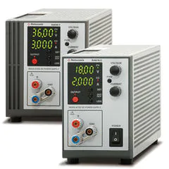
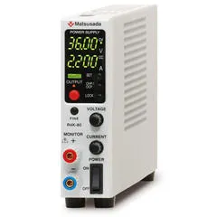
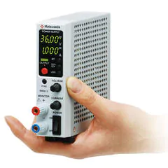
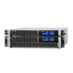
Recommended products
Matsusada Precision offers both series regulator-type DC power supplies and switching-type DC power supplies according to your application.
Reference (Japanese site)
- Japanese source page 「直流電源の作り方 ~交流から直流への変換~」
(https://www.matsusada.co.jp/column/column-dc-power.html) - 「トコトンやさしい電源回路の本」相良岩男著 日刊工業新聞社刊, 2014年
(https://pub.nikkan.co.jp/book/b10021025.html)