


Basics of AC Power Supply
In Japan, the "2018 Hokkaido Eastern Iburi Earthquake" that occurred on September 6, 2018, and typhoon No. 15 in 2019 brought about a "blackout" that caused the power supply to completely stop. Due to these factors, the power plants or the electric wires were damaged, making it impossible to supply electricity for a long time.
In modern society, almost every machine, from home appliances to industrial equipment, needs a power supply. Therefore, the power companies are working day and night for a stable supply of AC power.
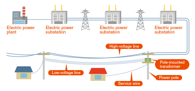
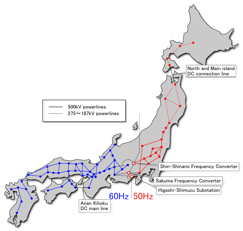
The AC power is transmitted at 60 Hz in western Japan and 50 Hz in eastern Japan. Naturally, power cannot be exchanged as it is between areas with different frequencies. Therefore, power will be exchanged through facilities that perform frequency conversion.
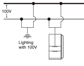
There are also several types of voltage in Japan. For home use, 100 V of single-phase standard voltage (single-phase two-wire system) is mainly used.
Single-phase AC two-wire connection type
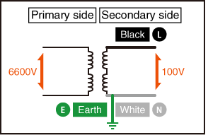
- Green: E (Earth)
- Black: L (Live)
- White: N (Neutral) for earth grounding
Single phase: AC power is transmitted through two electric cables.
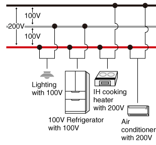
But some devices operate with 200 V of single-phase three-wire system. Recently, the number of single-phase voltage doubler used for air conditioners and the like has been increasing.
Single-phase AC three-wire connection type
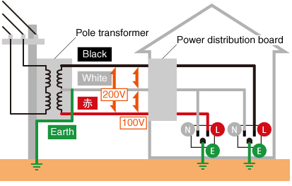
- Green: E (Earth)
- Black: L (Live)
- White: N (Neutral) for earth grounding
Single phase: AC power is transmitted through three electric cables.
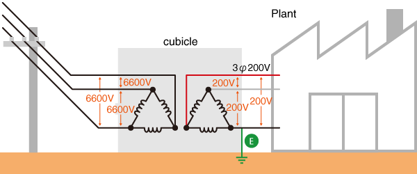
On the other hand, three-phase AC power such as 400V is generally used in factories. In Japan, three-phase AC 200V is often used.
Three-phase electric power
While this is the current situation in Japan, the other countries are largely different. The frequency is 50 Hz or 60 Hz, but the voltage changes.
Cubicle: High-Voltage Power Receiving Equipment (In Japan, this is called a cubicle)
A slightly different example would be the power supply used in aircraft avionics systems. Previously, 14 V or 28 V DC was used, but due to the increase in size and computerization, 400 Hz AC is now used except for some small machines. This higher frequency is used because it is lighter in weight when making a transformer.
The following is a list of single-phase AC voltage, frequency, and shape types used in countries and regions around the world.
| Types | Type A | Type B | Type C | Type D | Type E | Type F | Type G |
|---|---|---|---|---|---|---|---|
| Name in Japan | Type A | Type A | Type C | Type B3 | Type SE | Type SE | Type BF |
| Plugs shapes |  |
 |
 |
 |
 |
 |
 |
| Outlet shapes |  |
 |
 |
 |
 |
 |
 |
| Types | Type H | Type I | Type J | Type K | Type L | Universal | |
| Name in Japan | - | Type O2 | - | - | - | Universal | |
| Plugs shapes |  |
 |
 |
 |
 |
- | |
| Outlet shapes |  |
 |
 |
 |
 |
 |
|
| Area | Countries / Regions | Single-Phase Voltage [V] | Three-Phase Voltage [V] | Frequency [Hz] | Outlet Shape |
|---|---|---|---|---|---|
| Asia | Japan | 100 / 200 V | 200 V | 50/60 Hz | A/B |
| China | 220 V | 380 V | 50 Hz | A/C/I | |
| Hong Kong | 220 V | 380 V | 50 Hz | D/G | |
| Taiwan | 110 V | 220 V | 60 Hz | A/B | |
| South Korea | 220 V | 380 V | 60 Hz | C/F | |
| India | 230 V | 400 V | 50 Hz | C/D/M | |
| Indonesia | 230 V | 400 V | 50 Hz | C/F | |
| Cambodia | 230 V | 400 V | 50 Hz | A/C/G | |
| Singapore | 230 V | 400 V | 50 Hz | C/G/M | |
| Sri Lanka | 230 V | 400 V | 50 Hz | D/G/M | |
| Thailand | 230 V | 400 V | 50 Hz | A/B/C/F/O | |
| Nepal | 230 V | 400 V | 50 Hz | C/D/M | |
| Vietnam | 220 V | 380 V | 50 Hz | A/C/D | |
| Malaysia | 240 V | 415 V | 50 Hz | G | |
| Myanmar | 230 V | 400 V | 50 Hz | C/D/F/G | |
| Laos | 230 V | 400 V | 50 Hz | A/B/C/E/F | |
| Europe | Iceland | 230 V | 400 V | 50 Hz | C/F |
| United Kingdom | 230 V | 415 V | 50 Hz | G | |
| France | 230 V | 400 V | 50 Hz | C/E | |
| Germany | 230 V | 400 V | 50 Hz | C/F | |
| Italy | 230 V | 400 V | 50 Hz | C/F/L | |
| Netherlands | 230 V | 400 V | 50 Hz | C/F | |
| Austria | 230 V | 400 V | 50 Hz | C/F | |
| Greece | 230 V | 400 V | 50 Hz | C/F | |
| Switzerland | 230 V | 400 V | 50 Hz | C/J | |
| Sweden | 230 V | 400 V | 50 Hz | C/F | |
| Spain | 230 V | 400 V | 50 Hz | C/F | |
| Czech Republic | 230 V | 400 V | 50 Hz | C/E | |
| Denmark | 230 V | 400 V | 50 Hz | C/E/F/K | |
| Norway | 230 V | 230 / 400 V | 50 Hz | C/F | |
| Finland | 230 V | 400 V | 50 Hz | C/F | |
| Belgium | 230 V | 400 V | 50 Hz | C/E | |
| Poland | 230 V | 400 V | 50 Hz | C/E | |
| Portugal | 230 V | 400 V | 50 Hz | C/F | |
| Romania | 220 V | 400 V | 50 Hz | C/F | |
| Russia | 220 V | 380 V | 50 Hz | C/F | |
| Middle East | Turkey | 220 V | 400 V | 50 Hz | C/F |
| Israel | 230 V | 400 V | 50 Hz | C/H | |
| Syria | 220 V | 380 V | 50 Hz | C/E/L | |
| Iran | 230 V | 400 V | 50 Hz | C/F | |
| Saudi Arabia | 230 V | 400 V | 60 Hz | G | |
| Jordan | 230 V | 400 V | 50 Hz | C/D/F/G/J | |
| United Arab Emirates (Dubai) | 230 V | 400 V | 50 Hz | G | |
| The Americas | Canada | 120 V | 120 / 208 / 240 / 480 / 347 / 600 V |
60 Hz | A/B |
| United States | 120 V | 208Y/120V, 480Y/277V, 240V Delta |
60 Hz | A/B | |
| Argentina | 220 V | 380 V | 50 Hz | C/I | |
| Ecuador | 120 V | 208 V | 60 Hz | A/B | |
| Cuba | 110 / 220 V | 190 V | 60 Hz | A/B/C/L | |
| Guatemala | 120 V | 208 V | 60 Hz | A/B | |
| Costa Rica | 120 V | 240 V | 60 Hz | A/B | |
| Jamaica | 110 V | 190 V | 50 Hz | A/B | |
| Chile | 220 V | 380 V | 50 Hz | C/L | |
| Panama | 110 V | 240 V | 60 Hz | A/B | |
| Bahamas | 120 V | 208 V | 60 Hz | A/B | |
| Peru | 220 V | 220 V | 60 Hz | A/B/C | |
| Bolivia | 230 V | 400 V | 50 Hz | A/C | |
| Mexico | 127 V | 220 / 480 V | 60 Hz | A/B | |
| Brazil | 127 / 220 V | 220 / 380 V | 60 Hz | C/N | |
| Africa | Egypt | 220 V | 380 V | 50 Hz | C/F |
| Tunisia | 230 V | 400 V | 50 Hz | C/E | |
| Morocco | 220 V | 380 V | 50 Hz | C/E | |
| Kenya | 240 V | 415 V | 50 Hz | G | |
| Zimbabwe | 240 V | 415 V | 50 Hz | D/G | |
| Tanzania | 230 V | 415 V | 50 Hz | D/G | |
| South Africa | 230 V | 400 V | 50 Hz | C/D/M/N | |
| Oceania | Australia | 230 V | 400 V | 50 Hz | I |
| New Caledonia | 220 V | 380 V | 50 Hz | C/F | |
| New Zealand | 230 V | 400 V | 50 Hz | I | |
| Palau | 120 V | 208 V | 60 Hz | A/B | |
| Fiji | 240 V | 415 V | 50 Hz | I | |
| Other | Airplane | 115 / 200 V | - | 400 Hz | - |
| 15A | 20A | 15/20A兼用 | 30A | ||
|---|---|---|---|---|---|
| Single-phase 100V | Ungrounded outlets |
 125V 15A 1500W |
 125V 20A 2000W |
 125V 20A 2000W |
-- |
| Grounded outlets |
 125V 15A 1500W |
 125V 20A 2000W |
 125V 20A 2000W |
-- | |
| Single-phase 200V | Ungrounded outlets |
 250V 15A 3000W |
 250V 20A 4000W |
 250V 30A 6000W |
| Grounded outlets |
 250V 15A 3000W |
 250V 20A 4000W |
-- |
250V 30A 6000W |
|
| Three-phase 200V | Ungrounded outlets |
 250V 15A 5196W |
 250V 20A 6928W |
-- |
 250V 30A 10392W |
| Grounded outlets |
 250V 15A 5196W |
 250V 20A 6928W |
-- |
 250V 30A 10392W |
|
| 15A | 20A | 30A | ||
|---|---|---|---|---|
| Single-phase 100V | Ungrounded outlets |
 125V 15A |
-- | -- |
| Grounded outlets |
 125V 15A |
-- | -- | |
| Single-phase 200V | Ungrounded outlets | -- |
 250V 20A |
 30A |
| Grounded outlets |
 250V 15A |
 250V 20A |
 250V 30A |
|
| Three-phase 200V | Ungrounded outlets | -- |
 250V 20A |
 250V 30A |
| Grounded outlets | -- |
 250V 20A |
-- | |
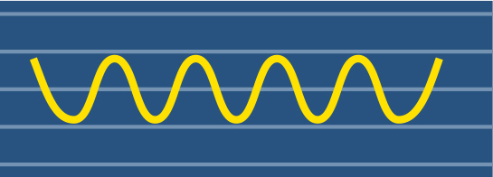
AC waveform trouble
While power companies employ redundant transmission systems to minimize outages, natural disasters and grid load fluctuations make total stability impossible. Beyond complete blackouts, various power quality issues can affect sensitive equipment.
The table below illustrates common voltage waveform anomalies and their characteristics.
| Trouble types | AC Power Waveform | Description | Test by AC Power Supply | Test by Bipolar Power Supply |
|---|---|---|---|---|
| Normal status |
|
A state where stable voltage and frequency are supplied. | Possible* with DRS, DRJ, DRK series | Possible* |
| Power Outage / Blackout |
|
A state where the power supply is stopped for a long time. | Possible* with DRS, DRJ, DRK series | Possible* |
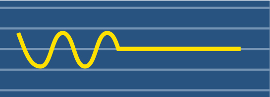
| Instantaneous Power Interruption |
|
A phenomenon in which the power supply stops instantaneously. (The definition of the interruption time varies from a few ms to a few seconds.) | Instantaneously possible* with DRS, DRJ series (DRJ series with an option) | Possible* |
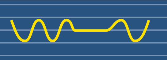
| Voltage Dip / Sag |
|
A phenomenon in which the supply voltage drops instantaneously. | Instantaneously possible* with DRS, DRJ series (DRJ series with an option) | Possible* |
| Voltage Drop / Brownout |
|
A phenomenon in which the voltage temporarily drops. Refers to a sustained drop of tens of milliseconds or more. IEC 61000-4-11 | Simply possible* with DRS, DRJ, DRK series | Possible* |
| Transient/Spike |
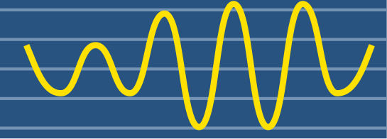
|
Rapid voltage fluctuations caused by switching operations or lightning. | Simulation possible using DRS, DRJ, DRK series | Possible* |
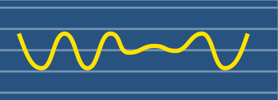
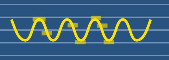
| Voltage fluctuation |
|
A phenomenon in which the voltage fluctuates constantly and periodically. (Flicker) Generally, it is in the range of ± several percent. |
Possible* with DRS, DRJ, DRK series | Possible* |
| Surge |
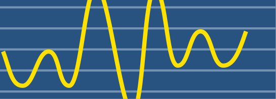
|
Instantaneous high voltage caused by lightning or high power switching. IEC 61000-4-5 |
Not Possible | Not Possible |
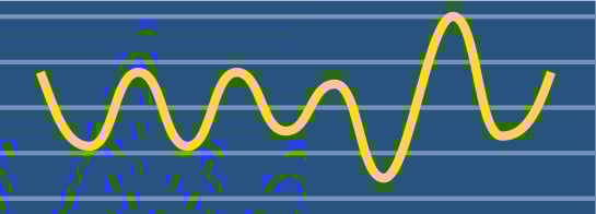
| Noise |
|
A state where high-frequency noise is superimposed on the supply power. IEC 61000-4-4 |
Not Possible | Not Possible |
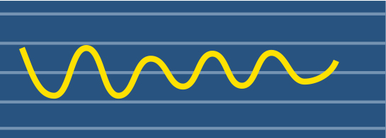
| Frequency fluctuation | 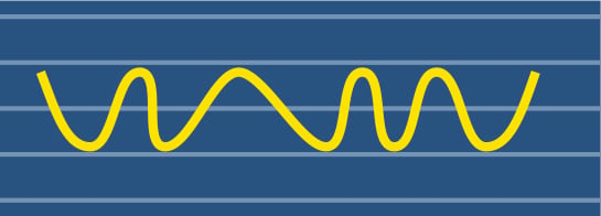 |
A state where the power supply frequency is not constant and fluctuates. Typically, check for stable operation by varying it up to ±2Hz. |
Possible* with DRS, DRJ, DRK series | Possible* |
*Note: Even if the test is listed as "Possible," there may be cases where the test cannot be performed due to limitations of the AC power supply or Bipolar power supply model or its functions.
Among these, Power failure (blackout) refers to the state in which the power supply has been cut off for more than a minute. If it takes less than a minute, it is called a momentary power failure. In particular, if one of the power transmission lines becomes abnormal due to a lightning strike, a momentary voltage drop occurs, and power transmission is temporarily stopped. This is a momentary power failure. In most cases, the power transmission will be resumed within a minute, but if the power transmission cannot be resumed after a minute or more, there will be a state called power failure. Furthermore, "Frequency fluctuation" occurs due to excessive or insufficient power generation on the power generation side.
Even if there is no abnormality in the power grid, there are some troubles that occur only in the home, office, or factory. For example, when a device such as a laser printer that has a high inrush current at startup is connected, the voltage that flows to other devices connected to the same outlet will drop. This is called brownout or voltage drop.
On the other hand, when the power of the device that used a large amount of power is turned off, the voltage flowing to other devices momentarily rises. This is known as a voltage spike or surge. The combination of repeated voltage drops and spikes is referred to as "voltage fluctuation."
In addition, there are phenomena called "Surge" where the voltage rises rapidly due to the influence of lightning from the outside, and "Noise" that occurs in turning ON/OFF devices connected to the same power system.
These troubles could cause visible phenomena including flickering fluorescent light and unstable operation of PC, or problems on manufacturing and R&D.
- Machine operation becomes unstable and reproducibility is lost.
- Control device causes malfunction.
- The accuracy of the test equipment and inspection equipment has deteriorated.
These affect the quality of the product. In the worst case, they also bring down the entire production line. In other words, a stable (AC) power supply is very important.
Types of Programmable AC Power Supplies
To ensure stable operation of precision equipment, various methods are used to stabilize AC power or simulate grid conditions. Below are four common architectures used in AC power sources and stabilizers, along with their respective advantages and disadvantages.
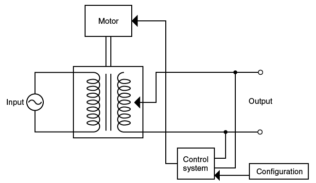
1. Variable Autotransformer Method
This mechanical method uses a servo motor to adjust a variable autotransformer, maintaining a constant output voltage by detecting input fluctuations.
- Advantages: High power conversion efficiency.
- Disadvantages: Slow response time due to mechanical movement; unable to correct waveform distortion or change frequency. The units are typically large and heavy.
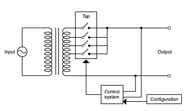
2. Tap-Switching Method
This system utilizes a transformer with multiple taps (e.g., ±5%, ±2%, 0). Semiconductor switches select the appropriate tap based on input voltage fluctuations to regulate the output.
- Advantages: Higher reliability than mechanical autotransformers due to the absence of moving parts.
- Disadvantages: Like autotransformers, this method cannot correct waveform distortion or adjust frequency. The transformer size results in a heavy and bulky unit.
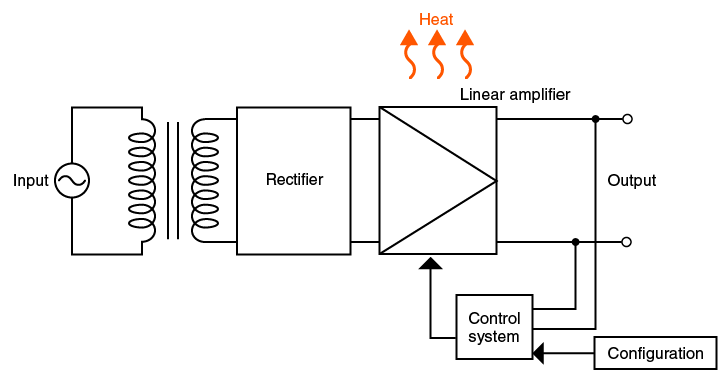
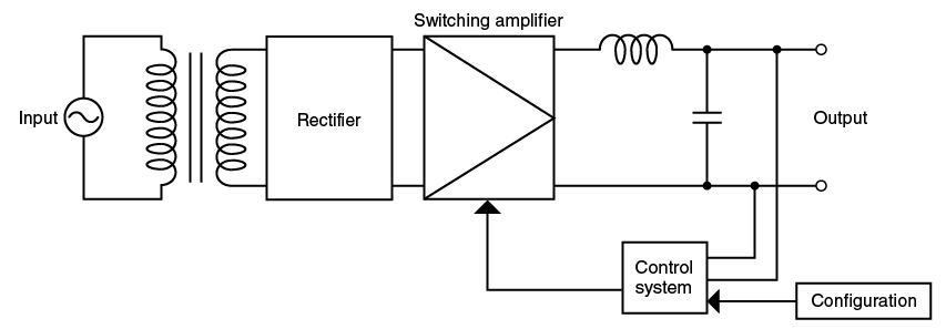
3. Linear Amplifier Method
Unlike simple regulation of input voltage, this method generates a new AC waveform. The input is rectified to DC, and a reference sine wave is amplified using a linear amplifier.
- Advantages: Compact and lightweight design (often 1/3 to 1/4 the weight of linear systems). High efficiency with the ability to freely adjust voltage and frequency.
- Disadvantages: Switching operations may generate higher high-frequency noise compared to linear amplifiers.
- Summary: Due to their compact footprint, PWM models enable benchtop testing in spaces where traditional power supplies would not fit. Selection should be based on specific noise sensitivity requirements.
Using Inverter System
This is an AC power supply that makes the linear amplifier system smaller and lighter, enabling high power. The system is an AC power supply that generates a reference waveform and amplifies it with AMP, similar to the linear amplifier system.
However, the amplification stage is different. The weight and size are reduced to 1/3 to 1/4, by changing the amplification stage from the linear method to the switching method (PWM).
In this way, there is an advantage that it is compact and can output a beautiful sine wave, and the voltage and frequency can be freely changed. Efficiency is also improved by adopting the switching method.
On the other hand, it is disadvantageous that the noise could be larger than the linear method due to switching.
However, due to the size and weight reduction of space, there are some small products that can be placed on a table that could not be used until now, so it is better to select them according to the cases.
While the power supply quality in Japan has become highly stable in recent years, it can be poor in many developing countries. So, AC-stabilized power supplies such as these automatic voltage regulators play an important role in precision equipment that requires stable power supplies.
Related Technical Articles
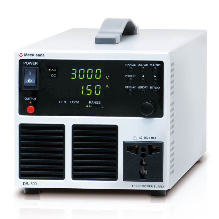
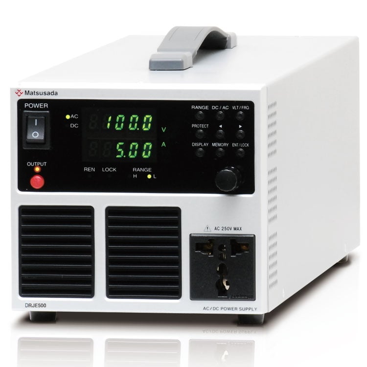
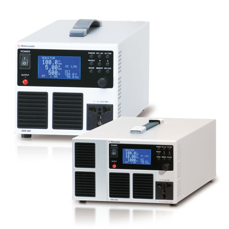
Recommended products
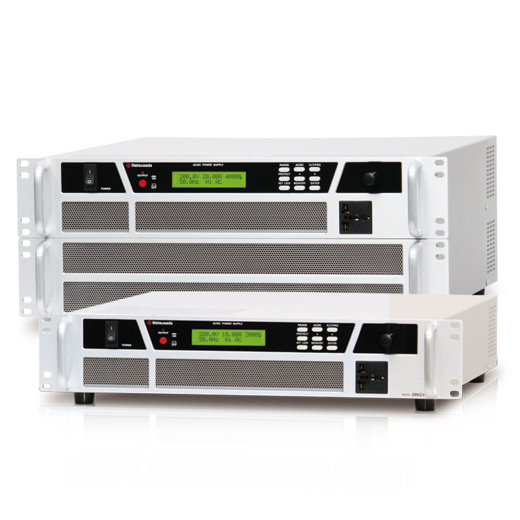
Matsusada Precision's high-performance AC power source
Reference (Japanese site)
- Japanese source page 「安定した交流電源を供給するには」
https://www.matsusada.co.jp/column/ac1910.html(link rot) - 電気の品質「周波数」を一定に保つために
https://www.hepco.co.jp/energy/recyclable_energy/problem/keep_quality.html(link rot) - 世界の電源電圧
http://www.mekatoro.net/digianaecatalog/orien-sougou/Book/orien-sougou-P1787.pdf (non-https address) - 海外旅行に必携!変換プラグ
(https://www.ec-current.com/shop/contents/contents.aspx/00000549) - 航空工学講座10 航空電子・電気装備
(https://book.jaea.or.jp/wp-content/uploads/2022/09/講座10 航空電子電気装備.pdf) - Country Voltage, Frequency, and Plug Type Chart
(https://www.iec.ch/world-plugs)