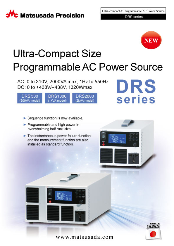
ULTRA-COMPACT SIZE PROGRAMMABLE AC POWER SOURCE
- AC:
0 to 310 V/2000 VA max
1Hz to 550 Hz - DC:
0 to +438 V/-438 V
1320 W max
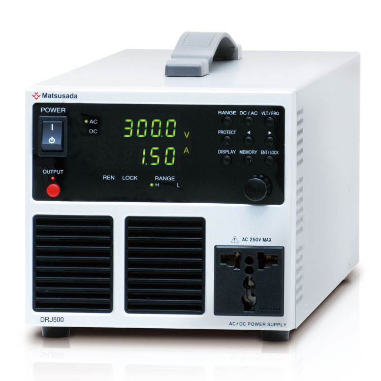
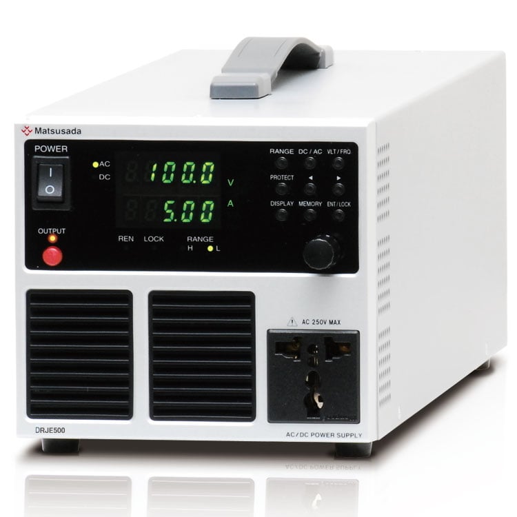
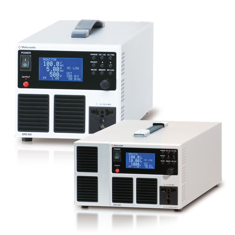
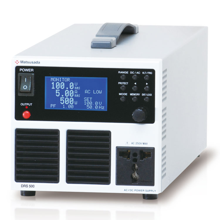
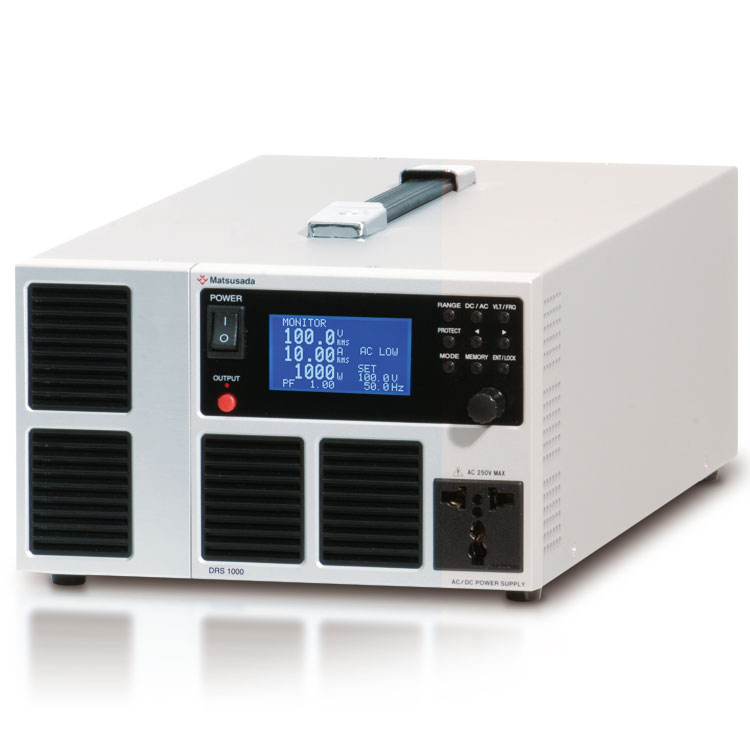
Benchtop High Performance Programmable AC Power Source
The DRS series is a high-performance programmable AC power source that delivers high power density in an exceptionally compact form factor. Designed for R&D, testing, and production lines, the DRS series combines high-quality output with a space-saving footprint. Despite its compact size, it features a universal AC input and a universal output terminal on the front panel, allowing for seamless global operation. Standard features include a momentary power interruption function, a 32-step programmable sequence function, and comprehensive measurement capabilities. This makes the DRS series ideal for testing and evaluating AC input devices under unstable power conditions or momentary power failures.
FEATURES AND BENEFITS
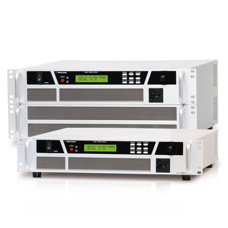
- High power density: Up to 2 kVA in a compact half-rack width (210 mm) chassis (DRS2000).
- Compact and lightweight: significantly smaller and lighter than linear amplifier models due to advanced switching technology.
- Advanced functions standard: Includes momentary power interruption, sequence programming, and measurement functions.
- Wide output range: Supports output voltages up to 155 V / 310 V.
- High peak current capability: Supports peak currents up to four times the rated current (Crest Factor = 4).
- Standard interfaces: Equipped with analog remote control and USB interface (optional interfaces available).
Models
| Model | AC | DC | |||
|---|---|---|---|---|---|
| Lo range (0 to 155 V) |
Hi range (0 to 310 V) |
Lo range (0 to +219 V/0 to -219 V) |
Hi range (0 to +438 V/0 to -438 V) |
||
| DRS500 | Maximum Output Power | 500 VA | 500 VA | 330 W | 330 W |
| Maximum Output Current | 5.00 A | 2.50 A | 2.25 A | 1.10 A | |
| DRS1000 | Maximum Output Power | 1000 VA | 1000 VA | 660 W | 660 W |
| Maximum Output Current | 10.00 A | 5.00 A | 4.50 A | 2.20 A | |
| DRS2000 | Maximum Output Power | 2000 VA | 2000 VA | 1320 W | 1320 W |
| Maximum Output Current | 20.00 A | 10.00 A | 9.50 A | 4.40 A | |
Note
The DRS series does not support regenerative loads (loads that return power to the source) or external power injection. It allows current to flow only from the source to the load. Connecting a regenerative load or connecting the output directly to the commercial AC line may damage the unit. For applications requiring regenerative capability (4-quadrant operation), please consider our high-speed bipolar power supplies.
Functions
Intuitive Operation and Mode Selection
Pressing the "mode" switch allows the operation mode to change as follows. (AC mode only)
Local mode → Sequence mode → Instantaneous power failure mode → Setting mode → Local mode
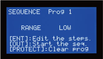
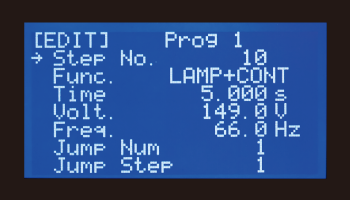
Sequence mode
Users can program frequently used waveforms and output sequences accordingly. The test patterns can be set by the operation on the front panel and by the remote control.
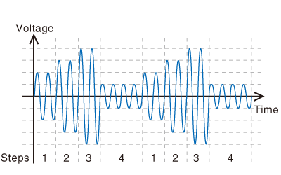
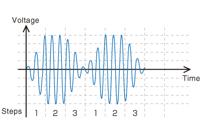
- Number of saved program: 3
- Max. step number: 32
- Step time: 1 ms to 999.999 s
- Number of jumps: 1 to 999 or limitless
- Operation: Constant, Ramp
- Settable parameters: AC voltage, Frequency, Step time, and Number of jumps.
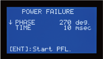
Momentary power interruption test mode
is possible to conduct a momentary power interruption test of the AC input devices.
It can reproduce the situations where the AC input line is unstable or momentary power interruption happens, thus the operating conditions of the AC input device (tested device) can be checked under such an environment.
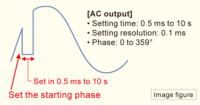
Setting time of momentary power interruption
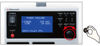
It is able to set time of instantaneous power failure with 0.1 ms unit in 0.5 ms to 10 s turning the rotary encoder.
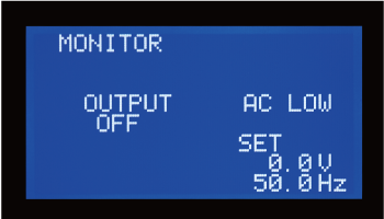
Comprehensive Measurement Functions
- Output voltage (RMS, Average, Peak)
- Output current (RMS, Average, Peak)
- Output power (Active, Apparent, Reactive)
- Power factor
- Crest factor
- Keeping peak current value
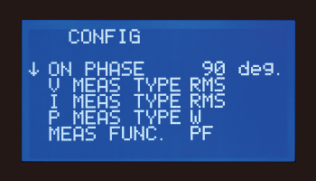
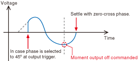
Selectable Phase at Output ON
This feature allows you to select the phase when the output is triggered on. Output off results in zero cross phase. (sec chart.)
Safety Functions
The DRS series is equipped with a safety function to protect the power supply and connected load. For example, if an abnormal current flows, such as a short circuit, the output is immediately stopped. However, if a load with an inrush current is connected, the output may be stopped by the overcurrent protection function. In this case, use a product with a margin for output current or use the SRK series with a current limit function. Some loads have inrush currents that flow more than 10 times the rated current.
Remote Control
Standard Function and Plenty of Options
As the external control and the USB interface are equipped as standard, they are applicable to the automation of the production line immediately.
And control by LAN, RS-232C, RS-485, and GPIB is possible by the optical interface/digital interface option.

Remote control
- Output ON/OFF
- Voltage control
- Frequency control
- Switching range
- Output of fault
- Interlock
- REMOTE/LOCAL
- Selection of control
Interface
- USB
- Options
-
- GPIB
- Optical interface/Digital interface:
LAN, USB, RS-232C, RS-485, GPIB
* In selecting the optional interface board, the USB interface as standard is not included.
Connector for Remote Control (REMOTE)
- Switching REMOTE/LOCAL
It is able to switch each or all modes of voltage, frequency, and range with a TTL signal. - External output ON/OFF
It is able to ON/OFF output with relay or TTL signal. - Output status
COMMON is floating with the open-collector output. - Output voltage control
- Output frequency control
- Output range control
* COMMON of REMOTE and the chassis are connected internally.
Specifications
- Input voltage
- 90 to 132/180 to 250 Vac, 50/60 Hz, Single-phase
- Output range (Hi/Lo)
-
[Local] Hi/Lo selectable RANGE switch on the front panel
[Analog remote] Short/Open or TTL (Low/High)
[Digital remote] Command - Output voltage control
-
[Local] VLT/FRQ selectable switch and rotary encoder on the front panel
[Analog remote] External control voltage 0 to 10 Vdc
[Digital remote] Command - Output frequency control
-
[Local] VLT/FRQ selectable switch and rotary encoder on the front panel
[Analog remote] External control voltage 0 to 10 Vdc
[Digital remote] Command
Options
- -LGb *
-
Built-in GPIB interface port (Scheduled for discontinuation in December 2028)
External output ON/OFF, Switching voltage range, Variable voltage, Variable frequency, Status, Monitor for voltage and current.
- -LGmb *
-
Digital interface port
Enables digital control via LAN/USB/RS-232C/RS-485/GPIB.- -LGmb: Digital interface port + modular cable 2 meters length
- -LGmb(Mc0.15): Digital port interface + modular cable 0.15 meters length
- -LGmb(Mc0.5): Digital port interface + modular cable 0.5 meters length
An adapter is required separately when using the Adapter. For details, click here.
- -LGob *
-
Optical interface port
With optical communication, isolation control is performed. As complete isolation is performed by means of optical fiber, this enables advanced prevention of erroneous operations involved with transient phenomena caused by surges, inductive lightning, external noise, etc.- -LGob: Optical interface port + optical cable 2 meters
- -LGob(Fc5): Optical interface port + optical cable 5 meters
- -LGob(Fc10): Optical interface port + optical cable 10 meters
- -LGob(Fc20): Optical interface port + optical cable 20 meters
- -LGob(Fc40): Optical interface port + optical cable 40 meters
An adapter is required separately when using the Adapter. For details, click here.
Select the optional optical interface port (-LGob) when using this DC power supply under the following conditions.
- Noisy environments such as factories (example: when motors or coils are used near loads or power sources).
- If this power supply and your controller (PC or PLC) cannot be installed within 2 meters.
- When there is a possibility of arcing or an output short-circuit.
- -LN
-
Output state auto-recovery (former: no power failure protection)
The output will automatically be ON with power restored without resetting.
- -LNh
-
No carry handle equipped
Select this option when installing in a rack-mount shelf.
- Selecting each individual option simultaneously in -LEt, -LGob, -LUs1, and -L(Mc0.5) or -L(Mc0.15)
- In selecting the optional interface port, the USB terminal as standard is not included.
How to Order
When ordering, add Option No. to Model How to Order No. in alphabetical order. Example: DRS500-LGbNNh, DRS1000-LGob(Fc10)NNh
Additional accessories
- Digital interface port
-
To use Matsusada Precision's digital interface, you need to prepare a digital interface adapter separately.
The following interface adapters are available according to your controller port.- CO-E32m: LAN Adapter
- CO-U32m: USB Adapter
- CO-MET2-9: RS-232C (9 pin) Adapter
- CO-MET2-25: RS-232C (25 pin) Adapter
- CO-MET4-25: RS-485 (25 pin) Adapter
(CO-MET2-9/CO-MET2-25/CO-MET4-25: The connector is D-sub type.) - CO-G32m: GPIB Adapter (Scheduled for discontinuation in December 2028)
Example of communication with a digital adapter 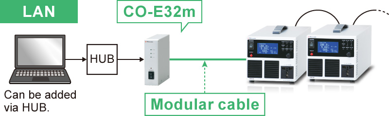
For details, refer to CO/USB series
- Optical isolation adapter
-
To use the optical interface, you need to prepare an optical interface adapter separately.
The following interface adapters are available according to your controller port.- CO-E32: LAN to optical interface adapter
- USB-OPT: USB to optical interface adapter
- CO-OPT2-9: RS-232C (9 pin) to optical interface adapter
- CO-OPT2-25: RS-232C (25 pin) to optical interface adapter
- CO-OPT4-25: RS-485 (25 pin) to optical interface adapter
- CO-G32: GPIB to optical interface adapter (Scheduled for discontinuation in December 2028)
Example of communication with optical fiber 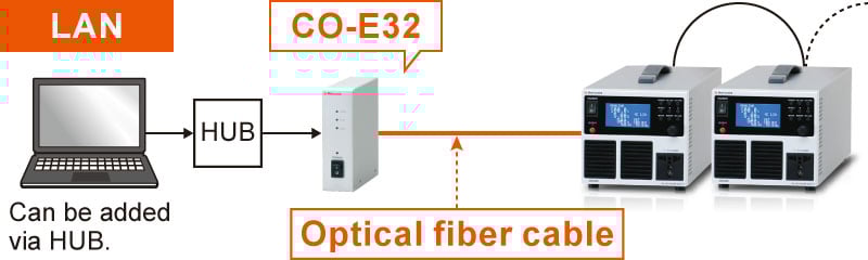
For details, refer to CO/USB series
- Application software
-
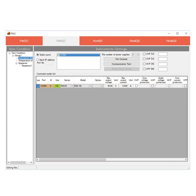
PSS2en series: Remote control, Test workflow design, and Data logging
Click here for the PSS2en seriesPSS2en is the dedicated software that can actuate various power supplies, electronic loads, and digital controllers for power supplies manufactured by Matsusada Precision Inc. with a simple setup.
It is perfect for the aging test, the burn-in test, and the withstand voltage test for electronic parts, as well as for the endurance test, intermittent/continuous operation test, or various simulation tests for automobile electric components.

- AC Input Cable
-
DRS500 Standard CABLE TYPE1 

125 V/10 A 2.5 meters
Fixed lengthSold separately CABLE TYPE3 
250 V/10 A 2.5 meters
Fixed lengthSold separately CABLE TYPE4 
250 V/10 A 2.5 meters
Fixed length -
DRS1000 Standard CABLE TYPE8 125 V/15 A 2.5 meters
Fixed lengthSold separately CABLE TYPE3 250 V/10 A 2.5 meters
Fixed lengthSold separately CABLE TYPE4 250 V/10 A 2.5 meters
Fixed length -
DRS2000 Sold separately CABLE TYPE5 

250 V/25 A 2.5 meters Sold separately CABLE TYPE11 250 V/30 A 2.5 meters
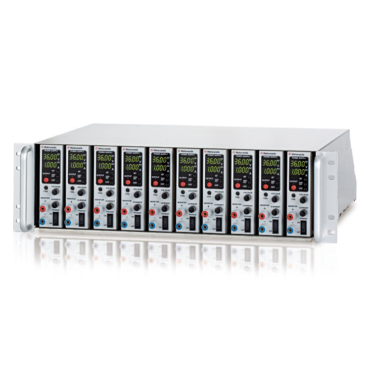
- Rackmount shelf
-
RMO-133H-DRJ
This rackmount shelf can accommodate up to three DRS500 units or two DRS1000 units. It can be installed in a 19-inch rack.
For details, please refer to the rackmount shelf page.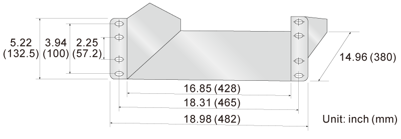
Dimensions
Download
If you are unable to download a file
Please try the following solution.
- Please press Ctrl+F5 to clear the cache of your web browser and try again.
- Please restart your web browser and log in again to try again.
- Please change your web browser to another browser and try again.
- Restart the computer and try again.
- Please try again on a different computer.
-
DRS series Datasheet
Date: 2025-10-21 rev 21
PDF (2,577 KB)
-
Programmable AC Power Source Selection Guide
Date: 2026-03-26 rev 08
PDF (3,012 KB)

-
DRS series Basic Instruction Manual
Date: 2025-06-23 rev 1.0
PDF (617 KB)
-
DRS series Instruction Manual
Date: 2025-06-23 rev 2.0
PDF (3,379 KB)
-
DRS series Instruction Manual (LGb, LGob option)
Date: 2025-06-23 rev 2.0
PDF (1,189 KB)
-
DRS series USB Communication Manual
Date: 2025-06-23 rev 2.0
PDF (626 KB)
-
USB driver for Windows 10, 11
Date: 2025-12-19 rev 2.12.36.20
ZIP(1,629KB)
-
USB driver for Windows XP, 7, 8, 8.1
Date: 2025-01-22 rev 1.7.6
ZIP (6,504 KB)
Login Required
-
DRS series Datasheet
Date: 2025-10-21 rev 21
PDF (2,577 KB)
-
Programmable AC Power Source Selection Guide
Date: 2026-03-26 rev 08
PDF (3,012 KB)
-
DRS series Basic Instruction Manual
Date: 2025-06-23 rev 1.0
PDF (617 KB)
-
DRS series Instruction Manual
Date: 2025-06-23 rev 2.0
PDF (3,379 KB)
-
DRS series Instruction Manual (LGb, LGob option)
Date: 2025-06-23 rev 2.0
PDF (1,189 KB)
-
DRS series USB Communication Manual
Date: 2025-06-23 rev 2.0
PDF (626 KB)
-
USB driver for Windows 10, 11
Date: 2025-12-19 rev 2.12.36.20
ZIP(1,629KB)
-
USB driver for Windows XP, 7, 8, 8.1
Date: 2025-01-22 rev 1.7.6
ZIP (6,504 KB)
On this website, we provide only the latest versions of information and instruction manuals for our products. Therefore, the newest versions of manuals on the website may differ from those that came with products you purchased in the past.