Overview of Inverter Technology
Power Inverter circuit and power inverter device
The term "inverter" essentially refers to a circuit that converts the current from DC to AC (power inverter circuit), but it can also refer to a power inverter device used in home appliances, such as air conditioners and washing machines.
Home appliances are not the only examples that benefit from inverter devices. Elevators and conveyors do not accelerate or stop suddenly because the acceleration of the motor is well-regulated by power inverter devices that help in adjusting the motor speed.
What type of technology is a power inverter device?
Consider an air conditioner as an example. A conventional non-inverter model controls temperature by repeatedly turning the compressor motor on and off. This results in unstable indoor temperatures and high power consumption due to the frequent start-stop cycles.
In contrast, an inverter-equipped air conditioner controls the motor speed continuously. It runs at high speed to cool the room quickly, then slows down to maintain the set temperature. This variable speed control eliminates energy waste and ensures stable operation compared to simple on/off control.
Hence, the word "inverter" is often used in the field of home appliances. In recent years, inverters have also played an active role in the increasing number of induction cookers that use AC currents with extremely high frequencies ranging from 20 kHz to 90 kHz for their operations; this is only possible by changing the frequency with a power inverter device.
The ability to flexibly change the rotation speed and acceleration of the motor to suit the required application is highly useful. How does a inverter device allow us to flexibly change the rotation speed of a motor?
Frequency and Rotation Speed
Power inverter devices are often used to change the AC current from an electrical outlet to a desired frequency or voltage.
The voltage and frequency supplied from the electrical outlet are determined as 100V, 50Hz for eastern Japan, and 100V, 60Hz for western Japan, and the rotation speed of the motor is determined by the frequency.
Power inverter device configuration
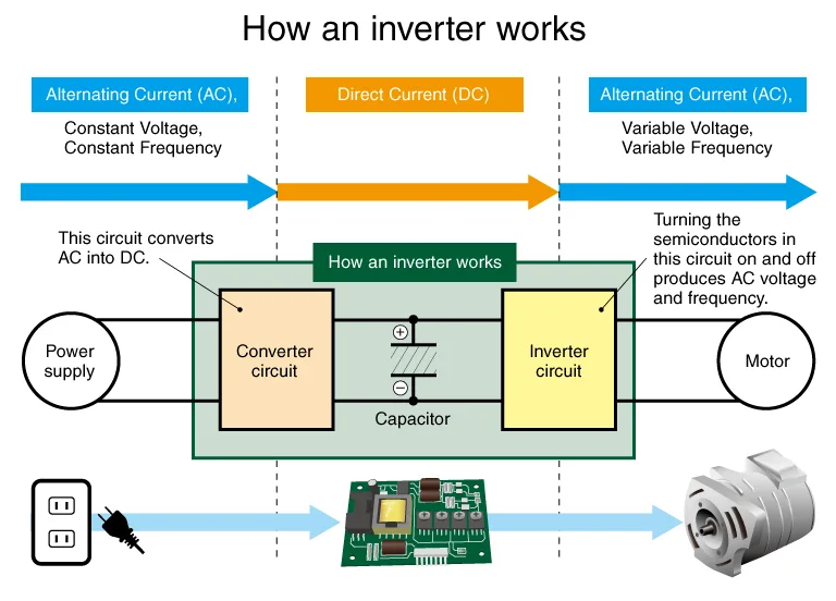
How does an inverter change the frequency? An inverter consists of three elements: a converter circuit that converts AC current into DC current, a capacitor, and a power inverter circuit.
First, the converter circuit converts the AC to DC and then repeatedly charges and discharges the capacitor to create a stable DC. Next, the inverter circuit converts the DC to AC at a desired frequency and voltage for output.
Principles of power inverter circuits
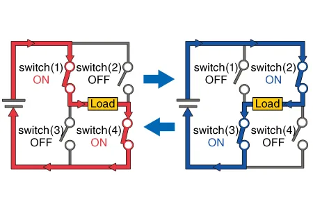
In this section, we explain the principle of power inverter circuit operation based on the circuit diagram with four switches as shown in the figure below. An inverter circuit converts direct current into alternating current.
When a DC power supply is connected to the circuit and switches (1) and (4) are turned on, switches (2) and (3) are turned off. When switches (1) and (4) are turned off, switches (2) and (3) are turned on, repeating in pairs in a fixed cycle, the direction of the current flowing to the load is switched and output alternates in positive and negative voltages, creating an AC current. This is referred to as switching technology.
A circuit using switching technology can also convert AC into DC. If switches (1) and (4) are closed when the voltage is in the positive direction, and switches (2) and (3) are closed when the voltage is in the negative direction, the current would always flow in the same direction as the load.
Power inverter Circuits and Smart Grids
With the development of IT and the widespread use of IoT, the concept of a "smart grid" has been proposed to supply and consume electricity more efficiently. The smart grid is a concept that uses IT to understand real-time power consumption and concentrate power transmission in accordance with it.
In order to make smart grids possible, the latest technologies such as electric vehicles and solar cells are needed. Inverter circuits are expected to make further contributions in this regard as well.
Electric cars run on electricity from the batteries installed in the car to drive the motor. However, as the electricity obtained from the battery is DC, it needs to be converted to AC in order to run the motor efficiently. This is where the inverters come into play.
The same applies to utility-scale solar power plants. Since the electricity generated by solar panels is DC, it must be converted to AC with the same frequency and voltage as the grid for transmission.

Principle of switching power supply
The principle of inverters, which can output power at will by operating and controlling switches at high speed, is also used to make converters more energy efficient and compact. Converters that use switches to convert power are called "switching power supplies".
Electronic devices require a stabilized direct current with little voltage fluctuation. In the past, a type of "AC adapter" called a linear power supply was used to convert household AC power to DC at a lower voltage. The adapters for game consoles and laptops are probably the most obvious examples.
Linear Power Supply: A traditional linear power supply uses a large transformer to step down the AC voltage directly from the input. The low-voltage AC is then rectified into DC and smoothed by capacitors. Because of the large, heavy iron-core transformer required for low frequencies (50/60 Hz), these adapters were bulky.
Switching Power Supply: Switching power supplies (SMPS) operate differently. The input AC is first rectified directly into high-voltage DC. This DC voltage is then switched on and off at high speed by semiconductor devices, creating a high-frequency pulsed voltage.
This high-frequency signal passes through a much smaller, lighter transformer to step down the voltage. Finally, it is rectified and smoothed again to provide a stable DC output. The high operating frequency (tens to hundreds of kHz) allows for significant miniaturization of the transformer and components.
The latest technology in power inverters
The latest trend in inverters focuses on power devices. Power devices are a category of circuit elements made of semiconductors and can supply power as semiconductors in inverters and converters. Power devices capable of switching include power transistors and thyristors.
Power devices, such as transistors and thyristors, are key components in inverter circuits. While they offer high current capacity and voltage tolerance, they inevitably experience power loss in the form of heat during operation (conduction and switching losses).
Although silicon (Si) has traditionally been the dominant material, its performance is approaching its theoretical limits, making further significant reductions in power loss difficult.
Consequently, the industry is shifting toward next-generation materials like Silicon Carbide (SiC) and Gallium Nitride (GaN). These wide-bandgap semiconductors offer superior conductivity and thermal characteristics compared to silicon, enabling higher efficiency and more compact designs.
Related Technical Articles
- Application: Inverter (Power inverter)
- Types of Power Semiconductors -Reliability and Performance Tests
- How to Use Bidirectional Power Supply
- Power Electronics for a Decarbonized Society
- What is Grid Interconnection? The Fundamentals Explained
- AC Power Supply: Fundamentals and International Differences
Recommended products
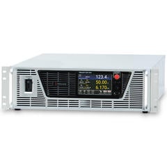
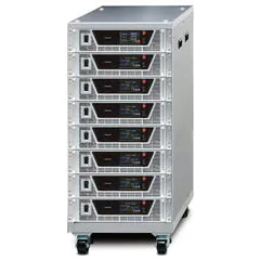
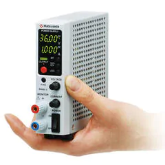
Matsusada Precision manufactures a variety of power supplies used in the development and manufacture of inverters. Bidirectional power supplies are ideal for regenerating inverter power and effectively utilizing energy.