Multimeter Components and Functions
A multimeter, also known as an electrical tester, circuit meter, or circuit multimeter, is a single-unit measuring instrument that can measure multiple electrical values such as voltage, resistance, and current during experiments and evaluations. They also aid in the maintenance and inspection of electrical equipment.
Although there are some differences depending on the industry or type of business, those with an analog meter display are usually called "testers" or "analog multimeters," while those with a digital meter display are called "multimeters".
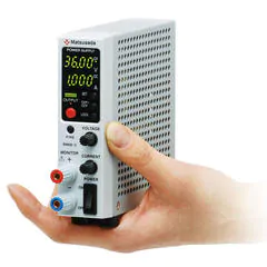
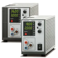
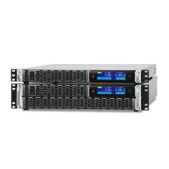
Large, stationary units are often called "benchtop multimeters." The term Digital Multimeter (DMM) is a general term for any multimeter with a digital display, regardless of its size.
Although they are referred to in several ways, their basic functions remain the same.
Multimeter Description:
- (1) Test Leads (Probes)
Input devices used to connect the multimeter to the circuit or device under test. Ideally, use probes with safety ratings appropriate for the voltage being measured. - (2) Input Terminals
Ports where test leads are connected. The correct terminal must be selected based on the measurement type (Voltage/Resistance vs. Current). - (3) Function Switch (Rotary Dial)
Used to select the measurement mode (AC/DC voltage, current, resistance) and the appropriate range. - (4) Function button (select button)
This is used to activate ancillary functions. In a digital multimeter, the function switch and function button are combined to switch the measurement mode. For example, press the function button to switch on the LCD display. - (5) Zero ohms adjuster knob
This knob is used to correct the display deviations caused by internal resistance, etc. - (6) Meter Scale
- (7) Meter pointer
- (8) Display board

Various measurement methods using the multimeter
Let us review the various measurement methods.
First, in an analog multimeter, adjust the zero position of the multimeter as a preliminary preparation before taking measurements, and also check the continuity. Set the range switch to the resistance measurement mode, and place the test lead pins against each other; if the value is close to 0 Ω, it is OK.
Measurements with a multimeter are essentially as follows:
(1) Insert the red plug of the test lead into the + input terminal and the black plug into the - input terminal.
(2) Adjust the measurement range.
(3) Make the test pin contact the measurement area.
(4) Check the scale that matches the measuring range of the switching knob from the meter scale, and read the numerical value shown by the ammeter's pointer (in the case of a digital multimeter, read the numerical value from the display panel).
Thus, the measurements are performed in four steps. Excessive current or voltage may cause a malfunction. Therefore, if the measurement value is unpredictable, start the measurement from the maximum range in any mode and then lower the range while observing the situation.
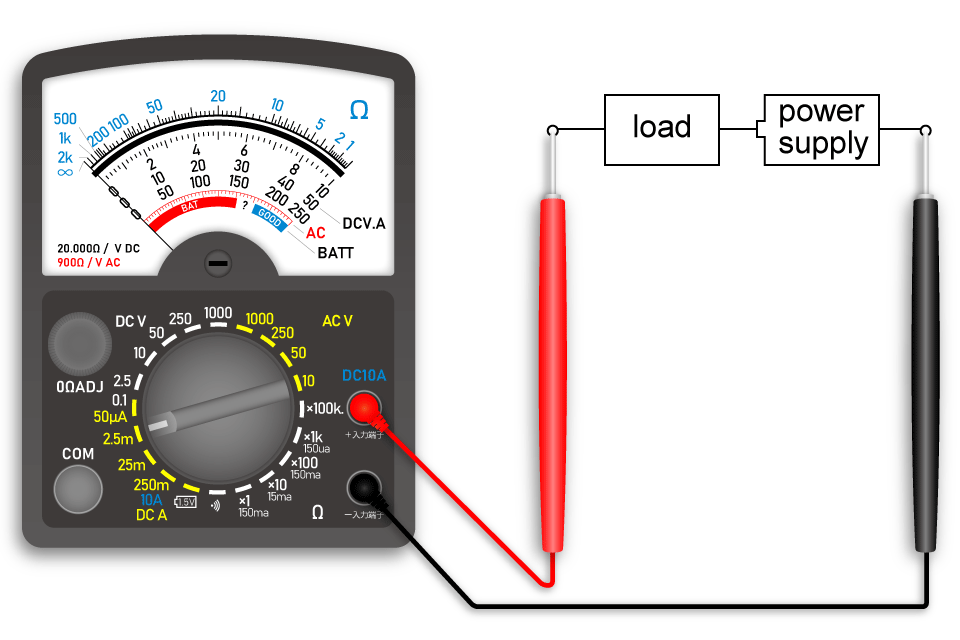
How to measure AC/DC voltage
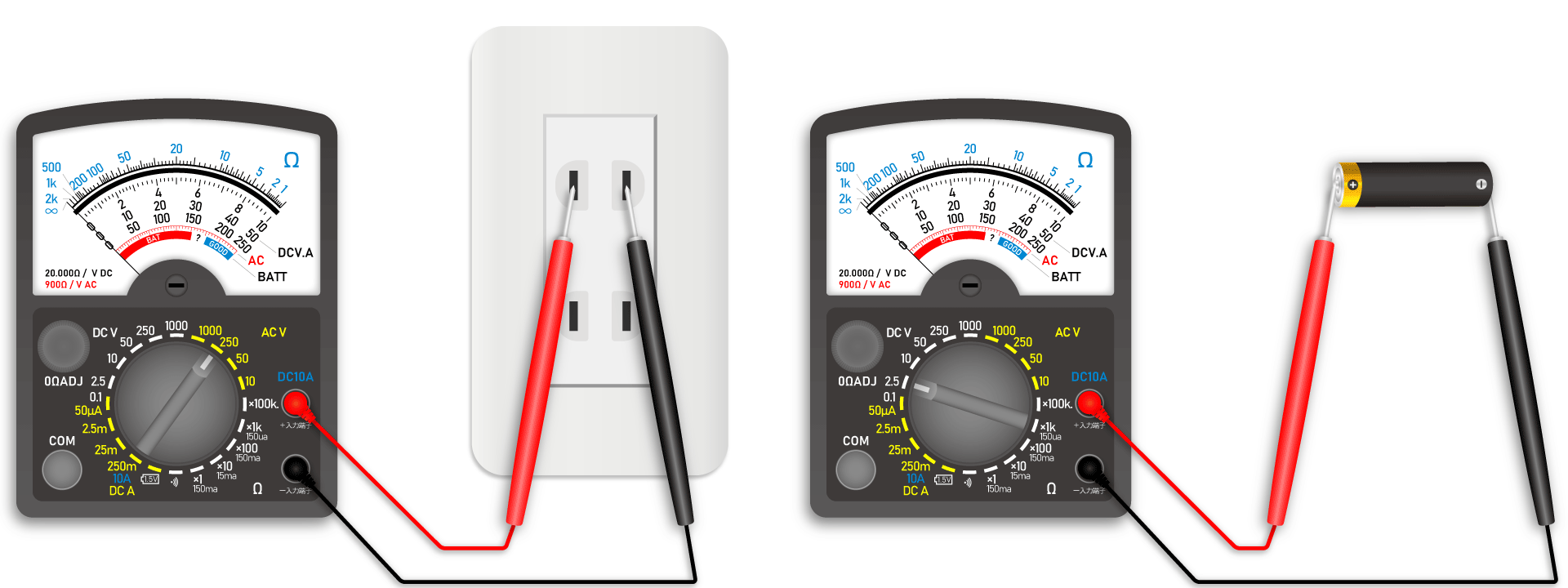
After inserting the test lead into the terminals, switch the range knob to AC/DC voltage mode to select the expected voltage range. For DC voltage, connect the black probe to the negative (-) side and the red probe to the positive (+) side. For AC voltage, the polarity of the probes does not matter.
How to measure resistance
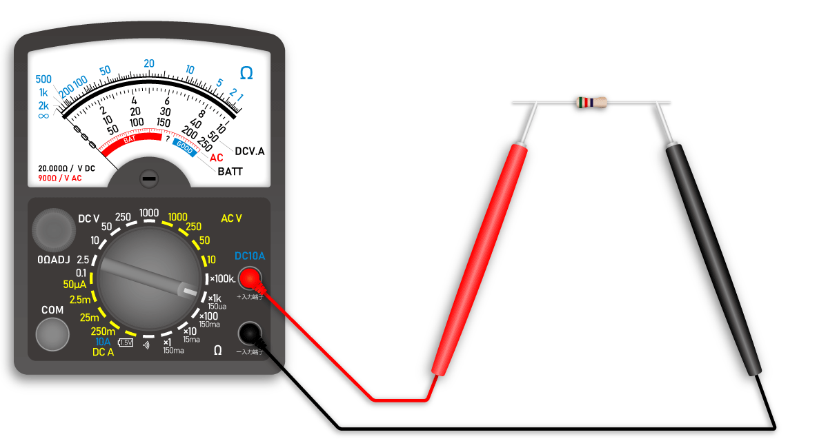
After inserting the test lead into the terminals and switching the range switch knob to resistance mode, apply the test probes to each other and turn the zero-ohm switch knob to set the pointer to the 0 Ω position.
After alignment, place the red and black test probes on both ends of the measurement target. Be sure to turn off the power to the measurement object before taking the measurement.
How to measure DC current
To measure current, the multimeter must be connected in series with the circuit. First, turn off the power to the circuit. Insert the test leads into the correct current-measuring terminals and switch the range dial to DC current mode. Break the circuit at the measurement point and connect the red probe to the higher potential side and the black probe to the lower potential side. Once connected securely, turn the power back on to read the value. Note that many analog multimeters cannot measure AC current.
Differences between digital and analog multimeters
There are two types of multimeters: analog and digital., Although digital multimeters have been more prevalent as the world is becoming digitalized, both have their own merits and demerits.
Advantages of digital multimeters
- Readings are displayed numerically, eliminating reading errors and parallax issues.
- Digital models typically offer higher precision and resolution.
- Advanced functions are often available, such as thermocouple temperature measurement, frequency measurement, and continuity checks.
- Generally easier to operate than analog multimeters.
- A wide variety of models are available, ranging from basic handheld units to high-precision benchtop models. High-end models offer superior safety, durability, and accuracy. Additional features may include multi-channel measurement, wide voltage/current ranges, and PC connectivity via USB.
Disadvantages of digital multimeters
- There are numerous functions; it takes time to familiarize.
- Reading fluctuating values is difficult.
- Operation requires batteries
Advantages of analog multimeters
- The continuous movement of the needle provides an intuitive visualization of changing or fluctuating values.
- It is easier to observe trends in voltage and current, as the needle's deflection clearly indicates variations that might be hard to read on a digital display.
- They can measure voltage and current without needing batteries.
Disadvantages of analog multimeters
- Their lower input impedance can affect the circuit under test, leading to measurement errors.
- Reading the correct scale requires care and can be prone to parallax error.