This article explains how to read the values of resistors and capacitors, fundamental components in electronics.
Matsusada Precision offers a wide variety of power supply units, such as DC power supplies (programmable DC power supplies), high-voltage power supplies, and AC power supplies. Please inquire if you have any questions.
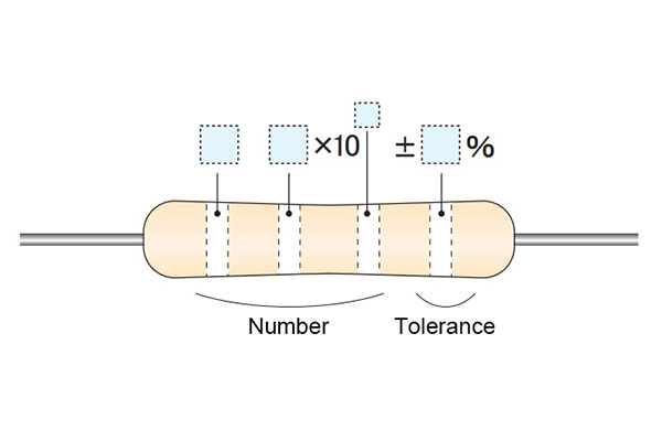
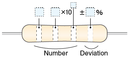
Resistor Color Codes
Reading Resistor Color Codes
| Color | Black | Brown | Red | Orange | Yellow | Green | Blue | Purple | Gray | White | Silver | Gold |
|---|---|---|---|---|---|---|---|---|---|---|---|---|
| Number | 0 | 1 | 2 | 3 | 4 | 5 | 6 | 7 | 8 | 9 | - | - |
| Numerical value | 100 | 101 | 102 | 103 | 104 | 105 | 106 | - | - | - | 10-2 | 10-1 |
| Tolerance | ±20% | ±1% | ±2% | - | - | - | - | ±10% | ±5% |
Carbon film resistor (4-band code)
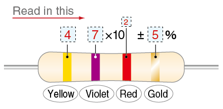
47 x 102 = 4700 Ω (4.7 kΩ), ±5%
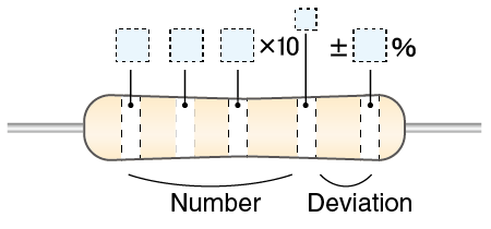
Metal film resistor (with five bands)
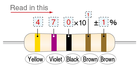
4700 Ω = 4.7 kΩ
Surface Mount (Chip) Component Markings
Chip resistors
Chip resistors use alphanumeric codes on their surface to indicate their resistance value. The following is an example of the transformation rules. (It also has other particular markings or rules.)

- [Example]
-
- 103 = 10 x 103 = 10000 Ω (10 kΩ)
- 1003 = 100 x 103 = 100000 Ω (100 kΩ)
- R047 = Replacing the R with decimal point = 0.047 Ω (47 mΩ)
- 10L0 = Replacing the L with decimal point of mΩ = 10 mΩ
Chip capacitor

- Code "471": 47 x 101 = 470 pF
Chip inductor (coil)
- Code "471": 47 x 101 = 470 µH
Capacitor/Standard Resistance Value
The E series is a system of standardized "preferred values" for electronic components. These values are chosen so that the tolerance range of one component value nearly touches the tolerance range of the next, ensuring efficient coverage of the entire range.
| E3 | E6 | E12 | E24 |
|---|---|---|---|
| +/- 40% tolerances | +/- 20% tolerances | +/- 40% tolerances | +/- 20% tolerances |
| 1 | 1 | 1 | 1 |
| 1 | 1 | 1 | 1.1 |
| 1 | 1 | 1.2 | 1.2 |
| 1 | 1 | 1.2 | 1.3 |
| 1 | 1.5 | 1.5 | 1.5 |
| 1 | 1.5 | 1.5 | 1.6 |
| 1 | 1.5 | 1.8 | 1.8 |
| 1 | 1.5 | 1.8 | 2 |
| 2.2 | 2.2 | 2.2 | 2.2 |
| 2.2 | 2.2 | 2.2 | 2.4 |
| 2.2 | 2.2 | 2.7 | 2.7 |
| 2.2 | 2.2 | 2.7 | 3 |
| 2.2 | 3.3 | 3.3 | 3.3 |
| 2.2 | 3.3 | 3.3 | 3.6 |
| 2.2 | 3.3 | 3.9 | 3.9 |
| 2.2 | 3.3 | 3.9 | 4.3 |
| 4.7 | 4.7 | 4.7 | 4.7 |
| 4.7 | 4.7 | 4.7 | 5.1 |
| 4.7 | 4.7 | 5.6 | 5.6 |
| 4.7 | 4.7 | 5.6 | 6.2 |
| 4.7 | 6.8 | 6.8 | 6.8 |
| 4.7 | 6.8 | 6.8 | 7.5 |
| 4.7 | 6.8 | 8.2 | 8.2 |
| 4.7 | 6.8 | 8.2 | 9.1 |
| E96 | ||||
|---|---|---|---|---|
| +/- 1% tolerances | ||||
|
|
||||
| 1.00 | 1.62 | 2.61 | 4.22 | 6.81 |
| 1.02 | 1.65 | 2.67 | 4.32 | 6.98 |
| 1.05 | 1.69 | 2.74 | 4.42 | 7.15 |
| 1.07 | 1.74 | 2.80 | 4.53 | 7.32 |
| 1.10 | 1.78 | 2.87 | 4.64 | 7.50 |
| 1.13 | 1.82 | 2.94 | 4.75 | 7.68 |
| 1.15 | 1.87 | 3.01 | 4.87 | 7.87 |
| 1.18 | 1.91 | 3.09 | 4.99 | 8.06 |
| 1.21 | 1.96 | 3.16 | 5.11 | 8.25 |
| 1.24 | 2.00 | 3.24 | 5.23 | 8.45 |
| 1.27 | 2.05 | 3.32 | 5.36 | 8.66 |
| 1.30 | 2.10 | 3.40 | 5.49 | 8.87 |
| 1.33 | 2.15 | 3.48 | 5.62 | 9.09 |
| 1.37 | 2.21 | 3.57 | 5.76 | 9.31 |
| 1.40 | 2.26 | 3.65 | 5.90 | 9.53 |
| 1.43 | 2.32 | 3.74 | 6.04 | 9.76 |
| 1.47 | 2.37 | 3.8 | 6.19 | - |
| 1.50 | 2.43 | 3.92 | 6.34 | - |
| 1.54 | 2.49 | 4.02 | 6.49 | - |
| 1.58 | 2.55 | 4.12 | 6.65 | - |
- These standard values follow a geometric progression based on the 10th root system.
- Common ratio calculation for E(n) series:
Ratio = (where n = 3, 6, 12, 24, etc.)
Capacitor Marking
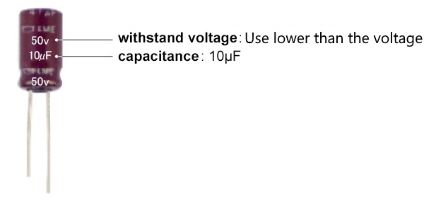
Aluminum electrolytic capacitor
Ceramic and film capacitors
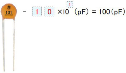
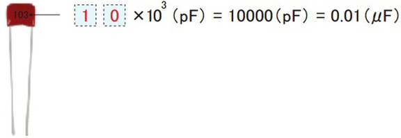
For many ceramic and film capacitors, the capacitance is marked using a three-digit code. The value is read in picofarads (pF).
Ceramic capacitor
Film capacitor
Reference
- 1 pF = 1 x 10-12 F
- 1 μF = 1 x 10⁻⁶ F
Decoding 3-Digit Component Codes
| Marking | Capacitor | Resistance |
|---|---|---|
| 106 | 10 μF | 10 MΩ |
| 105 | 1 μF | 1 MΩ |
| 104 | 0.1 μF | 100 kΩ |
| 103 | 0.01 μF | 10 kΩ |
| 102 | 1000 pF | 1 kΩ |
| 101 | 100 pF | 100 Ω |
| 100 | 10 pF | 10 Ω |
E series: The resistance does not always include all arbitrary values, and it is defined based on E series.
Rated voltage: Capacitors have the rated voltage, and in some cases, they are directly shown by 50 V or 100 V, and also marked by alphabetic character codes. For instance, 0E is 2.5 V.
| A | B | C | D | E | F | G | H | J | K | P | V | W | |
|---|---|---|---|---|---|---|---|---|---|---|---|---|---|
| 0 | 1 | 1.25 | 1.6 | 2 | 2.5 | 3.15 | 4 | 5 | 6.3 | 8 | 1.8 | 3.5 | 4.5 |
| 1 | 10 | 12.5 | 16 | 20 | 25 | 31.5 | 40 | 50 | 63 | 80 | 18 | 35 | 45 |
| 2 | 100 | 125 | 160 | 200 | 250 | 315 | 400 | 500 | 630 | 800 | 180 | 350 | 450 |
| 3 | 1000 | 1250 | 1600 | 2000 | 2500 | 3150 | 4000 | 5000 | 6300 | 8000 | 1800 | 3500 | 4500 |
Polarity Marking


Click here for more information about Matsusada Precision products.
Related Technical Articles
Recommended products
Matsusada Precision's DC power supplies and other power supply equipment provide the best solutions for electric circuit testing applications.