What is an inductor (coil)?
Inductors, also known as coils, are passive electronic components labeled as "L" in circuit diagrams, similar to how resistors constitute "R" and capacitors "C." Their primary function is to store energy in a magnetic field when electric current flows through them. This property allows inductors to oppose changes in current, helping to stabilize electrical flow. The capability of an inductor is measured in inductance, with the unit being the Henry (H).
Structurally, an inductor consists of a conductor wound into a coil. While some are air-core (wound only with conductors), others contain a magnetic core inside the winding to enhance inductance. The inductance value is generally proportional to the square of the number of turns and the cross-sectional area, and inversely proportional to the length of the coil.
Basic principles of inductors
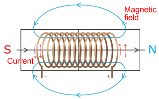
First, let's briefly look at the operating principle of inductors. When an electric current flows through a conductor, a magnetic field is generated around it according to the Right-Hand Rule. If the conductor is wound into a coil, the magnetic fields generated by each turn combine (link) to form a strong magnetic field, effectively acting as an electromagnet (Figure 1). Conversely, it is also possible to generate an electric current from a changing magnetic field.
Principle of inductors
When a magnet is moved closer to or further away from an inductor, the magnetic field around the inductor changes. This change induces an electric current in the inductor, which generates a magnetic field that opposes the original change, in an attempt to maintain the direction and strength of the magnetic field. This phenomenon is called electromagnetic induction.
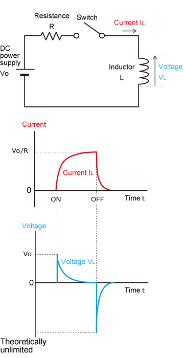
As shown in the circuit diagram, when a DC current flows through an inductor (Figure 2), an electromotive force in the direction that interferes with the current is generated at the beginning of the current flow. This property is called the self-inductive effect. However, later on, as the DC current reaches a certain value, the magnetic flux ceases to change, and the electromotive force is no longer generated. Thus, the current is no longer obstructed.
The electromotive force generated in an inductor is proportional to the rate of change of the current (ΔI/Δt) .
V: Electromotive force (V)
L: Inductance (H)
ΔI /Δt: Rate of change of current (A/s)
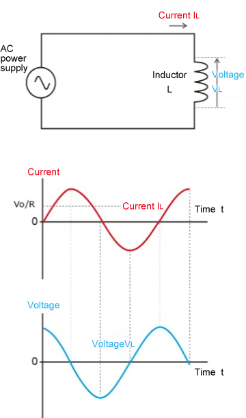
On the other hand, when AC current is applied (Fig. 3), the voltage becomes larger when the current rises from 0 because the rate of change of current is the largest. As the rate of current increase slows down, the voltage decreases, and at the point where the current reaches its maximum, the voltage becomes zero.
As the current begins to fall from its maximum value, a negative voltage starts to be generated, and the voltage is at its lowest point when the current reaches zero. Examining the waveforms of the voltage and current, we can see that the electromotive force is generated with a quarter-cycle phase lag (or a 90-degree phase lag).
Therefore, AC current is more difficult to pass than DC current. Furthermore, if the frequency of AC exceeds a certain value, the current will be constantly blocked by the electromotive force, and the current will not flow. Therefore, the higher the frequency of the AC voltage, the more difficult it is for the current to flow.
To summarize
- When current flows, the magnetic force is generated.
- When the magnetic field changes, current flows
- It is easy to pass direct current and difficult to pass alternating current.
Because of these properties, inductors are used in a variety of applications.
Roles of inductors (coils)
1. Applications for power supply circuits
Inductors pass Direct Current (DC) easily but oppose Alternating Current (AC). They act as filters that suppress AC ripples, resulting in a smoother DC output. For this reason, inductors are essential in power supply circuits used to drive DC electronic devices.
Since standard power distribution is AC, it must be converted and smoothed for DC circuits. Inductors are used in these smoothing circuits to stabilize the output. Additionally, because they block high-frequency AC, inductors are effective at removing noise. In power supply applications, these components are typically referred to as power inductors or choke coils.
2. Applications for high-frequency circuits
High-frequency circuits, such as those used in wireless LANs (Wi-Fi) and communications, operate in the MHz to GHz range. Standard power inductors are unsuitable for these frequencies; instead, inductors with a high Q-factor (Quality Factor) are required.
Ideally, an inductor would act purely as an inductance. However, real-world components have internal resistance and parasitic capacitance (stray capacitance) between the windings. This parasitic capacitance causes the inductor to behave like a capacitor at certain frequencies.
Capacitors, unlike inductors, have the property of allowing alternating current (AC) to pass while blocking direct current (DC). While an inductor typically exhibits inductive characteristics at lower frequencies, it possesses a self-resonant frequency. When the frequency exceeds this certain level, the component's capacitive characteristics begin to dominate over its inductive characteristics, rendering it unsuitable for use as an inductor.
At the "self-resonant frequency," the inductive and capacitive reactances cancel each other out. Beyond this frequency, the component functions more like a capacitor than an inductor, preventing current flow as intended. High-frequency circuits utilize these resonance characteristics to filter or select specific frequency signals.
3. Applications for power transformer
Inductors are also used in transformers installed on utility poles and the like. In transformer applications, they are not called inductors but coils more often. When an AC voltage is applied to an inductor, the current flowing through it changes, which causes the magnetic force to change, and this magnetic force affects the surrounding inductors, generating a voltage. This kind of action is called "mutual induction.
In a transformer, a changing magnetic field, generated by current flowing through a coil with a smaller number of turns, induces a higher voltage in a nearby coil with a larger number of turns, thereby raising the voltage.
In addition to converting voltage for power circuits, there are other types of inductors used in radio and wireless circuits, such as "IFTs" that extract intermediate frequency signals and "audio transformers" that convert audio frequency signals.
Types of inductors (coils)
Next, let's look at the main inductor classifications and their characteristics. There are many ways to classify them, but here we will first classify them according to the structure of the winding.
1. Wire-wound inductor
A wire-wound inductor is an inductor that is closest in shape to a coil, with the conductor wound in a spiral shape, as explained in the first section. Some inductors are hollow, while others have conductors wrapped around a core (like a bobbin used in sewing machines). There are a variety of sizes and shapes depending on the application and inductance value.
They are suitable for circuits where a large current must flow or where a high inductance value is required.
2.Multilayer inductors
Multilayer inductors are made of alternating layers of ferrite or ceramic and coil patterns. The coil patterns are created not by winding conductors, but by screen-printing them on top of ferrite or other materials. Multiple layers of these patterns are then stacked to achieve the desired inductive properties. On the other hand, due to its inherent structure, it also incorporates an internal capacitive component.
Inductors have different names depending on their use
Inductors are used in a variety of places in our daily lives. Depending on the application, they are called coils, chokes, reactors, solenoids, line filters, etc., as in the case of transformers. The following is a list of typical names.
- Choke coil
-
An inductor used primarily in power supply circuits is often called a choke coil. It gets its name from its ability to "choke" off (block) high-frequency AC noise while allowing DC current to pass through. It is essential for smoothing outputs and filtering noise.
- Common mode filter
-
A common mode filter is characterized by the shape of two choke coils integrated together and is used to remove noise in digital interfaces such as USB and HDMI.
- Toroidal coil
-
A coil with a donut-shaped ferromagnetic core is called a toroidal coil. Unlike coils with rod-shaped cores, the magnetic flux in the winding leaks less to the outside. Therefore, it is highly stable and reproducible and often used in high-frequency circuits.
Related Technical Articles
Recommended products
Matsusada Precision manufactures bipolar power supplies and high-voltage amplifiers that are ideal for evaluating inductive loads such as coils, inductors, and motors.