


History of Power Electronics
Power electronics refers to the technology of converting and controlling electric power using semiconductor power devices. It plays a critical role in achieving a decarbonized society by enabling the efficient use of electricity. To achieve this, improving energy utilization is essential, with a particular focus on enhancing control efficiency.
The term "power electronics" first appeared in 1973. The paper entitled "Power Electronics-Emerging from Limbo" was presented by William E. Newell at the Institute of Electrical and Electronics Engineers (IEEE). Until then, there were technologies related to electric power generation and control, such as motors and thyristors. However, it can be said that this was the time when the concept of integrated handling of electric power, electronics, and control was born. Power engineers didn't know about electronics, and electronics engineers didn't know about power control. Newell suggested that it was important to fill that gap.
After the concept of power electronics was born, the control efficiency of electric power came to be noticed, and it is now a keyword to support a decarbonized society.
Power Devices -Motor Type and Control-
While strictly a load device, motors are a primary focus in power electronics. ... Furthermore, most electricity (including thermal, nuclear, wind, and hydroelectric power) is produced by generators, which share a similar structural basis with motors. Advancements in motor technology directly correlate to advancements in power electronics and contribute significantly to energy savings.
Motors can be broadly divided into direct current (DC) motors and alternating current (AC) motors. Furthermore, it can be classified into several types, such as PM motors, brushless motors, servo motors, and stepping motors according to the structure and control method.
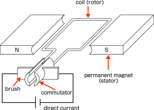
The basic structure of the motor is that the rotor rotates between the stators. At this time, the part that supplies power is called the brush. However, the presence of this brush causes friction between the brush and the commutator, resulting in inefficiency. In addition, the brush will wear, so it will be necessary to replace the brush regularly.
Therefore, a brushless motor that eliminates the brush has appeared. In particular, brushless motors that use three-phase alternating current are also used as motors for EVs.
- U = U-phase winding
- V = V-phase winding
- W = W-phase winding
- rotor = magnet
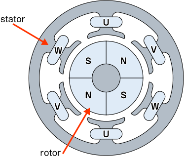
Fig: Structure of Brushless Motor
A permanent magnet is used for the rotor. Motors that use permanent magnets are called "PM motors." As shown in the figure, the one that uses a permanent magnet on the surface of the rotor is called "Surface Permanent Magnet Synchronous Motor (SPM)", and the one that is embedded inside is called "Interior Permanent Magnet Synchronous Motor (IPM)".
Some of these brushless motors use a ferromagnetic iron core instead of a permanent magnet for the rotor. This is called a "Reluctance Motor". Although the structure is simple because it does not use permanent magnets, it has been avoided because of noise, vibration, and large torque fluctuations. However, with the advancement of control using power electronics and computers, the range of use is expanding.
- U = U-phase winding
- V = V-phase winding
- W = W-phase winding
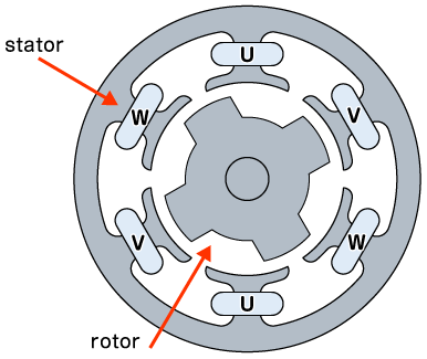
Fig: Structure of Reluctance Motor
Until now, servomotors have been the mainstream for controlling the rotation speed of rotors. By incorporating a servo mechanism, it has the advantage of automatically controlling the position and speed and is resistant to sudden load fluctuations, but it also has the disadvantage of being driven by a high voltage source.
In comparison, stepper motors operate in synchronization with pulse signals, so they have the advantage of being able to operate at low voltages and being miniaturized. On the other hand, the smoothness of rotation is inferior to that of servo motors. The reluctance motor mentioned earlier is also a kind of stepping motor, so these drawbacks are now being eliminated.
Power Devices -Direct Current and Alternating Current Conversion-
As a second example of a power device, let's introduce the current conversion. As you know, there are direct current (DC) and alternating current (AC) in electric current. Most electronic devices operate on DC, but most of the power transmission is done on AC. Therefore, it is very important to convert DC and AC to each other. And since a lot of electric power is always converted before being used in electronic devices, if the conversion efficiency can be increased by even 0.1%, the overall energy-saving effect will be great.
The conversions related to DC and AC are roughly divided into the following four.
- AC-DC conversion (rectification)
- DC-DC conversion (voltage conversion)
- DC-AC conversion (inverter)
- AC-AC conversion (frequency conversion)
The first AC to DC conversion is called "rectification". In order to operate electronic devices with commercial power, it is necessary to convert from AC to DC. In this case, what is important is a "stable DC power supply". To generate a "stable DC power supply", from AC, which is a commercial power supply, convert it to DC using a transformer, rectifier circuit, smoothing circuit, etc. (see "Method of Generating Direct Current").
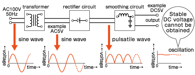
In order to actually stabilize it, finer control such as comparison with the reference power supply is required.
The second is the conversion from DC to DC of another voltage (voltage conversion). It is commonly used in electric vehicles (EVs). Basically, in-vehicle devices for automobiles are 12 V. This is because the current gasoline-fueled automobiles are equipped with a 12 V storage battery.
On the other hand, 12 V is too low for electric vehicles, and some models are currently using 280 V or 360 V (see "Battery Industry Segment is Heating Up! Power Supply and Voltage of EV Motor"). This voltage may be sufficient for the motor to drive, but since the in-vehicle device is 12 V, it is necessary to lower the voltage. This is voltage conversion.
The third is the conversion from DC to AC which is called an "inverter." In a broad sense, it may be regarded as a device that converts voltage and frequency, but in a narrow sense, it performs DC-AC conversion.
A common application involves converting DC output from residential storage batteries or solar panels into AC power compatible with commercial power grids and household outlets (see "System Interconnection to Learn from Scratch"). In addition, trains generate electricity through regenerative braking as part of energy conservation. This electricity is converted to AC power by the "inverter device for power regeneration" at the substation and used for lighting tunnels and stations. Inverters are necessary devices not only for converting to commercial AC power supplies but also for operating motors such as electric vehicles and air conditioners with high efficiency.
The fourth AC-to-AC conversion is called "frequency conversion". The largest example is for power interchange in western and eastern Japan.
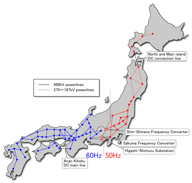
Since eastern Japan transmits power at 50 Hz and western Japan at 60Hz, frequency conversion is always required when power is exchanged between electric power companies (see "System Interconnection to Learn from Scratch").
Also, a familiar example is when you want to use imported electrical appliances in Japan. Devices from other countries must be connected by converting the voltage and frequency. In this case, as well, the voltage and frequency of the Japanese commercial power supply must be converted to the voltage and frequency used in the country where the equipment will be used (See "AC Power Supply: Fundamentals and International Differences" for the specifications of each country.).
How to Measure Voltage, Current and Power
When considering power electronics, not only maintenance and management of electrical equipment but also "power measurement," which measures the power conversion efficiency of energy-saving performance, is an important factor. There is a "power measuring instrument" for that. So how do you actually measure power?
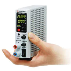
Power measuring instruments are divided into benchtop type and portable type. There are many types of benchtop types, from single-phase measurement to three-phase measurement. The power input type is roughly divided into the direct input method and the input method using the clamp current sensor. In particular, the latter can be measured in a non-contact manner. On the other hand, the portable type supports only the input method using a clamp current sensor and is suitable for portability due to its small size and lightweight.
The power measuring instrument generates an instantaneous power waveform by multiplying the input voltage waveform and current waveform. This waveform is smoothed by passing it through a low-pass filter (LPF) to obtain the active power.
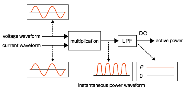
There are analog and digital methods for this arithmetic processing. In the analog method, the input signal is multiplied through an analog multiplier IC and converted to a DC voltage proportional to the active power through a low-pass filter.
On the other hand, in the digital method, the signal waveform is A/D converted once for both voltage and power. The A/D converted voltage waveform and the power waveform are averaged by digital signal processing and measured. In recent years, some power measuring instruments that perform digital processing have a harmonic analysis function. By performing sampling synchronized with the fundamental wave frequency and performing FFT analysis on the data, it is possible to obtain the harmonic components of the voltage and current, which are multiple components of the fundamental wave and perform power calculation.
Characteristics of Power Devices Such as SiC and GaN
So far, we have introduced motors and power conversion as things that can contribute to power saving. We also introduced how to measure that power. However, energy-saving does not have to be achieved only by devising circuits and structures. It is also possible to improve efficiency by replacing the material that forms the part with one that has higher electrical conductivity.
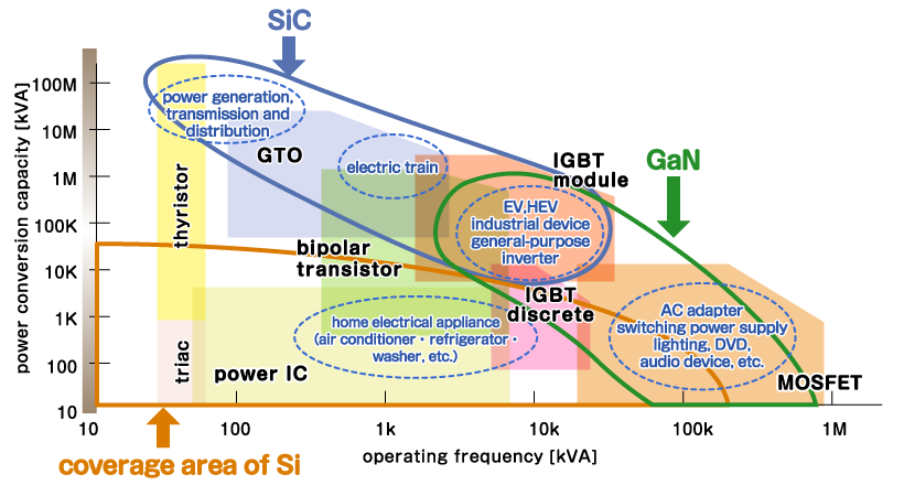
Finally, we will explain power semiconductors (power devices). Power devices include diodes, power transistors, IGBTs (Insulated Gate Bipolar Transistors), and power MOSFETs (Metal Oxide Semiconductor Field Effect Transistors). IGBTs have become widespread since the 1980s. The IGBT has the advantage of high withstand voltage performance, so in the case where a large current is passed, it has the characteristic that the power loss when it is turned on is small. On the other hand, it has the disadvantage of slower response speed than power MOSFETs. In fact, the operating range of these power devices is up to 20 kHz for conventional Si-based IGBTs and 100 kHz for power MOSFETs.
However, in order to use power more efficiently, finer control is required, and faster and larger capacity switching is also required. Devices such as GaN (Gallium Nitride) and SiC (Silicon Carbide) have been put into practical use as power devices. (See "Types of Power Semiconductors -Reliability and Performance Tests"). When using GaN or SiC, IGBTs and power MOSFETs can operate from tens of kHz to several MHz.
In the field of power electronics, we continue to promote energy savings by reviewing materials and structures from various perspectives to support the transition toward a decarbonized society.
Matsusada Precision offers a lineup of high-efficiency power supplies incorporating these advanced devices to meet demanding industrial requirements.
Related Technical Articles
Recommended products
Matsusada Precision's power supplies are the best choice for power electronics evaluation.


Reference (Japanese site)
- Japanese source page 「脱炭素社会を支えるパワーエレクトロニクスの基礎」
(https://www.matsusada.co.jp/column/power_electronics.html) - 「これでなっとく、パワーエレクトロニクス」高木茂行・長浜竜著、コロナ社刊
(https://www.coronasha.co.jp/np/isbn/9784339008982/) - 「応用から見たパワーエレクトロニクス技術最前線」菊池秀彦・川口章監修、日経BP刊
(https://bookplus.nikkei.com/atcl/catalog/20/280790/) - 「省エネモータの原理と設計法」科学情報出版株式会社刊
(https://www.it-book.co.jp/books/008.html) - 「新エネルギーの展望: パワーエレクトロニクス」 財団法人 エネルギー総合工学研究所刊
(https://www.iae.or.jp/reviews/renewable_energy_reviews/) - 一般社団法人 日本パワーエレクトロニクス協会Webサイト
(https://pwel.jp/) - 3-1-2 電力測定器(一般社団法人 日本電気計測器工業会:JEMIMA)
(https://www.jemima.or.jp/tech/3-01-02.html) - パワーエレクトロニクスの最も有名な論文の紹介
http://hirachi.cocolog-nifty.com/kh/files/20080818-1.pdf