The crest factor is the ratio of the peak value (or peak amplitude) to the Root Mean Square (RMS) value of a waveform, which is one of the quality parameters in Alternating Current (AC) power sources and Bipolar power supplies. It is sometimes called the peak factor.
In the field of electronics, it is used to describe the state of the AC power source supplied from an outlet. The crest factor is expressed as the ratio of the peak value to the rms value of the alternating current (AC) waveform.
The equation can be expressed as follows.
| Waveform | RMS value (Effective value) |
Mean value (Average value) |
Form factor | Crest factor (Peak factor) |
|
|---|---|---|---|---|---|
| DC |  |
 |
 |
 |
 |
| Sine wave |  |
 |
 |
 |
 |
| Full wave rectified sine wave |  |
 |
 |
 |
 |
| Half-wave rectified sine wave |  |
 |
 |
 |
 |
| Triangle wave |  |
 |
 |
 |
 |
| Sawtooth wave |  |
 |
 |
 |
 |
| Square wave |  |
 |
 |
 |
 |
| PWM signal |  |
 |
 |
 |
 |
|
Form Factor = RMS value / Average value Crest Factor = Peak value / RMS value |
|||||
Usually, we don't care about the current value when plugging an electric appliance into an outlet. And we are even less conscious of the crest factor. So why should we consider the crest factor?
Another indicator of AC power quality is the "Power Factor." The power factor is a measure of how much of the apparent power is used as effective power, determined by the phase difference between voltage and current and by waveform distortion. In capacitor-input circuits, which have a high crest factor, this generally leads to a lower power factor and can cause the following problems:
- Heat generation and burnout of power receiving equipment
- Malfunction of electronic equipment
- Input current increases due to higher apparent power
As you can see from the above equation, the higher the peak value of the numerator, the higher the value of the crest factor. A waveform with a high peak value occurs when the current flows in a sharp and pointed manner as shown in the figure below.
This is mainly seen when a circuit method known as a capacitor-input type is used.
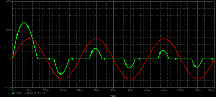
1. A sharp, spiky current causes a large current to flow into the capacitor. A capacitor subjected to a large, repetitive current can produce a humming noise, generate heat, and in some cases, burn out. This is the first problem.
2. Furthermore, a sharp and spiky current waveform contains high-frequency components.
Some electronic equipment can react to these high-frequency components and malfunction as a result.
3. A waveform with a high crest factor is characterized by a large peak current relative to its RMS value. This means that for a given amount of power, the peak current flowing through the wiring will be larger, potentially requiring thicker wires to prevent overheating and distortion of the voltage waveform.
To prevent these drawbacks, a power factor correction circuit (PFC) is used to reduce the peak current by bringing the input current closer to a sine wave.
However, the efficiency of the PFC circuit itself must be considered, so the choice involves balancing advantages and disadvantages. If you consult with our sales staff, including your operating environment and usage, we will propose a power supply that matches your needs.
Related Technical Articles
Recommended products
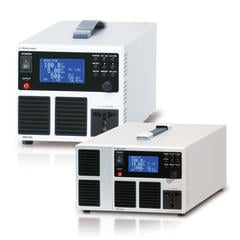
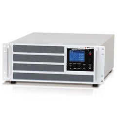
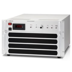
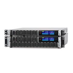
Introducing Matsusada Precision's AC power sources, bipolar power supplies, and high-voltage amplifiers


