Piezo drivers are high-voltage amplifier power supplies designed to precisely control the displacement or vibration of piezoelectric elements. Since piezo elements act as capacitive loads, optimal control requires a driver capable of both sourcing (charging) and sinking (discharging) current--unlike standard programmable DC power supplies. High-speed operation generally demands not only fast response times but also higher output current capacity.
When selecting a piezo driver, it is critical to match the specifications to the piezo element and operating conditions (waveform, frequency, and load). Driving actuators with sharp pulses can cause ringing or oscillation, potentially damaging the element. Matsusada Precision's piezo drivers are engineered to suppress these issues, ensuring stable performance across a wide range of capacitive loads.
Piezo Application Examples
Applications include X-Y stage and lens/mirror positioning, optical fiber fusion bond positioning, inkjet printer and electronic valve control, part feeder vibration, ultrasonic wave generation, and precise positioning for analyzers.
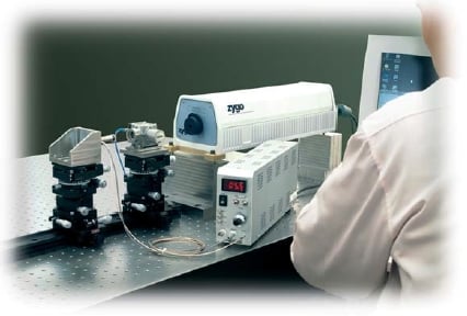
Driving microscope lenses and stages
The figure illustrates a simplified setup using a piezo driver to focus a microscope lens and position a sample stage. A 3-channel model allows for simultaneous X, Y, and Z-axis positioning with a single unit.
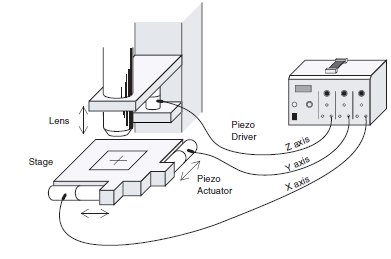
Positioning for detailed machining
The illustration shows a typical setup for high-precision metal machining using a piezo driver.
Fine adjustment of optical measuring devices
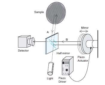
The diagram shows a Michelson interferometer used to measure the surface accuracy of lenses and mirrors.
A piezo actuator is used to make sub-micron adjustments to the mirror position for alignment.
Relationship Between Response Speed and Output Current
- When choosing a piezo driver, several key specifications must be considered. The required output voltage range (or peak-to-peak voltage) needed to achieve the desired displacement, the load capacitances of the piezo elements being driven, and the driving waveform and frequency determine the necessary output current of the driver.
Check the individual specifications for each piezo driver to choose a model that satisfies these performance conditions.
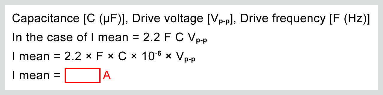
- The following formula is used to find the output current.
- For sine wave drive:
- To find the operating frequency at which each driver can be driven, the formula above is changed to f = Imean/2.2 C Vp-p
-
For pulse drive:
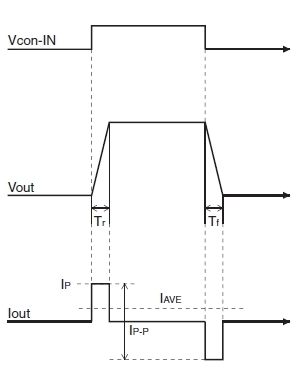
- (Note that this peak current, IP, can only be sustained for a short duration, typically 10 ms or less. Refer to the specifications for each driver.)
- To find the rise time for each driver, the formula is rearranged to Tr = (Vp-p * C) / IP. (The same applies to Tf.)
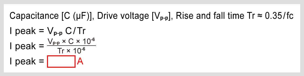
However, the actual rise time is limited by the output resistance. The estimated rise time should be the longer of the value calculated from the formula above or 3τ (approx. 95% settling time).
- Imean: Rated output current ... (A)
- IP: Peak output current ... (A)
- Vp-p: Output voltage peak-to-peak ... (V)
- R: Output resistance ... (Ω)
- C: Piezoelectric capacitance ... (F)
- Tr: Rise time ... (S)
- Tf: Fall time ... (S)
- 3τ: Approx. 95% setting time ... (S)
Function for Increasing Peak Power
This function is supported on all Matsusada piezo drivers, allowing for an output peak current of approximately 3 times the rated current. This enables high-speed startup even with compact drivers in applications with low repetition rates (low average power). For example, the PZJ-0.1Px3 is rated at 300 mA but can supply a peak current of 900 mA. If the average output current remains within 300 mA, the unit can operate as a ±900 mA power supply (see Fig. 2). With this capability, a 100 V output can drive a 1 µF piezo element with a rise time of 0.11 ms.
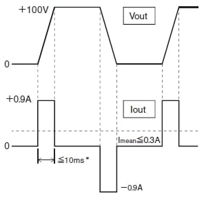
* Pulse width of current is within 10 ms.
Bias Function
The bias function is an extremely convenient feature that allows a DC offset to be superimposed on the output voltage. By using the dial on the front panel to set the bias, you can move the output waveform freely within the rated output range. (See Figures (a) and (b) below.) If the resulting waveform (signal plus bias) exceeds the rated output range, the output will be clipped. (See Figure (c) below.)
By using the bias function, it is possible to directly change the displacement reference position of the piezo element without changing the control voltage, which is effective for position adjustment and DC operation.
Although the PZM series, PZM-B(0.3) series, and PZM-B series do not feature an internal bias adjustment knob, a bias voltage can still be applied by adding a DC offset to the external control signal.
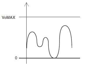
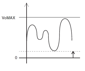
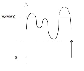
Fig. 3 Explanation of Bias Function
Related Technical Articles
- Application: Piezo Driver
- Amplifier Basics: Principles, Operation, and Key Considerations
- Safety and Usage of High Voltage Power Supply
- What are Piezoelectric Devices? Principles, Structure, and Applications Explained
- Application: Piezoelectric device (Piezo Device)
- Proper Usage Guidelines for Piezoelectric Actuators
- What is a Piezo Actuator? (Basic Knowledge)
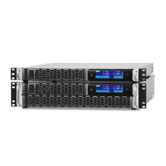
Recommended products
Matsusada Precision provides precision control solutions with piezo actuators and piezo drivers.