Published: , M.P.
/ Updated: , T.N.
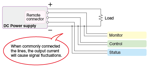
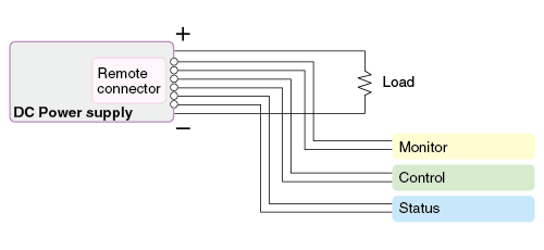
Wiring Connections
- Separate Ground Lines: Do not share a common ground (GND) between signal lines, power lines, and status output lines.
- Minimize Cable Length: Keep remote control wiring as short as possible to reduce noise pickup.
- Route Separately: Route remote signal lines away from high-frequency power cables and switching noise sources.
Monitoring and Output Impedance
- Impact of Input Impedance: The measured voltage can vary depending on the input impedance of the external measuring device (e.g., multimeter or data logger) connected to the power supply. Higher input impedance results in higher measurement accuracy.
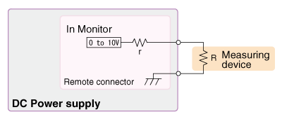
| r (Output impedance) |
R (Input impedance by measuring instrument) |
Deviation |
|---|---|---|
| 1 kΩ | 10 kΩ | 10% |
| 1 kΩ | 100 kΩ | 1% |
| 1 kΩ | 1 MΩ | 0.1% |
Analog Remote Control Methods
1. External Voltage Control (Voltage / Current / OVP / OCP)
In this mode, the power supply output is controlled by an external DC voltage source. Applying 0 V to 10 V to the remote control terminal adjusts the output from 0 to the maximum rated value.
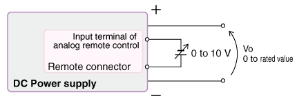
| Analog remote control input | Power supply output | |
|---|---|---|
| CV, CC, OVP, OCP |
0 to 10 V | 0 to rated value |
2. External Resistance Control (Normal & Fail-Safe Logic)
Output can be controlled by connecting an external variable resistor (potentiometer) or fixed resistors. There are two control logic types usually available:
- Normal Logic (0 to 10 kΩ): Adjusting the resistance from 0 to 10 kΩ increases the output from 0 to the maximum rated value.
- Fail-Safe Logic (10 kΩ to 0): Adjusting the resistance from 10 kΩ to 0 increases the output. This is often preferred for safety; if the control wire breaks (infinite resistance), the output drops to zero.
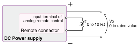
| Analog remote control input | Fail-safe mode | Power supply output |
|
|---|---|---|---|
| CV, CC | 0 to 10 kΩ | 10 kΩ to 0 | 0 to rated value |
3. External Resistance Control (Using Internal Reference)
This method uses an external potentiometer connected to the power supply's internal reference voltage source. This eliminates the need for an external power source for control signals.
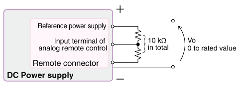
| Analog remote control input | Output | |
|---|---|---|
| CV, CC | 0 to 10 kΩ | 0 to rated value |
Related Technical Articles
Recommended products
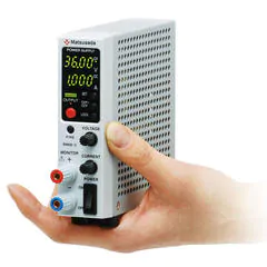
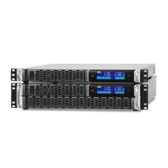
Matsusada Precision's high-performance power supplies