The global surge in demand for electric vehicles (EVs) is reshaping the automotive industry. The EV category encompasses various architectures, primarily Battery Electric Vehicles (BEVs), Hybrid Electric Vehicles (HEVs), Plug-in Hybrid Electric Vehicles (PHEVs), and Fuel Cell Electric Vehicles (FCEVs). This article specifically focuses on BEVs and PHEVs--vehicles requiring external charging--and explores their power system architecture and different power source configurations. This guide offers critical insights for engineers aiming to deepen their understanding of EV power systems and discover robust testing solutions for their applications.
Charging Methods for EVs
BEVs and PHEVs rely on external power sources for charging. BEVs run exclusively on electric power to drive their motors, offering the key advantage of zero carbon emissions during operation. PHEVs combine an engine and an electric motor, switching between the two depending on driving conditions. These vehicles utilize two sources of electrical power: regenerative energy captured during deceleration and electricity from external charging sources.
EV charging is broadly categorized into two main methods: standard charging and rapid charging.
Level 1 and Level 2 EV charging (AC Charging)
Standard charging, also known as AC charging, utilizes widely available AC power. This ranges from standard household outlets (100-120 V, Level 1) to dedicated higher-voltage circuits (200-240 V, Level 2). Because EV batteries require DC power, the vehicle's Onboard Charger (OBC) converts the incoming AC power to DC to charge the battery.
In Japan and the United States, standard charging connectors comply with SAE J1772 and IEC 62196-2 Type 1 specifications. The primary advantage of standard charging is its versatility it can be installed both at homes and in locations without access to commercial power infrastructure. Its cost is relatively affordable, ranging from low-cost household adapters to more substantial investments for dedicated charging units.
The primary drawback, however, is slower charging speed. A complete charge from an empty battery can take up to 12 hours.
| Country | Japan | America | Europe, rest of world | China |
|---|---|---|---|---|
| Type |
 J1772, Type 1 |
 Mennekes, Type 2 |
 GB/T |
Level 3 Rapid EV Charging (DC Charging)
Rapid charging, also known as DC charging, delivers high-power direct current directly to EVs. At rapid charging stations, AC power (200V or 400V) is converted to DC, supplying vehicles with 400V or 500V DC. In Japan, rapid charging connectors adhere to the CHAdeMO standard.
Rapid charging infrastructure requirements are substantial, typically involving a three-phase 200V or 400VAC power supply, often requiring commercial-grade electrical installations or transformer units. Installation costs are significant--often requiring substantial capital investment for the unit and infrastructure--making it impractical for residential use.
The main advantage of rapid charging is its speed, allowing most vehicles to reach a full charge in 30 minutes or less. This makes rapid charging ideal for public spaces such as highway service areas and commercial facilities, where drivers need quick recharging during their journey.
| Country | Japan | North America | Europe, Rest of World | China | |
|---|---|---|---|---|---|
| Type |
 CHAdeMO |
 CCS1 |
 Tesla |
 CCS2 |
 GB/T |
EV Architecture
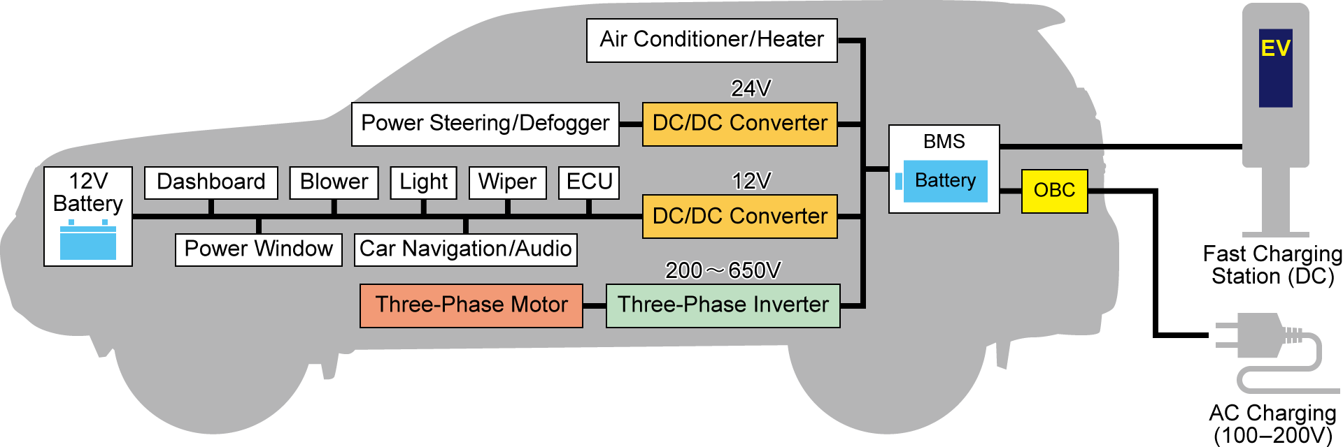
EVs incorporate complex interconnected systems responsible for propulsion, control, and various other functions. Although many of these systems resemble those in conventional vehicles, the charging system is unique to EVs. This chapter explores the architecture of EV charging systems.
Overview
An EV's charging system consists of five key components:
Batteries
Features of EV Batteries
In EVs, the battery serves as the primary energy storage system, functioning similarly to the fuel tank in conventional gasoline vehicles. Beyond storing energy for vehicle operation, EV batteries also capture and store regenerative energy produced during deceleration. The dominant technology in EV batteries is lithium-ion, with most manufacturers favoring a ternary (NMC) system utilizing nickel, manganese, and cobalt as cathode materials.
Due to cobalt's high cost, interest in lithium iron phosphate (LFP) batteries is increasing. While LFP batteries offer superior safety and cost advantages, their main drawback is reduced performance in low-temperature environments. EV batteries are notable for their substantial capacities, with typical 2025 models ranging from 40 to 60 kWh, although some high-end vehicles exceed 100 kWh. As environmental awareness grows and EV adoption expands, battery capacities continue to trend upward, suggesting future models will likely feature even larger batteries.
Lithium-ion batteries for EVs are available in several form factors, including 18650, 21700, 4680 cylindrical, pouch, and prismatic designs, with manufacturers selecting specific types based on their vehicle platforms and requirements. Each EV battery system includes a battery management system (BMS), which monitors battery status, regulates charging and discharging operations, and implements protective measures to optimize battery life and safety.
EV Battery Testing
A key challenge for EV batteries is their exposure to extreme operating conditions. Since vehicles operate outdoors in diverse global regions, batteries must function reliably at temperatures ranging from −40°C to +80°C. Battery evaluation encompasses both electrical and physical testing.
Electrical testing includes repeated charge-discharge cycles under specific temperature conditions, impedance measurements, short-circuit testing, and voltage tolerance tests at high and low extremes. These evaluations require specialized equipment such as high-voltage power supplies, impedance measurement devices, and regulated AC/DC power supplies.
Given the demanding automotive environment, batteries must also undergo physical testing. This includes drop impact tests, vibration resistance testing, crush resistance evaluations, and nail penetration tests to ensure safety and performance under real-world conditions.
Onboard Charger (OBC)
Understanding the OBC
The OBC is a crucial component used during Level 1 and Level 2 AC charging, although it is not involved in rapid charging operations. Since batteries can store only direct current electricity, the AC power supplied by charging stations must be converted to DC within the EV. The OBC performs this essential function, converting AC power to DC and adjusting the voltage to suitable levels for battery charging. In essence, the OBC serves as an AC/DC converter.
While Level 2 charging stations can deliver up to 7.2 kW (240 V AC × 30 A), the actual charging speed is limited by the OBC's conversion capacity. For instance, if an OBC has a maximum conversion power of 3.6 kW, the charging station's effective output will be restricted to 3.6 kW (240 V AC × 15 A), resulting in longer charging times regardless of the station's capabilities.
OBC Components
The OBC consists of the following key components:
- Input noise filter
- Rectifier circuit (AC/DC conversion)
- Voltage conversion circuit
- Output noise filter
The input noise filter eliminates electrical interference present in power received from sources such as household outlets. The rectifier circuit then converts this AC power to DC, while the voltage conversion circuit adjusts it to an appropriate level for battery charging. Finally, the power passes through the output noise filter to remove any interference generated during the conversion process before being delivered to the battery.
OBC Testing Methods
OBC testing encompasses two main aspects: input (AC) side and output (DC) side testing. Input-side evaluation simulates various power supply conditions encountered during charging, including undervoltage scenarios, voltage distortion, momentary power interruptions, voltage sags, and fluctuations. This testing requires specialized equipment such as AC power supplies and high-power bipolar power supplies, with particular attention given to performance under challenging phase conditions.
Output-side evaluation focuses on long-term reliability through aging tests and transient response measurements. This testing uses specialized equipment such as battery simulators and regenerative DC power supplies (regenerative electronic loads) to assess the OBC's performance characteristics under various operating conditions.
Inverters
Characteristics of EV Inverters (traction inverter)
A traction inverter is a device that converts DC power to AC power. General-purpose inverters sometimes refer to devices that internally convert AC power to DC, adjust the voltage, and then convert it back to AC output (effectively combining inverter and converter functions in one unit). In contrast, EV inverters specifically convert DC power from the battery to AC power.
EVs use brushless motors due to their high-power output capability, which necessitates AC power. Since the battery supplies DC power, an inverter is essential to convert this power into AC for the motor. Additionally, EVs employ bi-directional inverters to enable regenerative power capture during deceleration, sometimes included in the broader definition of the inverter system.
EV traction inverters require three key characteristics: high power density, exceptional thermal management, and a compact, lightweight design. As the demand for EVs grows and their applications expand, there is an increasing need for higher battery capacities and motor outputs. This trend accelerates the innovation of more powerful and efficient inverters. Additionally, these components must withstand harsh operating conditions unique to automotive applications while remaining compact and lightweight to maximize vehicle range.
Inverter Structure
The inverter's core component is its voltage conversion circuit, which in EVs primarily utilizes switching circuits for power conversion. These switching circuits achieve high power conversion efficiency through rapid ON/OFF switching of circuit elements, mainly using field-effect transistors (FETs) as switching components.
Inverter Testing Methods
Traction inverter evaluation encompasses several critical aspects of performance testing. Power loss measurement during switching operations is particularly important as efficiency becomes increasingly crucial with higher power requirements. Engineers evaluate these losses by analyzing voltage-current products during switching transitions (turn-ON/OFF periods), requiring high-resolution oscilloscopes for precise measurements.
Surge testing is another vital aspect of evaluation. It examines how the inverter responds to voltage surges caused by peripheral circuit wiring inductance and assesses its ability to protect connected equipment. This testing requires both high-resolution oscilloscopes and high-voltage power supplies to simulate real-world conditions and verify protection mechanisms.
DC/DC Converter
Understanding DC/DC Converters in EVs
While AC/DC power supplies (rectifiers) convert AC power from the grid to DC, the DC/DC converter within an EV serves a different function: it steps down the high-voltage DC power from the main battery to lower voltages.
The primary power consumer in an EV is its drive motor, which requires high voltage for optimal performance and efficiency. Consequently, the main battery system operates at high voltage levels. However, EVs also require power for numerous other systems besides the drive motor. These include auxiliary systems such as air conditioning and power windows, as well as various control units throughout the vehicle. Since these components operate at significantly lower power levels than the main drive motor, they cannot directly use the high-voltage power from the battery system. The DC/DC converter plays an essential role here, precisely stepping down the high-voltage DC power from the main battery to the stable, lower voltages required by these auxiliary systems and control units.
DC/DC Converter Testing Methods
The evaluation of EV DC/DC converters utilizes a comprehensive testing setup that includes high-voltage DC power supplies, high-power electronic loads, regenerative DC power supplies, and bipolar power supplies connected to the converter. The high-voltage DC power supply simulates battery output under various operating conditions, while high-power electronic loads emulate power consumption patterns of vehicle systems such as air conditioning, power windows, and various control units, including their complex operational interactions. This testing configuration allows engineers to replicate numerous operational scenarios and verify the converter's behavior and performance under each specific condition.
Electric motors
Characteristics of EV Motors
AC motors are used in EVs. There are four main types of AC motors used in EVs:
- Permanent Magnet Synchronous Motor (PMSM)
- Electrically Excited Synchronous Motor (EESM)
- Switched Reluctance Motor (SRM)
- Induction Motor (IM)
PM motors use permanent magnets in the rotor and are also known as DC brushless motors. PM motors are classified into two types: SPM, with permanent magnets on the rotor surface, and IPM, with permanent magnets inside the rotor. IPM motors using high-performance neodymium magnets are commonly employed in EVs. PM motors are characterized by their high efficiency and long service life.
EESMs generate magnetic force by passing current through windings. Due to copper losses in the windings, they face efficiency challenges. SRMs use a ferromagnetic iron core in the rotor. They have a simple structure and circuitry, offering advantages in cost-effectiveness and reliability. However, SRMs face ongoing challenges related to efficiency and noise control.
IMs are asynchronous motors that use three-phase AC power. Since IMs do not use magnets, they require no rare earth elements or rare metals, attracting attention for reduced vulnerability to global supply chain disruptions. However, IMs experience copper losses, making efficiency an ongoing challenge.
Motor Testing Methods
EV motor testing employs evaluation benches (dynamometers) to simulate actual road-driving loads. These tests measure critical parameters such as rotational speed, torque, efficiency, vibration, and noise levels. The evaluation also includes magnetic loss analysis and power consumption assessment during each rotation cycle. These tests require high-voltage AC power supplies capable of simulating various battery conditions and driving scenarios to power the motor.
e-Axle: Core component of EVs
An eAxle integrates a motor, inverter, and reduction gear into a single unit. Drawing a parallel with conventional vehicles, it's comparable to combining an engine and transmission into one assembly. By integrating these three components, eAxles achieve significant reductions in size and weight compared to traditional configurations.
eAxle evaluation necessitates simultaneous testing of all three components using a dynamometer setup similar to standard motor testing. While the evaluation parameters remain consistent with motor testing -measuring output speed, torque, hydraulic pressure, vibration, and noise- the power source differs. Due to the integrated inverter design, eAxle testing utilizes a DC battery simulator rather than an AC power supply.
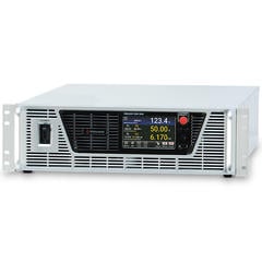
Matsusada Precision's Regenerative DC Power Supplies
Matsusada Precision's regenerative power supplies play a vital role in the development and production-line testing of EV components, including batteries, OBCs, inverters, and converters. Below is an introduction to their PBR/PBRM series regenerative power supplies.
Key Applications
The PBR/PBRM series integrates a high-performance DC power supply and a regenerative electronic load into a single unit. This design makes the series suitable for diverse applications, including AC/DC converter evaluation, large-capacity battery charge/discharge testing, inverter and motor assessment, and OBC evaluation.
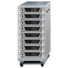
Space-Efficient Design
By combining these capabilities, the PBR/PBRM series eliminates the need for separate instruments, significantly reducing the equipment footprint. This space-efficient design optimizes laboratory layouts, allowing for the integration of additional instrumentation.
Comprehensive Product Range
The PBR/PBRM series offers a diverse lineup of over 60 models, with power ratings ranging from 5 kW to 150 kW. This extensive range enables customers to select the optimal model that precisely matches their specific applications and technical requirements.