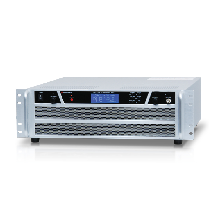
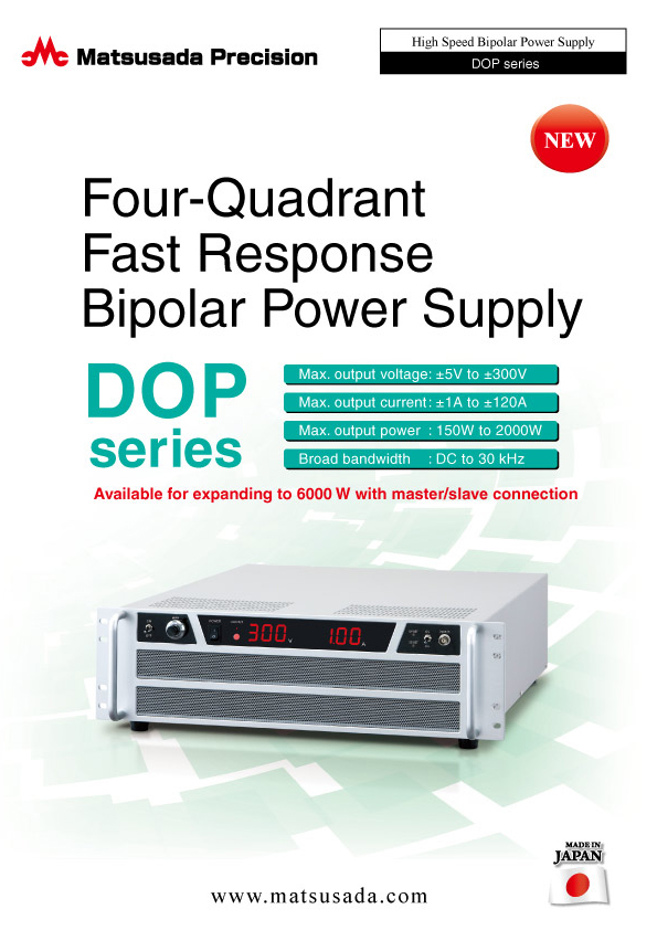
FOUR-QUADRANT FAST RESPONSE BIPOLAR POWER AMPLIFIER
High speed bipolar power amplifier
- Voltage range: ±5 to ±300V
- Current: ±1 to ±120A
- Power: 150 to 2000W
- Broad bandwidth:
DC to 30 kHz
AVAILABLE FOR EXPANDING TO 6 KW WITH MASTER-SLAVE CONNECTION
DOP series are four-quadrant bipolar power supplies that source and sink electric power. You can use them in 2 modes a CV (Constant Voltage) or a CC (Constant Current). The weight is half of the conventional units by adopting the aluminum frame.
They are compact and high speed, driving output proportional to the input waveform such as a sine wave, triangular wave, saw wave, and square wave.
DOP series is most appropriate for inductive load including coil and transformer, capacitive load like a capacitor, a test of DC servo motor or automobile electric appliances, and surface treatment.
All the models are completely solid-state with output voltage between ±5 V and ±300 V.
Note: This product is not designed for charge and discharge of battery.
For battery charging and discharging applications, please refer to the Battery Cycle Tester product page.
FEATURES AND BENEFITS
- Response speed
- Newly developed DOP series is the most appropriate for transient response test with such high power and broad bandwidth.
- Wide range of products
- Select a model fitting for your applications from our wide range of output voltage and current.
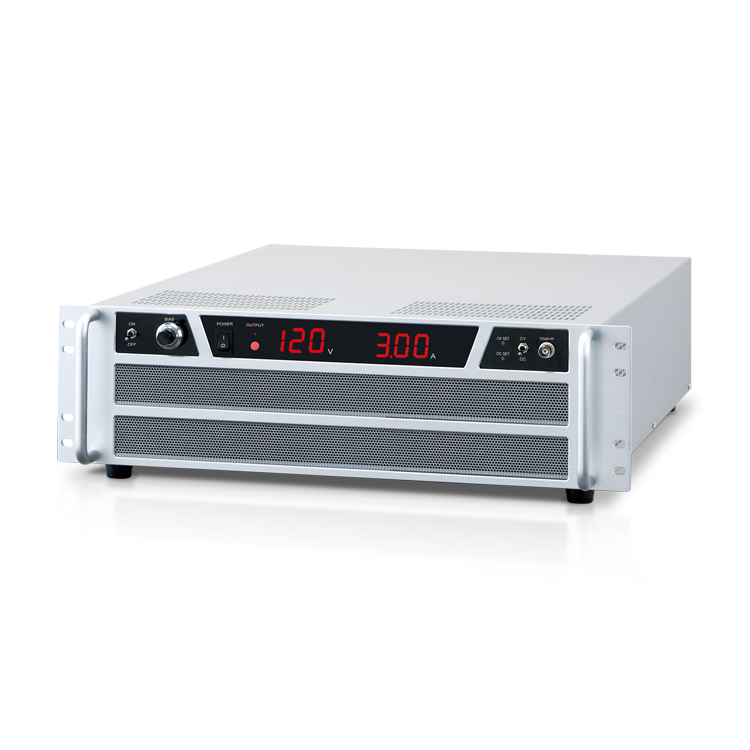
- DC bias
- 10-turn potentiometer to be used for the output setting volume when used as the DC power supply and for the bias setting when used as AC power supply is equipped.
- Silent operation
- Operating noise became quiet by having employed the silent fan, and also it became easy to use.
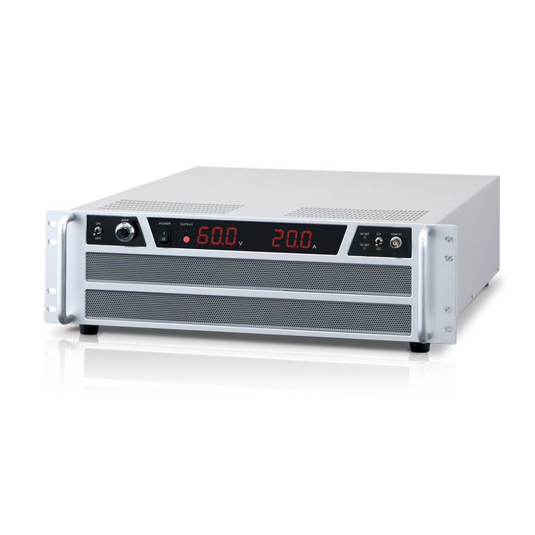
- DC output meter
- 3-digit digital meter displays the DC value of the output voltage and current. (The option of rms indication is available.)
- Four-quadrant action
- DOP series can be used both as a high speed response DC power supply and as a DC electronic load.
- Constant voltage (CV)/Constant current (CC)
- A single switch selects between CV and CC modes.
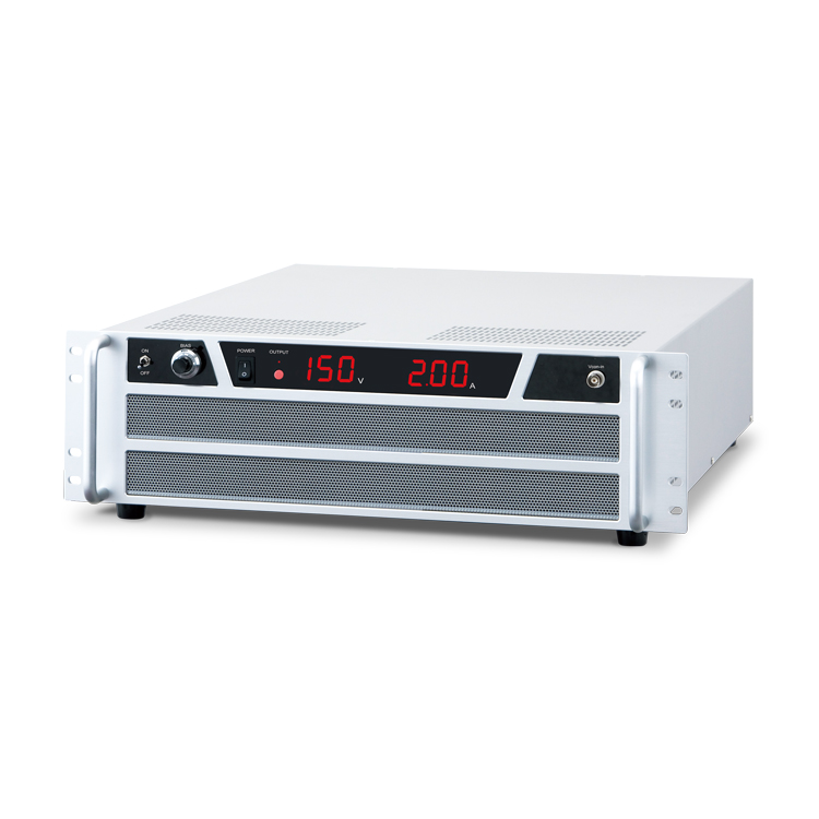
- Compact & Lightweight
- For maximum compactness and lightweight, the DOP series has been improved for a small footprint and easy carry.
- Complete protective function
- Protective function against overvoltage/overcurrent and protective measures against output short-circuit are completely provided.
- Master-Slave
- The option of Master/Slave control will resolve power shortages.
APPLICATIONS
- Inductive load such as coil and transformer
- Capacitive load such as electric double-layer capacitor
- Voltage regulation tests for in-vehicle electrical component
- Evaluation test for solar panel related devices
- Various motor tests
- For surface treatment
Models
* Models with voltage, current, or frequencies not listed here are also available. Please contact the nearest sales office.
| Model | Maximum output | Frequency response (-3 dB) | ||
|---|---|---|---|---|
| Voltage | Current | Power | ||
| DOP5-30 | ±5 V | ±30 A | 150 W | DC to 20 kHz |
| DOP5-60 | ±60 A | 300 W | DC to 20 kHz | |
| DOP6-120 | ±6 V | ±120 A | 720 W | DC to 20 kHz |
| DOP10-15 | ±10 V | ±15 A | 150 W | DC to 20 kHz |
| DOP10-30 | ±30 A | 300 W | DC to 20 kHz | |
| DOP10-60 | ±60 A | 600 W | DC to 20 kHz | |
| DOP20-7.5 | ±20 V | ±7.5 A | 150 W | DC to 20 kHz |
| DOP20-15 | ±15 A | 300 W | DC to 20 kHz | |
| DOP20-30 | ±30 A | 600 W | DC to 20 kHz | |
| DOP20-60 | ±60 A | 1200 W | DC to 20 kHz | |
| DOP20-100 | ±100 A | 2000 W | DC to 20 kHz | |
| DOP25-6 | ±25 V | ±6 A | 150 W | DC to 30 kHz |
| DOP25-12 | ±12 A | 300 W | DC to 30 kHz | |
| DOP25-24 | ±24 A | 600 W | DC to 20 kHz | |
| DOP25-48 | ±48 A | 1200 W | DC to 20 kHz | |
| DOP25-80 | ±80 A | 2000 W | DC to 20 kHz | |
| DOP30-40 | ±30 V | ±40 A | 1200 W | DC to 20kHz |
| DOP45-3.3 | ±45 V | ±3.3 A | 150 W | DC to 20 kHz |
| DOP45-6.6 | ±6.6 A | 300 W | DC to 20 kHz | |
| DOP45-13.3 | ±13.3 A | 600 W | DC to 20 kHz | |
| DOP45-16 | ±16 A | 720 W | DC to 20 kHz | |
| DOP45-26.7 | ±26.7 A | 1200 W | DC to 20 kHz | |
| DOP45-44.4 | ±44.4 A | 2000 W | DC to 20 kHz | |
| DOP60-2.5 | ±60 V | ±2.5 A | 150 W | DC to 20 kHz |
| DOP60-5 | ±5 A | 300 W | DC to 20kHz | |
| DOP60-10 | ±10 A | 600 W | DC to 20 kHz | |
| DOP60-20 | ±20 A | 1200 W | DC to 20 kHz | |
| DOP60-33.3 | ±33.3 A | 2000 W | DC to 20 kHz | |
| DOP70-17 | ±70 V | ±17 A | 1200 W | DC to 20 kHz |
| DOP80-25 | ±80 V | ±25 A | 2000 W | DC to 20kHz |
| DOP120-2.5 | ±120 V | ±2.5 A | 300 W | DC to 20 kHz |
| DOP120-5 | ±5 A | 600 W | DC to 20 kHz | |
| DOP120-10 | ±10 A | 1200 W | DC to 20 kHz | |
| DOP150-2 | ±150 V | ±2 A | 300 W | DC to 20kHz |
| DOP150-4 | ±4 A | 600 W | DC to 20 kHz | |
| DOP150-8 | ±8 A | 1200 W | DC to 20 kHz | |
| DOP200-1.5 | ±200 V | ±1.5 A | 300 W | DC to 20 kHz |
| DOP200-1.75 | ±1.75 A | 350 W | DC to 20 kHz | |
| DOP200-3 | ±3 A | 600 W | DC to 20 kHz | |
| DOP200-3.5 | ±3.5 A | 700 W | DC to 20 kHz | |
| DOP200-6 | ±6 A | 1200 W | DC to 20 kHz | |
| DOP300-1 | ±300 | ±1 A | 300 W | DC to 20 kHz |
| DOP300-2 | ±2 A | 600 W | DC to 20 kHz | |
| DOP300-4 | ±4 A | 1200 W | DC to 20 kHz | |
Functions
Protections
OVP (Overvoltage protection)
DOP series is equipped with overvoltage protection, which protects load by limiting voltage up to approx. 110% of the rated output voltage even at abnormal conditions.
* -LVc option (output voltage limiter) enables to control of the output in 0 to approx. 110% range.
OCP (Overcurrent protection)
DOP series is also equipped with overcurrent protection, which protects power supplies and load by limiting current up to approx. 110% of the rated output current.
* -LCc option (output current limiter) enables to control of the output in 0 to approx. 110% range.
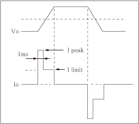
High speed overcurrent protection
DOP series is provided with 2 types of overcurrent protections, high speed overcurrent protection to limit the pulse current, and standard overcurrent protection to limit the static current.
The standard overcurrent protection limits the static current, responding at around 1 ms. Additional high speed overcurrent protection can limit the pulse current of square waveforms or from capacitor at approx. 2 times more current of rating.
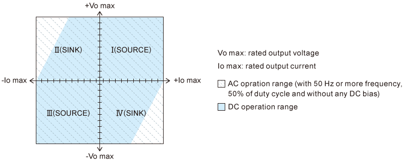
Output range
DOP series is a bipolar power supply which can perform four quadrant operation. They can supply (source) and absorb (sink) current in the field of the drawing on the right.
CV/CC setting selection
Inputting voltage via Vcon-in enables the control of output voltage V when CV control is selected and output current A when CC control is selected.
| in CV mode | in CC mode | |
|---|---|---|
| Vcon | Output voltage | Output current |
| -10 V | -Rating | -Rating |
| 0 V | 0 V | 0 A |
| +10 V | +Rating | +Rating |
Use of BIAS
When the "BIAS ON/OFF switch" is flipped to ON, bias can be changed with the "BIAS setting dial." Bias of the voltage can be set when CV control is selected, and that of the current can be when CC control is selected.
| in CV mode | in CC mode | |
|---|---|---|
| Scale | Output voltage | Output current |
| 000 (ccw) | -Rating | -Rating |
| 500 | 0 V | 0 A |
| 1000 (cw) | +Rating | +Rating |
Specifications
Options
- -LCc
Output current limit
- Variable from 0 to approx. 110% with front panel dial
- -LF
Floating ground (withstand voltage 200 Vdc)
- -LMsm, -LMss
Master/slave control (parallel operation)
- Maximum three units including the master unit are hooked. "-LMsm" for the master unit and "-LMss" for slave units. Please order the required number of units.
Every master unit and slave units are exclusive use, but operating individually is also available. If you want to change the master-slave combination, it will need to be readjusted at our factory.
- -LN
Output state auto-recovery (former: no power failure protection)
- This option retains the output state when recovering from an input power interruption, such as an AC power switch ON/OFF or a power failure. Therefore, there is no need to reset the protection status by turning off the OUTPUT switch once.
Caution: If you turn on the power while the OUTPUT setting is ON, the output will be ON.
- -LPr
rms display
- -LVc
Output voltage limit
- Variable from 0 to approx. 110% with front panel dial
- -L(220V)
200 Vac to 240 Vac ±10% single phase, 50 Hz/60 Hz input
- (150 W models and 300 W to 350 W models only)
How to Order
When ordering, add Option No. in the following order by alphabet, and number to Model No.
[Example] DOP25-12-LCcFMsmNPrVc(220V)
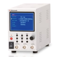
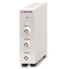
Accessories
Function Generator


Dimensions
Tech Notes
Characteristic of amplifier
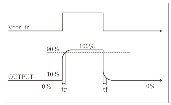
Rise time
(Stepping time): The response time is sometimes described by the rise time (as shown in the drawing on the right).
The rise time of an amplifier at a response speed of (= frequency bandwidth)
Fc (Hz) is generally acquired by "tr ≒ 0.35/fc."
Fall time tf is the same as tr.
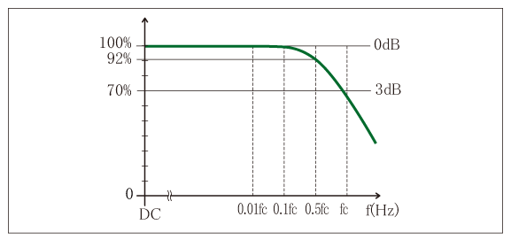
Frequency bandwidth
: at 30 kHz or lower, tr = tf = around 12 μs
: at 20 kHz or lower, tr = tf = around 18 μs
Response speed
When accurate output waveforms are required, select an amplifier with a frequency bandwidth higher enough than the operating frequency. In the case of using sine waves, 3 times to 5 times more frequency bandwidth is required, and around 10 times more in the case of square waves in general. Inadequate bandwidth causes not only a decrease in the output amplitude but much difference between the input and output phases. Therefore operating the product while monitoring the actual output waveforms is recommended.
Inductive load
Some inductance of inductive load may cause resonance in CC mode.
In such cases, connect a C-R series circuit between output terminals to prevent resonance.
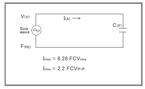
Capacitive Load
When a capacitive load is more than 100 pF (including a stray capacitance of output wire), the resonance in the output may occur. In that case, install 100-ohm (@0.1 μF) to 1000-ohm (@1000 pF) of high voltage resistance in the output in series. Please note that the frequency band will be limited as the formula written in the right figure when an amplifier is used with a capacitive load.
In addition, when an amplifier is used for use, such as a corona discharge, the current which is higher than the rating will flow, and it will affect the amplifier badly. In this case, as well as the time to use an amplifier with a capacitive load, please install the output resistance and limit the current.
* Please avoid continuous inputting of high frequency signal which reduces the output frequency of an amplifier. An amplifier will be broken because of an increase of internal loss.
Download
If you are unable to download a file
Please try the following solution.
- Please press Ctrl+F5 to clear the cache of your web browser and try again.
- Please restart your web browser and log in again to try again.
- Please change your web browser to another browser and try again.
- Restart the computer and try again.
- Please try again on a different computer.
-
DOP series Datasheet
Date: 2023-07-26 rev.19
PDF (2,401 KB)
-
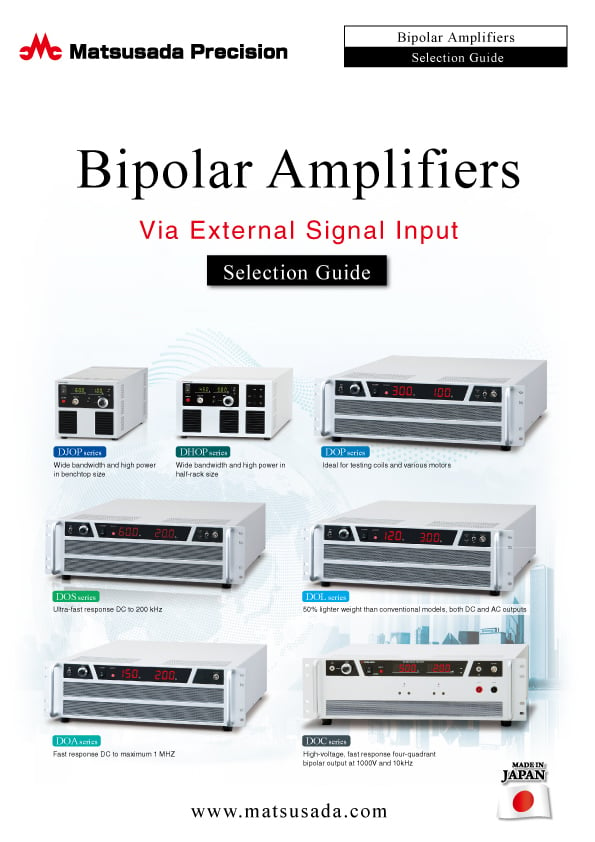
Bipolar Power Supplies Selection Guide Via External Signal input
Date: 2023-07-26 rev.05
PDF (5,471 KB)
-
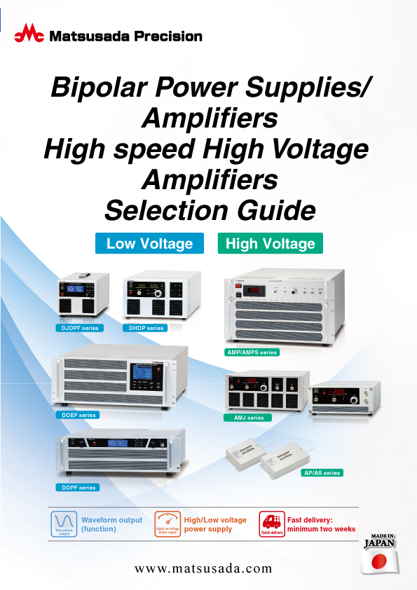
Bipolar Power Supplies/Amplifiers Selection Guide
Date: 2023-10-17 rev.03
PDF (6,310 KB)

-
DOP series Instruction Manual
Date: 2023-4-11 rev.3.6
PDF (1,270 KB)
The account registration is necessary for downloading
-
DOP series Datasheet
Date: 2023-07-26 rev.19
PDF (2,401 KB)
-
Bipolar Power Supplies Selection Guide Via External Signal input
Date: 2023-07-26 rev.05
PDF (5,471 KB)
-
Bipolar Power Supplies/Amplifiers Selection Guide
Date: 2023-10-17 rev.03
PDF (6,310 KB)
-
DOP series Instruction Manual
Date: 2023-4-11 rev.3.6
PDF (1,270 KB)
In this website, we provide only the latest version of information including instruction manuals as of our products. Therefore, the newest versions of manuals on the website might be not same as the ones of products you purchased in the past.