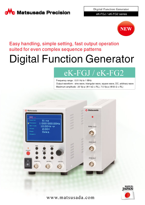
Digital Function Generator
Fast waveform output operation suited for even complex programming patterns
- Frequency range:
0.01Hz to 1MHz - Maximum amplitude:
20Vp-p (@1kΩ = RL)
7.5Vp-p (@50Ω = RL) - Easy handling
- Simple setting
Simple operation and high stability, the benefit of digital function generator
eK-FGJ is a function generator designed for realizing smaller and more user-friendly units. The output value from the function generator can be converted and set based on our bipolar power supplies. Accordingly, the eK-FGJ features an accurate and intuitive setting without calculating the gain value.
We implemented the operability improvement by simple operation on the 3.5-inch LCD screen. As you know, the function generator usually creates a stable waveform with high accuracy.
Features
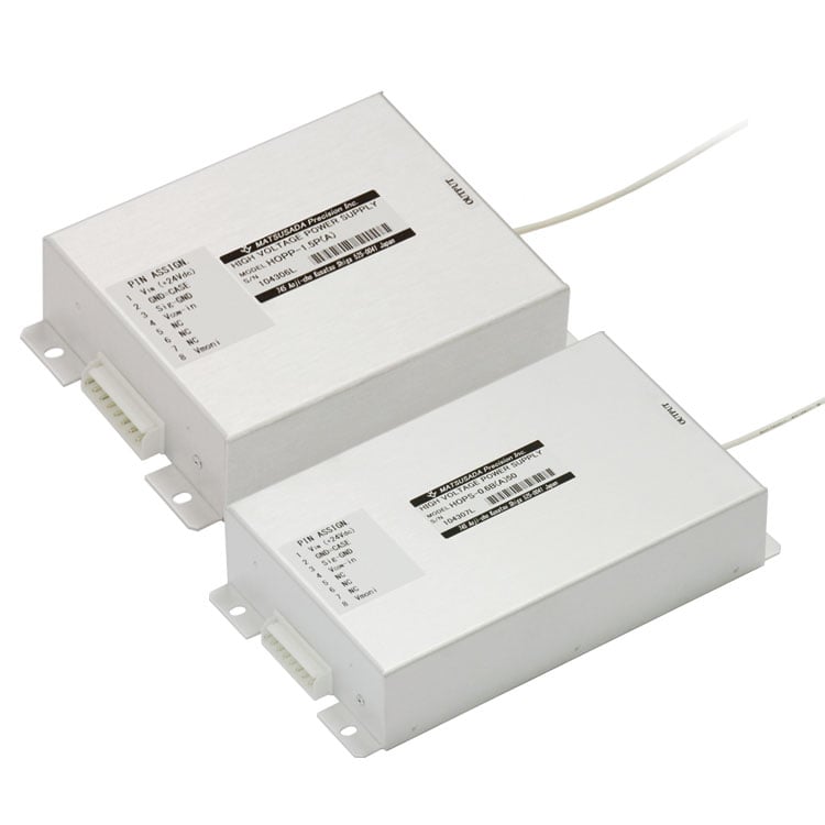
- Designed for directly setting the output from bipolar power supplies produced by Matsusada Precision.
- High accuracy and stability features for signal creation
- Intuitive operation and setting on LCD screen in a single unit
- Programming operation with control software
- Easy operating exclusive control software as standard equipment
Model
| Model | Frequency range | Number of channels | Maximum amplitude | Offset | Output impedance |
|---|---|---|---|---|---|
| eK-FGJ | 0.01 Hz to 1 MHz | 2 | 20 Vp-p (@1 k Ω = RL), 7.5 Vp-p (@50 Ω = RL) |
+ / -10 V (no load) | 50 Ω |
Functions
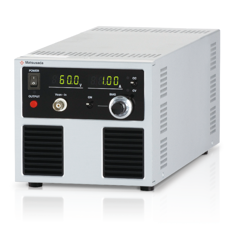
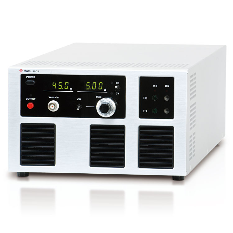
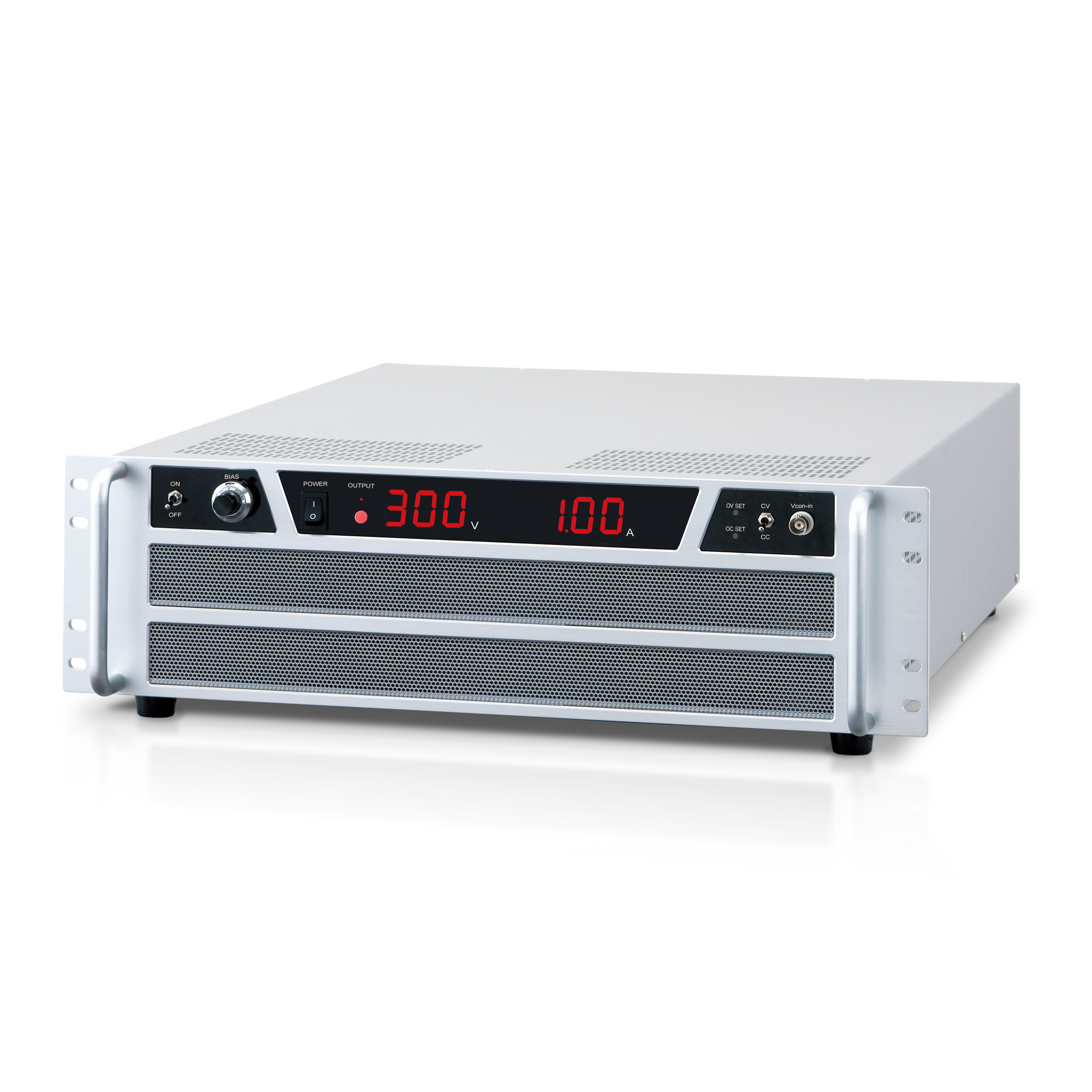
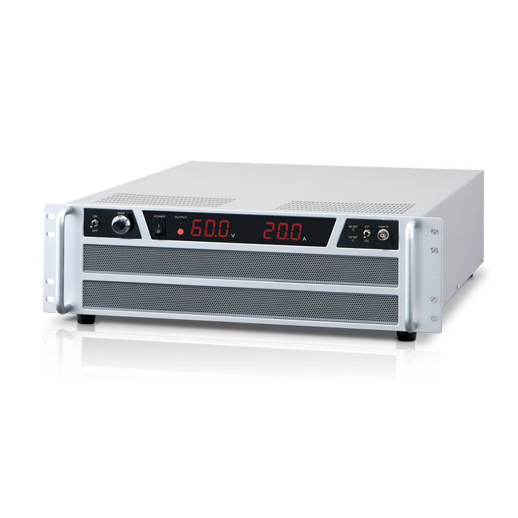
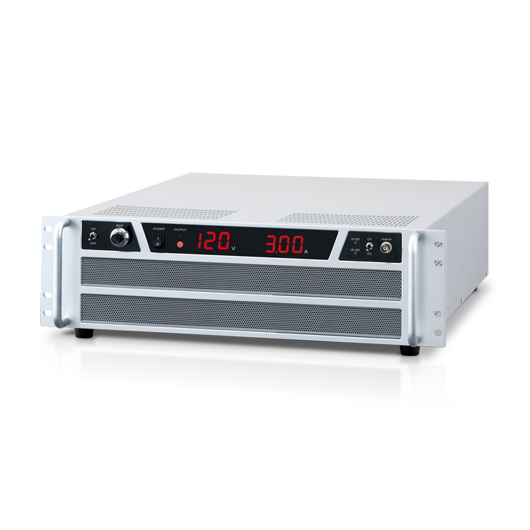
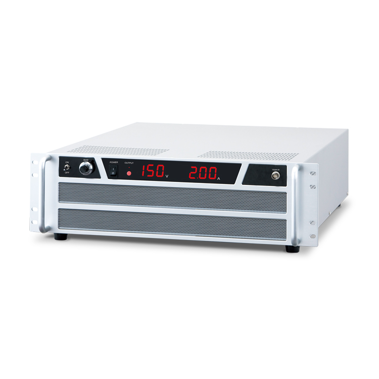
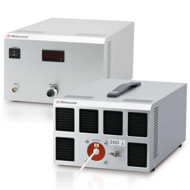
Matsusada Precision as a leading power supply manufacturer introduced direct OUTPUT display
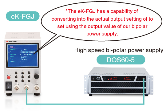
* The picture shows an application example with DOS60-5.
If a different output is used instead of DC, 0 V and 0 A will be displayed since the unit is dedicated to displaying DC output in DOS series
Output value from the function generator can be converted and set based on our bipolar power supplies.
Accordingly, eK-FGJ features the accurate and intuitive setting without calculating with the gain value.
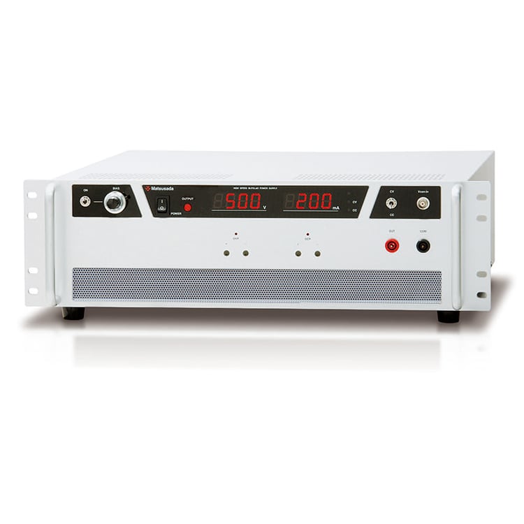
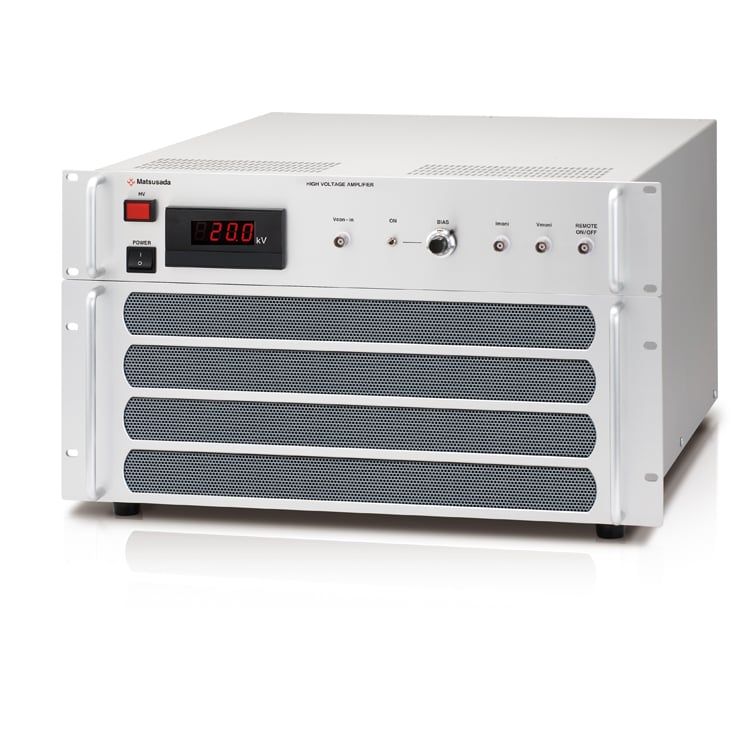
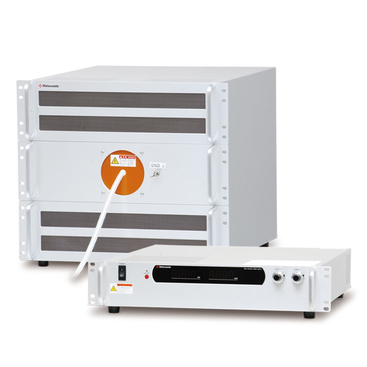
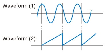
The series offers the synchronous waveform output in two power supplies
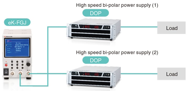
It is possible to apply the opposite synchronous waveform output by positive or negative toward motors or dielectric materials.
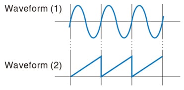
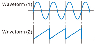
In the series, the synchronous output is available where the two waveforms follow the same patterns in terns of the respective cycle and sweeping start point. Besides, the phase shift is also available where one phase is shifted differing from the other.
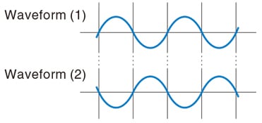
Synchronous Output
It is designed to control the two waveforms by making them the same in terms of the cycles and the sweeping start point.
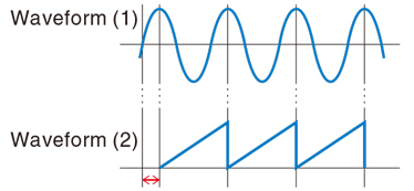
Phase Shift
The output timing is arranged by moving the phase of your choice.
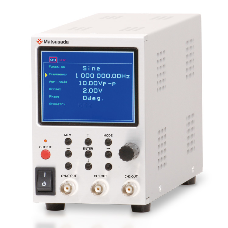
Appearance
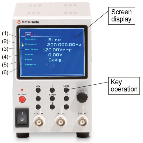
Screen Display
- Function: output waveform selecting (among the waveform items referring to "GENERAL SPECIFICATIONS")
- Frequency: frequency setting/setting value displaying
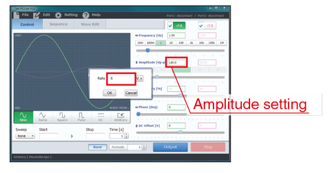
- Amplitude: amplitude setting/setting value displaying
- Offset: DC offsetting/setting value displaying
- Phase: setting of phase to start/setting value displaying
- Symmetry: symmetry setting/setting value displaying (in selecting triangle wave and square wave)
Key Operation
- MEM: memory writing/read screen displaying
- MODE: display switching/setting screen displaying
- ← ↑ ↓ → :cursor movement
- ENTER: to confirm your setting on the memory screen
Specifications
Software
Easy operating exclusive control software as standard equipment
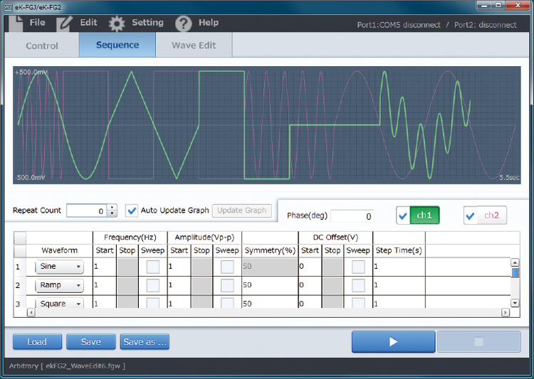
Sequence Programming Screen
Channel 1 (Ch1) and channel 2 (Ch2) can each output signals independently. The output waveform can also be selected as an arbitrary waveform created with dedicated waveform editing software. (Only one arbitrary waveform can be selected at a time for both Ch1 and Ch2.)
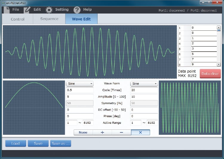
Arbitrary Waveform Generation
Positive and negative outputs are available respectively. You can easily generate various waveforms by adding, subtracting, and multiplying operations.
* Concerning the configuration data used for the output, the reproduction may not always coincide with the actual output waveforms.
The series offers the composition consisting of a sine wave and an amplitude which have different patterns and readily provides the waveform generation.
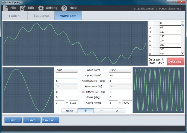
The composition is also available by setting the specified range.
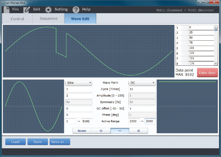
They can be added, subtracted, and multiplied.
Options
Optical Interface Board Option
In selecting this option, the USB board is not included as a standard specification.
- -LGob: Optical interface board + optical cable 2 meters
- -LGob (Fc5): Optical interface board + optical cable 5 meters
- -LGob (Fc10): Optical interface board + optical cable 10 meters
- -LGob (Fc20): Optical interface board + optical cable 20 meters
- -LGob (Fc40): Optical interface board + optical cable 40 meters
Isolation control is performed by optical communication. As complete isolation is performed by means of optical fiber, this enables the prevention of erroneous operation comprising transient phenomena caused by surges, inductive lightning, external noise, etc. (can be produced with the control software).
On the other hand, regarding the communication in this option, before the programming operation is performed or the arbitrary waveform is outputted, it may take several seconds for the power supply to output following the signal output. If you plan to use the unit for such applications, it is not recommended to use this option.
Select the optional optical interface board (-LGob) when using this function generator under the following conditions.
- Noisy environment including factories (Example: Motors or coils are used near power supplies and loads).
- Using with high voltage floating (more than 250 V).
- Installation distance of 2 meters or more between the function generator and a controller such as a computer, laptop, or Programmable Logic Controller (PLC).
How to Order
To order, please add the above option codes to the model number.
- [Sample]
- eK-FGJ-LGob
- eK-FGJ-LGob(Fc5)
Dimensions
Download
If you are unable to download a file
Please try the following solution.
- Please press Ctrl+F5 to clear the cache of your web browser and try again.
- Please restart your web browser and log in again to try again.
- Please change your web browser to another browser and try again.
- Restart the computer and try again.
- Please try again on a different computer.
-
eK-FGJ/eK-FG2 Datasheet
Date: 2023-07-26 rev. 03
PDF (2,555 KB)

-
eK-FGJ Instruction Manual
Date: 2020-09-10 rev0.0
PDF (887 KB)
-
eK-FGJ/eK-FG2 Control Software Instruction Manual
Date: 2020-10-14 rev0.9
PDF (2,158 KB)
-
eK-FGJ/eK-FG2 series USB Driver
Date: 2023-08-23 rev1.7.5
ZIP (6,617 KB)
The account registration is necessary for downloading
-
eK-FGJ/eK-FG2 Datasheet
Date: 2023-07-26 rev. 03
PDF (2,555 KB)
-
eK-FGJ Instruction Manual
Date: 2020-09-10 rev0.0
PDF (887 KB)
-
eK-FGJ/eK-FG2 Control Software Instruction Manual
Date: 2020-10-14 rev0.9
PDF (2,158 KB)
-
eK-FGJ/eK-FG2 series USB Driver
Date: 2023-08-23 rev1.7.5
ZIP (6,617 KB)
In this website, we provide only the latest version of information including instruction manuals as of our products. Therefore, the newest versions of manuals on the website might be not same as the ones of products you purchased in the past.