


Published: ,
Modified: , N.T.
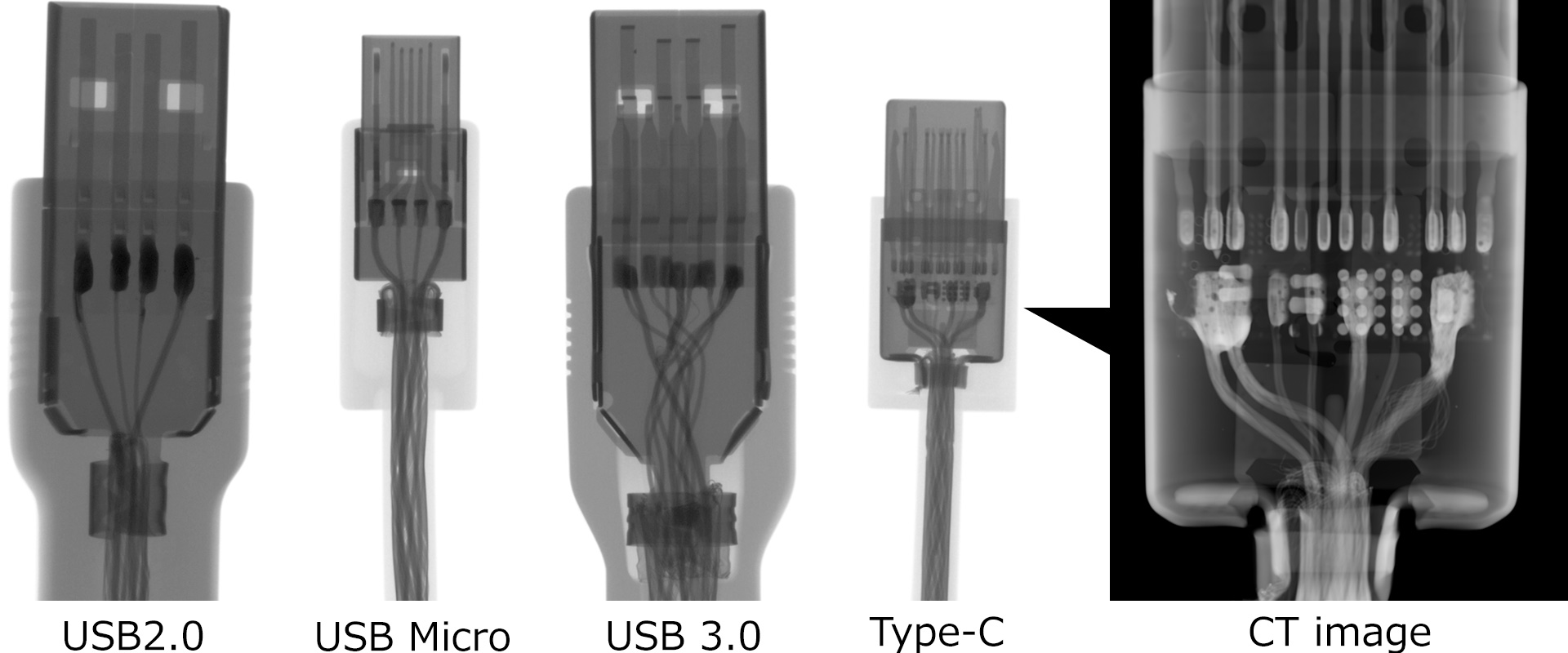
This application note compares X-ray images of four common USB cable connectors: USB 2.0 (Type-A), Micro-USB (Micro-B), USB 3.0 (Type-A), and USB Type-C.
Non-destructive X-ray inspection reveals clear differences in internal structure and wiring density. While standard USB 2.0 and Micro-USB connectors display relatively simple four-line configurations, USB 3.0 and Type-C connectors exhibit significantly higher complexity. Notably, the X-ray image of the Type-C connector clearly reveals an internal printed circuit board (PCB) and fine-pitch connections. These details demonstrate the necessity of high-resolution X-ray systems for verifying soldering quality and internal integrity in modern electronics.
X-ray System Parameters
| Focal spot | Microfocus |
|---|---|
| X-ray tube voltage | 130 kV |
Recommended products

Related Technical Articles
- Selecting an X-ray Inspection System
- Principles of Radiography
- Safe Operation of X-ray Inspection Systems
- What is Microfocus X-ray Technology? (Basic Knowledge)
- Basics and Principles of Computed Tomography (CT)
- Non-Destructive Testing: Types and Applications
- What are X-rays? (Basic Knowledge)
- How to Acquire High-Quality Computed Tomography (CT) Images - X-ray NDT series (1)
- A Guide to X-ray CT Images: Formats, Viewing, and Applications - X-ray NDT series (2)
- X-ray Image Processing and Automated Inspection - X-ray NDT series (3)
- Types of X-ray Tubes and High-voltage Power Supplies
- What is the difference between Radioactivity, Radiation, and Radioactive Materials?
- Understanding Radiation: Effects on the Body and X-ray Safety