


Principles of Non-Destructive Inspection
Most X-ray images are monochromatic. The contrast and grayscale intensity are primarily determined by the amount of X-ray transmission through the object.
X-rays penetrate matter
X-rays are electromagnetic waves with very short wavelengths. Therefore, they can pass between the atoms that make up the substance. However, not all X-rays penetrate an object without being changed. Some X-rays are attenuated as they pass through. A variety of interactions (photoelectric effect, characteristic X-ray emission, inelastic scattering, etc.) occur when X-rays hit the electrons orbiting a nucleus. X-rays that pass through an object without interaction are referred to as transmitted X-rays. On the resulting image, areas with high transmission typically appear brighter (white), while areas where X-rays are attenuated appear darker (black).
Intensity of transmitted X-rays
Generally, the intensity of transmitted X-rays is determined by the following factors.
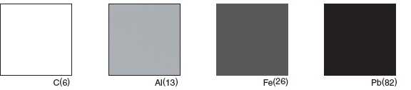
1. More X-rays are blocked as atomic number and density increase.
Changes in X-ray image with different materials of the same thickness
* Atomic numbers are shown in parentheses.
[Image]
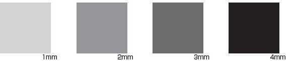
2. More X-rays are blocked as thickness increases.
Changes in X-ray image with the same material in different thicknesses
[Image]
3. X-ray intensity is determined by tube voltage (V) and tube current (A).
Increasing the tube voltage shortens the wavelength of X-rays and makes transmission easier. The value of the tube voltage required for transmission will differ depending on the material of the sample, for example, Al (atomic number 13) or Fe (atomic number 26). Increasing the tube current increases the dose and intensity of X-rays generated, but since the wavelength does not change, objects that are not penetrated are not visible, no matter how much the tube current is increased. Determining the optimal settings for these two conditions (tube voltage and tube current) according to the object you want to see is the key to taking clear X-ray images.
Observation System
The principle of X-ray imaging is similar to shadow projection. The figure below is a schematic diagram of a basic X-ray imaging system.
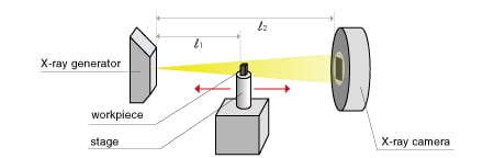
FID: Focus to Image Distance
FOD: Focus to Object Distance
By placing a workpiece between the X-ray generator and the X-ray camera, the X-ray is shielded and a shadow is generated. The shadow is captured by the X-ray camera to generate an X-ray image. The geometric magnification at that time depends on the distance from the X-ray generator to the workpiece (FOD: Focus to Object Distance) [l1] and the distance from the generator to the X-ray camera (FID: Focus to Image Distance) [l2], as shown by the following equation.
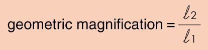
Accordingly, as the workpiece gets closer to the X-ray generator while maintaining the distance of [l2], the geometric magnification becomes higher. In other words, when the workpiece is moved away from the X-ray generator, the geometric magnification becomes lower, which is suitable for the wide-field observation images.
Observation example 1: Structural analysis of products, detection of foreign material
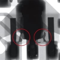
Short circuit caused by bad soldering
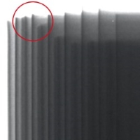
Alignment gap in rechargeable battery electrode winding
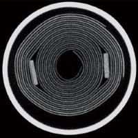
CT analysis of a capacitor
Observation example 2: Detection of voids (blowholes/air layers) in structures
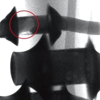
Solder blow holes
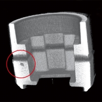
CT analysis of blowholes in a die-casting
Related Technical Articles
Recommended products
Matsusada Precision manufactures and sells X-ray non-destructive inspection systems, X-ray CT scanners, X-ray modules, high-voltage power supplies for X-ray tubes.


