


Principle of X-ray CT
In this section, we explain the principles of X-ray CT and the key differences between medical and industrial systems. "CT" stands for "Computed Tomography." It is a non-destructive testing method used to visualize the internal structure and material composition of an object by detecting transmitted radiation. X-ray CT specifically utilizes X-rays as the source. While medical CT scans are widely recognized, the technology is also essential for industrial applications.
Medical CT often uses a contrast medium injected into the bloodstream to image vessels and tissues. The contrast agent absorbs X-rays, appearing darker or lighter on the detector relative to surrounding tissues, allowing doctors to identify blood vessels and abnormalities.
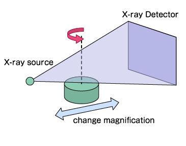
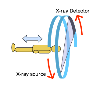
Industrial CT, however, is designed to inspect inanimate objects without disassembly. A major structural difference exists between the two: in industrial CT, the X-ray source and detector remain stationary while the sample is placed on a rotating stage to capture images from 360 degrees. Magnification is adjusted by changing the distance between the sample and the X-ray source (FOD/FDD). Conversely, medical CT systems rotate the X-ray source and detector around the patient, who remains stationary..
Industrial CT
Medical CT
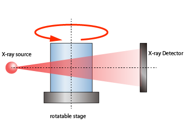
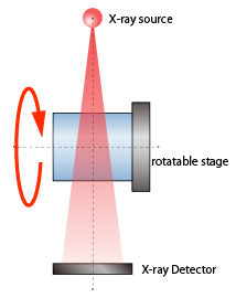
Industrial CT systems are generally categorized into horizontal and vertical configurations. In horizontal systems, the X-ray source, rotating stage, and detector are aligned horizontally. Vertical systems align these components vertically.
While both configurations offer similar imaging capabilities, vertical systems occupy less floor space. However, horizontal systems are better suited for large or heavy samples, as securing heavy objects on a vertical rotation stage can be challenging. Selection depends on the sample's size, weight, and shape.
Since the 1990s, resolution has improved significantly with the adoption of microfocus X-ray sources. In the X-ray generator, an electron beam from the cathode is focused by electromagnetic lenses and strikes the anode (target) to generate X-rays. The specific point of impact is called the "X-ray focal spot."
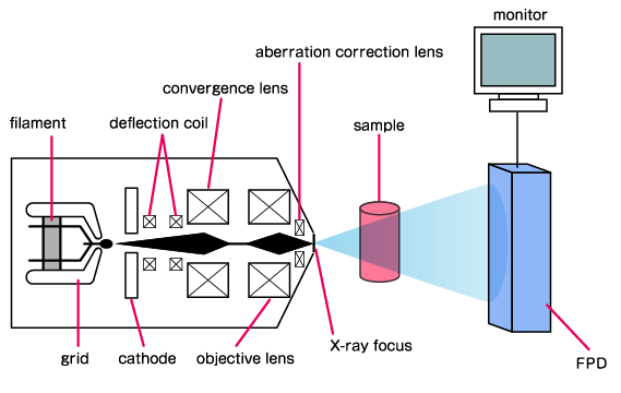
The size of the focal spot directly affects image sharpness. A larger focal spot causes X-rays to enter the detector from slightly different angles, creating a penumbra effect known as "blur" or geometric unsharpness. Minimizing the focal spot size reduces this blur, resulting in sharper images.
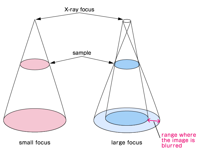
Geometric magnification increases as the sample moves closer to the X-ray source. However, without a small focal spot, high magnification will simply result in a blurred image. Therefore, a microfocus X-ray source is essential for inspecting fine structures at high magnification.
Reducing the focal spot size allows for higher resolution even at standard magnifications. However, concentrating the electron beam into a smaller area increases the heat density on the target, potentially damaging the anode. To prevent this, the X-ray power (current) must be limited.
Lowering the power reduces image brightness and affects the Signal-to-Noise (S/N) ratio. Therefore, achieving optimal high-resolution images requires balancing focal spot size with the necessary S/N ratio.
Handling and Precautions of X-ray CT Scanning Mode
Several factors can introduce errors or noise during X-ray CT scanning. Key factors include:
- X-ray source stability
- Geometric alignment
- Mechanical precision (Stage movement)
- Detector characteristics
- Sample properties
- Scan parameters
- Environmental conditions
- Data processing algorithms
First, thermal stability of the X-ray source is critical. Ambient temperature changes can cause "temperature drift," shifting the focal spot position. This drift leads to axis misalignment and image blurring, resulting in poor contrast or inaccurate dimensional measurements. Minimizing drift requires a stable environment and warm-up operation.
This causes such problems as poor contrast in the contours of CT images and inaccurate material density.
Geometric errors occur if the mechanical alignment of the source, stage, and detector deviates from the ideal geometry. Similarly, mechanical errors, such as stage wobble (eccentricity), can compromise the accuracy of the reconstructed 3D model.
Detector calibration is also vital. Uncorrected sensitivity differences between pixels (gain/offset) can cause ring artifacts. Regular calibration (gain/offset correction) is necessary to ensure consistent image quality.
Sample properties also cause artifacts. High-density materials, such as metals, absorb lower-energy X-rays preferentially--a phenomenon known as "beam hardening." This often results in "metal artifacts" (dark streaks or starburst patterns) when metals are present in lower-density materials. Beam hardening correction software can mitigate this.
"Ring artifacts" appear as concentric circles when specific detector pixels have inconsistent output. "Streak artifacts" can occur due to scattering or insufficient penetration in certain directions.
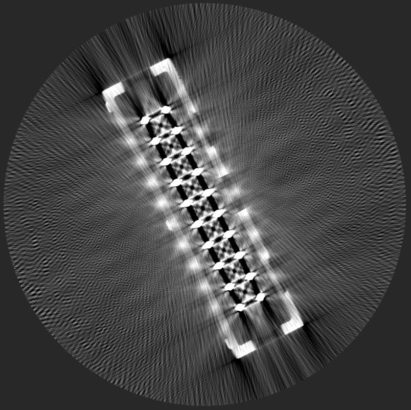
metal artifact
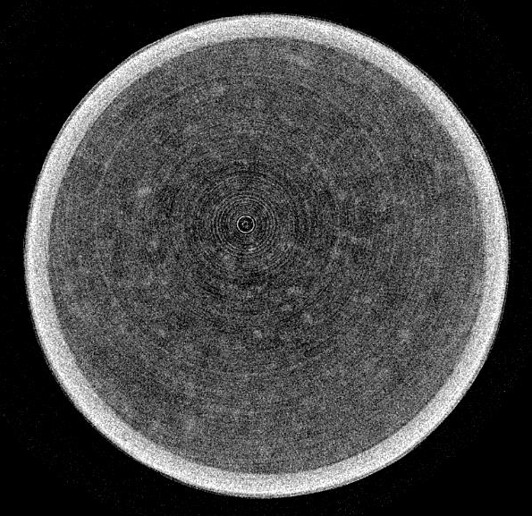
ring artifact
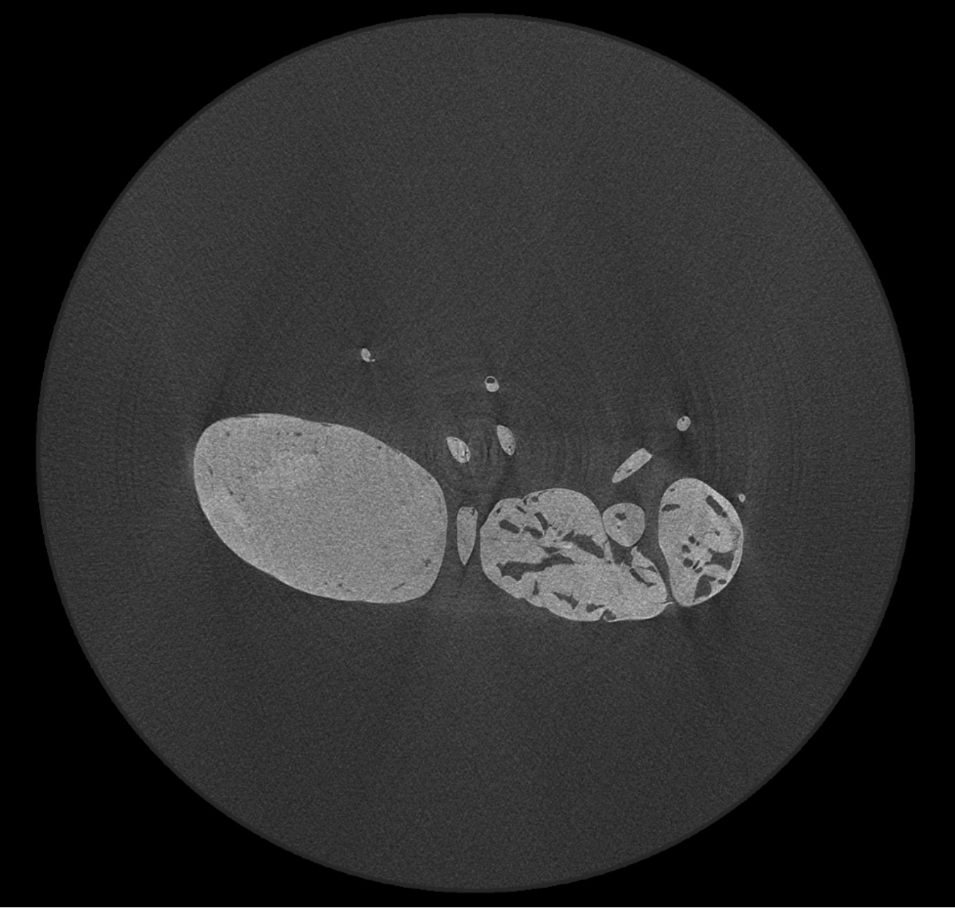
shower-like artifact
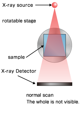
Different scanning modes are used to reduce errors and accommodate larger samples. "Normal Scan" (or Center Scan) aligns the X-ray source, sample center, and detector center in a straight line.
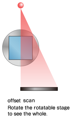
However, standard detectors have a limited field of view (FOV). To image samples larger than the detector width, "Offset Scan" is used. In this mode, the rotation center is shifted sideways relative to the optical axis, effectively doubling the scan width during reconstruction. Accurate image synthesis in offset scanning requires precise axis correction.
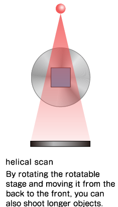
Additionally, "Helical Scan" is used for long objects. This method moves the sample vertically while rotating it, capturing a spiral path of data. This allows for the inspection of tall samples that exceed the detector's vertical height in a single continuous scan.
In the next article, we will discuss "A Guide to X-ray CT Images: Formats, Viewing, and Applications - X-ray NDT series (2).
Related Technical Articles
Recommended products
Matsusada Precision's X-ray CT Scanners can take high-definition and High-resolution images with its unique microfocus X-ray technology.


Reference (Japanese site)
- Japanese source page 「X線非破壊検査シリーズ① X線CT画像をきれいに撮影するには?」
(https://www.matsusada.co.jp/column/xxct1.html) - X線CT画像の高精度化と画像情報に基づく非破壊検査技術【産技助成Vol.11】
(新エネルギー・産業技術総合開発機構)
https://www.nedo.go.jp/news/press/AA5_0383A.html - X線CTとは(物質・材料研究機構)
(https://www.nims.go.jp/personal/XrayCT/index.html) - CTの基礎(CT適塾)
(https://www.ct-tekijyuku.net/basic/) - マイクロフォーカスX線CTの撮像原理と解析例
(https://www.jstage.jst.go.jp/article/sfj/66/12/66_594/_pdf) - 「日本非破壊検査協会「ラジオグラフィを支えるマイクロフォーカスX線」特集号刊行にあたって
(https://www.jsndi.jp/bulletin/J_01_Jun09.html) - 計測用X線CTの高精度化に関する調査研究
(https://www.jstage.jst.go.jp/article/sicejl/56/9/56_709/_pdf) - アーチファクトに注意しよう【CTスキャン解説④】
(https://white-rabbit.jp/artifact/)