


The software for CT scanners features advanced image processing and analysis functions to generate high-resolution 3D images.
Benefits of X-ray CT system
- Observation from multiple directions
- Non-contact measurement
- Distance measurement
- Volume measurement
- Rendering object properties
- Utilized for reverse engineering
- Contributing to product development
(speedy visualization of defects)
Computed Tomography Basics
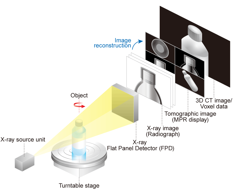
Computed Tomography (CT) is an advanced non-destructive testing (NDT) technology that utilizes computer processing to generate precise cross-sectional images of an object from a series of 2D X-ray projections. During an industrial CT scan (also known as micro-CT), the object is precisely rotated while hundreds or thousands of 2D X-ray images are acquired from various angles.
This type of imaging is called a cone-beam CT scan. Sophisticated reconstruction software then processes this series of projection images to generate a stack of cross-sectional slices (tomographic images). By compiling these slices, a complete three-dimensional (3D) volume model, composed of volumetric pixels (voxels), is created.
Normal scan vs Offset scan
In cone-beam CT normal scan, if the width of the vision image of the sample is larger than the width of the X-ray camera, you need to shoot the sample repeatedly to obtain the tomographs. The offset scan technique overcomes this limitation. By shifting the detector horizontally relative to the center of rotation, it's possible to scan objects up to nearly twice the width of the detector in a single rotation, significantly expanding the effective scanning volume and improving workflow efficiency.


Models
| Function | -CTN | -CTDa | -CTM | -CTDaX | ||
|---|---|---|---|---|---|---|
| Scan mode | Normal scan | |||||
| Half scan | ||||||
| Offset scan | ||||||
| Reconstruction | Noise suppresion | |||||
| Metal artifact reduction | - | - | ||||
| Beam hardening reduction | - | - | ||||
| Ring artifact reduction | - | - | ||||
| Simple analysis | 2D | 2D cross-section surface display | ||||
| MPR image display | ||||||
| 3D | 3D tomographic image | - | ||||
| Volume rendering | - | |||||
| Measurement | Dimension (distance) measurement | |||||
| Angle measurement | - | - | ||||
| 2D/3D internal diameter measurement | - | - | ||||
| 3D fitting | - | - | ||||
| 3D particle analysis | - | - | ||||
| 3D drawing | - | - | ||||
| Saving in DICOM format | - | - | ||||
| 3D CT Image analysis software |
ROI visualization | Visualization | - | |||
| Creating and editing of ROI | - | - | ||||
| Volume/Surface area measurement | - | - | ||||
| Standard functions | Gray-scale value analysis | - | - | - | ||
| Data quality analysis | - | - | - | |||
| Arbitrary object separation | - | - | - | |||
| Import | STL | - | ||||
| Point cloud | - | - | - | |||
| CT scan image | - | |||||
| VGL | - | |||||
| VGARCHIVE | - | - | ||||
| MVGL | - | - | ||||
| STEP/IGES (standard function) | - | - | - | |||
| Integrated mesh | - | - | - | |||
| Export | Saved images | |||||
| 2D tomograhic movie | - | |||||
| Analysis report | - | - | ||||
| Images (of raw, ImageStack, etc.) | - | - | ||||
| Q-DAS file | - | - | ||||
| CAD (.stp) 3D movie | - | - | - | |||
| 3D movie | - | |||||
| Convert and Export | STL conversion | - | - | - | ||
| Surface mesh (STL) conversion | - | - | - | |||
| Volume mesh (tetrahedron) | - | - | - | |||
| Reverse engineering (CAD conversion) | - | - | - | |||
| Others | CAE collaboration | - | - | - | ||
| Merging filters/ images |
Advanced image merging | - | - | - | ||
| Gauss/Application gauss | - | - | - | |||
| Median | - | - | - | |||
| FIB/SEM correction | - | - | - | |||
*precision CT9600 has the -CTDa feature as standard, and selectable -CTDaX as an option.
RECONSTRUCTION
The image reconstruction process involves a computer generating cross-sectional images from the projection data collected by the CT scanner. This results in false and unwanted features in the image, called artifacts, which can be mitigated by software options.
Ring Artifact Reduction
Ring artifact reduction reduces concentric ring noise that occurs in tomographic images through a filtering process.
- -CTN
- -CTDa
- -CTM
- -CTDaX


Advanced Metal Artifact Reduction
This powerful function significantly reduces streak and flare artifacts caused by high-density materials. It provides cleaner, more reliable data for accurate structural analysis and internal inspection, even on complex multi-material assemblies.
- -CTN
- -CTDa
- -CTM
- -CTDaX


2D IMAGE

Here is an observation example of a capacitor (size approximately 0.24 inches (6 mm) in diameter, 0.39 inches (10 mm) in height.
- -CTN
- -CTDa
- -CTM
- -CTDaX
Arbitrary Tomographic Images
Displays tomographic images at arbitrary position.

Multi Planar Reconstructions (MPR)
Displays tomographic images of the 3D volume data from three directions.

3D IMAGE
- -CTN
- -CTDa
- -CTM
- -CTDaX
3D Arbitrary Tomographic Images
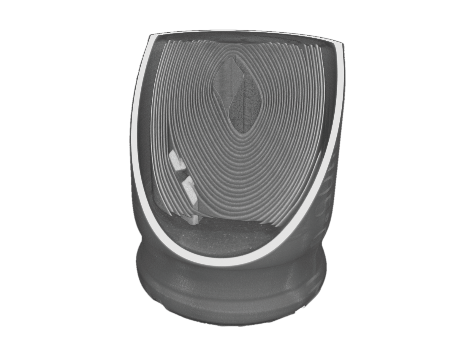
Visualizes volume-rendered 3D tomographic images.

Volume Rendering
Displays images that are generated from voxel data with all XYZ information. By changing the viewpoint, images from all directions can be displayed.

ANALYSIS FUNCTION
Dimension Measurement
Measures dimensions between specified points on a 2D image. The measurement results are reflected in a 3D image. (-CTN option is only 2D images.)
- -CTN
- -CTDa
- -CTM
- -CTDaX


Shortest Distance Measurement
Measures the shortest (or longest) distance on a 2D image. The distance is automatically measured by dragging the mouse, displaying the dimensions of the specific parts. The measurement results are reflected in the 3D image.
- -CTN
- -CTDa
- -CTM
- -CTDaX


Volume/Surface Area Measurement
Measures the volume or surface area of a read 3D image.
- -CTN
- -CTDa
- -CTM
- -CTDaX

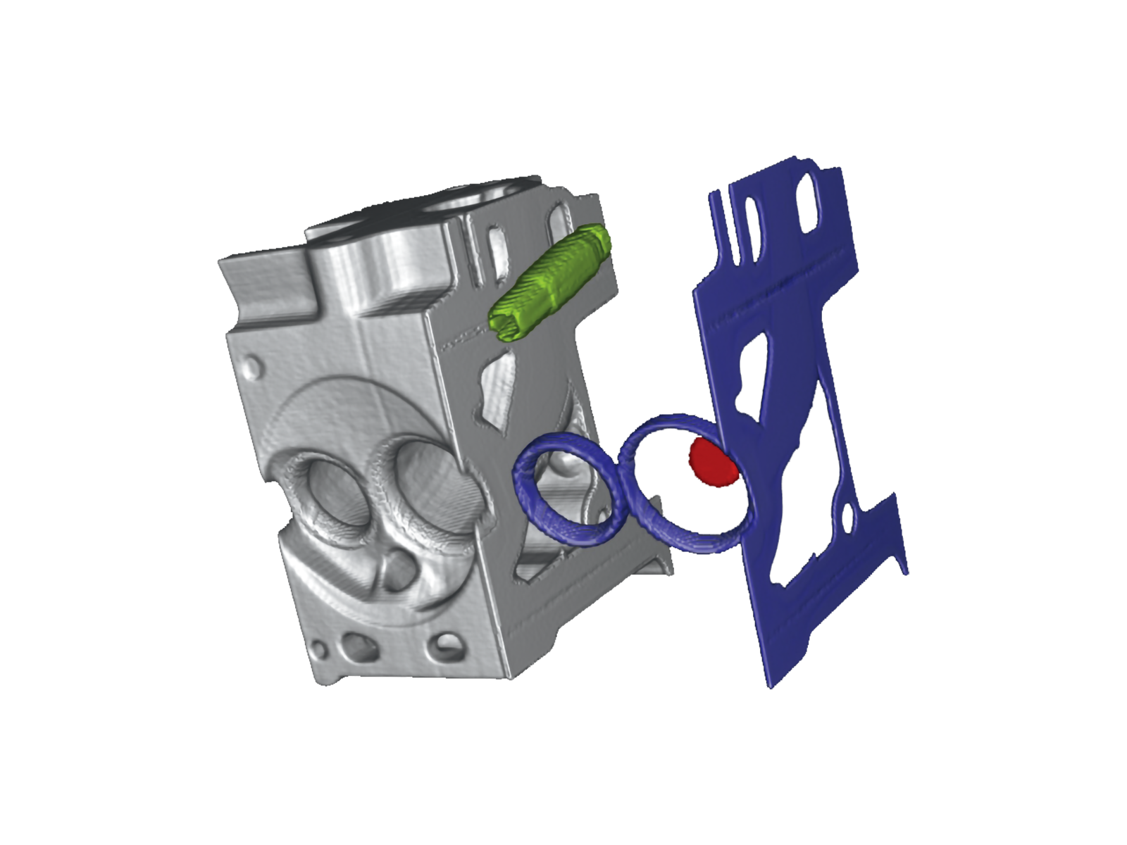
Arbitrary Object Separation
Arbitrarily extracts some part of an image to color or separate it.
- -CTN
- -CTDa
- -CTM
- -CTDaX

CAD Data Export
CAD data can be output in the STL file format, which represents the surface geometry of a 3D model as triangular polygons.
- -CTN
- -CTDa
- -CTM
- -CTDaX

Additional Analytical Functions (*-CTDax option required)
- -CTN
- -CTDa
- -CTM
- -CTDaX
| Reconstruction and quality analysis of image data |
|
|---|---|
| Surface determination |
|
| CAD import |
|
| GD&T |
|
| Reverse engineering |
|
| Material analysis |
|
| Volume mesh and simulation |
|
Geometric Dimensioning and Tolerancing (GD&T)
Using 3D analysis data, you can inspect internal structures, foreign matter, or shrinkage cavities in castings that cannot be measured by contact-type instruments. It is suited for mold designs and inspections of shrinkage cavities in casting.
Nominal/Actual Comparison (Part-to-CAD)
Directly compare your scanned data (as-built) against the original CAD model (as-designed). This generates an intuitive, color-coded deviation map, instantly highlighting any manufacturing errors or warping with precision. Different colors can identify deviations.


Wall thickness analysis
Visualizes wall thickness by comparing CAD data with CT scan data. It also highlights deviations from design values, allowing errors to be easily identified by color mapping.

Wall thickness analysis (2D-display)
Three-dimensional images are used for the wall thickness measurement.

Material Analysis
Automated Defect & Porosity Analysis
Automatically detect, locate, and quantify the size, volume, and distribution of internal defects such as pores, voids, and inclusions. This is crucial for quality assurance in castings, additive manufacturing (AM), and composite materials. It can also calculate the percentage of defects to the sample volume. It is available in the following categories.
- Scale (circumscribed sphere)/Volume
- Surface area
- Position XYZ
- Self - Sphericity
- Spacing (distance between defects)
- Projected size XYZ


Datasheets
If you are unable to download a file
Please try the following solution.
- Please press Ctrl+F5 to clear the cache of your web browser and try again.
- Please restart your web browser and log in again to try again.
- Please change your web browser to another browser and try again.
- Restart the computer and try again.
- Please try again on a different computer.
Login Required
-
Micro View X-Ray CT System Guide
Date: 2025-09-12 Rev 08
PDF (4,989 KB)
Related Technical Articles
Similar products
-
New
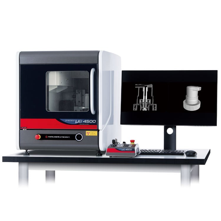
precision µB4500
- X-ray tube voltage
- 90 kV
- X-ray power
- 13.5 W
Benchtop X-ray CT Scanner -
New
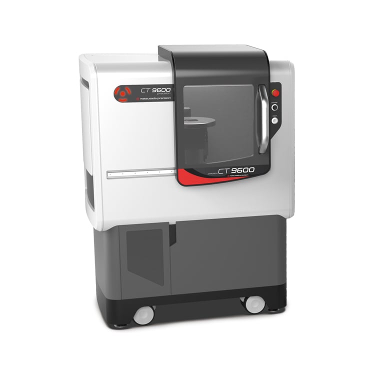
precision CT9600
- X-ray tube voltage
- 130 kV
- X-ray power
- 40 W
Industrial Micro-CT Scanner -
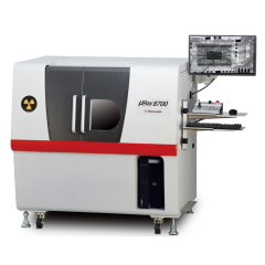
µRay8700/µRay8760
- X-ray Tube Voltage
- 130 kV
- X-ray Power
- 40 W
X-ray Inspection System with Optional CT FunctionHigh-Penetration X-ray Inspection System
-
New
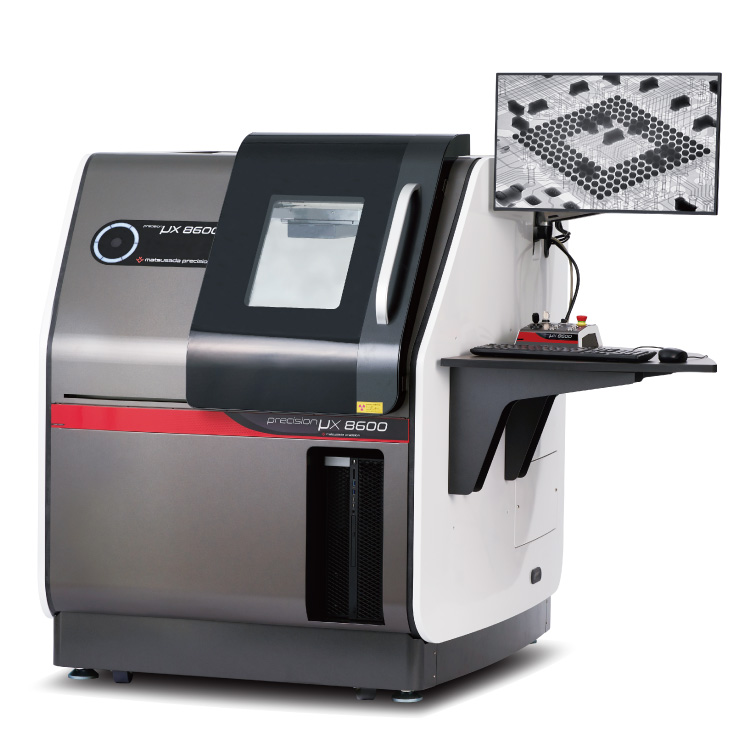
precision μX8600
- X-ray tube voltage
- 130 kV
- X-ray power
- 40 W
Microfocus X-Ray Inspection SystemOptimized for Large Samples and PCBs
Product Lineup:
X-ray Inspection SystemsUser Support
FAQ
- What is Micro‑focus X‑ray?
- What is the tube voltage for X‑ray inspection systems?
- Is a license required for usage of X‑ray inspection system?
- What is the difference between medical and industrial CT scans?
- What is the difference between an X‑ray inspection system and a CT scan system?
- How do we reduce concentric circle noise (ring artifact) in CT images?