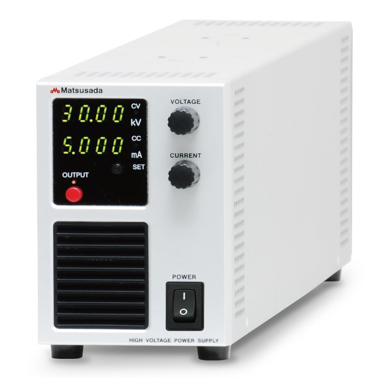
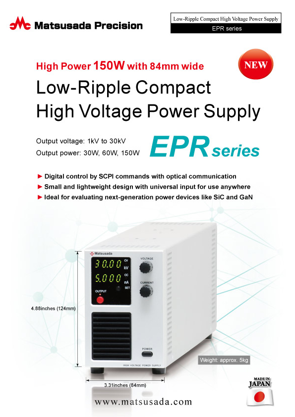
LOW-RIPPLE COMPACT
HIGH VOLTAGE POWER SUPPLY
- Output voltage:
1kV to 30 kV - Output power:
30 W, 60 W, 150 W - Width only 3.31-inch
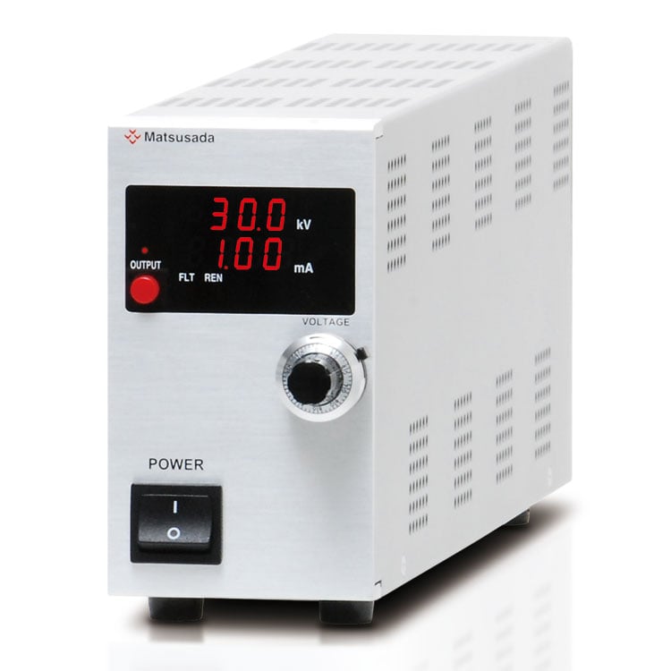
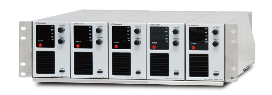
Compact Design: 150 W Output in a Lightweight 84 mm Profile
The EPR series is a line of compact, high-power, high-voltage power supplies delivering up to 30 kV and 150 W from a slim 84 mm wide form factor. For enhanced reliability in noisy environments, optional fiber optic interfaces provide complete electrical isolation for digital control, including via SCPI commands. The EPR series is ideal for a wide range of applications, from cutting-edge research and development of next-generation power devices such as SiC and GaN, as well as for educational and laboratory applications.
FEATURES AND BENEFITS
- Universal AC Input: Operates on any AC input from 100 V to 240 V for worldwide compatibility.
- Versatile Digital Control: A wide variety of digital interfaces, including USB, LAN, RS-232C, RS-485, and GPIB, are available through optional optical interface adapters.
- Compact Powerhouse: Delivers high voltage and high power from a remarkably small and lightweight package, weighing only approximately 5 kg.
- Ideal for evaluating next-generation power devices like SiC and GaN
APPLICATIONS
- Next-Generation Power Device Testing: Ideal for the evaluation and testing of SiC, GaN, and other wide-bandgap semiconductor devices.
- Component Testing: Perfectly suited for capacitor charging tests, insulation testing, and breakdown voltage tests.
- R&D and System Integration: A reliable high-voltage source for applications including electron beam, ion beam, automatic test equipment (ATE), and X-ray systems.
- General Purpose High Voltage Source: Its compact size and ease of use make it a convenient benchtop tool for all types of high-voltage experiments and aging tests.
Models
| Model | Maximum Output | ||
|---|---|---|---|
| Voltage | Current | Power | |
| EPR-1P30 | 1 kV | 30 mA | 30 W |
| EPR-1P60 | 60 mA | 60 W | |
| EPR-1P150 | 150 mA | 150 W | |
| EPR-1.5P20 | 1.5 kV | 20 mA | 30 W |
| EPR-1.5P40 | 40 mA | 60 W | |
| EPR-1.5P100 | 100 mA | 150 W | |
| EPR-2P15 | 2 kV | 15 mA | 30 W |
| EPR-2P30 | 30 mA | 60 W | |
| EPR-2P75 | 75 mA | 150 W | |
| EPR-3P10 | 3 kV | 10 mA | 30 W |
| EPR-3P20 | 20 mA | 60 W | |
| EPR-3P50 | 50 mA | 150 W | |
| EPR-5P6 | 5 kV | 6 mA | 30 W |
| EPR-5P12 | 12 mA | 60 W | |
| EPR-5P30 | 30 mA | 150 W | |
| EPR-10P3 | 10 kV | 3 mA | 30 W |
| EPR-10P6 | 6 mA | 60 W | |
| EPR-10P15 | 15 mA | 150 W | |
| EPR-15P2 | 15 kV | 2 mA | 30 W |
| EPR-15P4 | 4 mA | 60 W | |
| EPR-15P10 | 10 mA | 150 W | |
| EPR-20P1.5 | 20 kV | 1.5 mA | 30 W |
| EPR-20P3 | 3 mA | 60 W | |
| EPR-20P7.5 | 7.5 mA | 150 W | |
| EPR-30P1 | 30 kV | 1 mA | 30 W |
| EPR-30P2 | 2 mA | 60 W | |
| EPR-30P5 | 5 mA | 150 W | |
| Model | Maximum Output | ||
|---|---|---|---|
| Voltage | Current | Power | |
| EPR-1N30 | -1 kV | 30 mA | 30 W |
| EPR-1N60 | 60 mA | 60 W | |
| EPR-1N150 | 150 mA | 150 W | |
| EPR-1.5N20 | -1.5 kV | 20 mA | 30 W |
| EPR-1.5N40 | 40 mA | 60 W | |
| EPR-1.5N100 | 100 mA | 150 W | |
| EPR-2N15 | -2 kV | 15 mA | 30 W |
| EPR-2N30 | 30 mA | 60 W | |
| EPR-2N75 | 75 mA | 150 W | |
| EPR-3N10 | -3 kV | 10 mA | 30 W |
| EPR-3N20 | 20 mA | 60 W | |
| EPR-3N50 | 50 mA | 150 W | |
| EPR-5N6 | -5 kV | 6 mA | 30 W |
| EPR-5N12 | 12 mA | 60 W | |
| EPR-5N30 | 30 mA | 150 W | |
| EPR-10N3 | -10 kV | 3 mA | 30 W |
| EPR-10N6 | 6 mA | 60 W | |
| EPR-10N15 | 15 mA | 150 W | |
| EPR-15N2 | -15 kV | 2 mA | 30 W |
| EPR-15N4 | 4 mA | 60 W | |
| EPR-15N10 | 10 mA | 150 W | |
| EPR-20N1.5 | -20 kV | 1.5 mA | 30 W |
| EPR-20N3 | 3 mA | 60 W | |
| EPR-20N7.5 | 7.5 mA | 150 W | |
| EPR-30N1 | -30 kV | 1 mA | 30 W |
| EPR-30N2 | 2 mA | 60 W | |
| EPR-30N5 | 5 mA | 150 W | |
To order specifications other than those listed in this datasheet, contact our sales staff for more information.
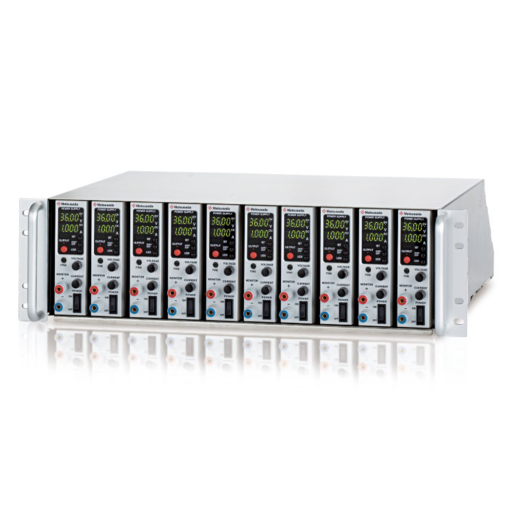
EPR series can be easily installed up to five units with RMO series, rack mount shelf (sold separately, Model No. RMO-133H-EPR).
Functions
Remote Control Connector (Control)
D-Sub 15-pin female (mating connector enclosed).
Remote/Local change

| Output | External relay | Open collector |
|---|---|---|
| Remote | Short | VCE ≤ 0.4 V |
| Local | Open | VCE ≥ 2 V |
Sink Current ≥ 10 mA
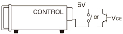
External output ON/OFF
| Output | External relay | Open collector |
|---|---|---|
| ON | Short | VCE ≤ 0.4 V |
| OFF | Open | VCE ≥ 2 V |
Sink Current ≥ 10 mA
- When Safe Start (AC Power-Fail Protection) is ON: High voltage output is enabled only when both the OUTPUT switch and the external ON/OFF signal are active. The unit resets to OFF after a power failure.
- When Safe Start is OFF: High voltage output resumes automatically if the external ON/OFF signal is active (during remote control).
Output Control remote analog programming
| Output voltage | Vcon |
|---|---|
| 0 to Maximum | 0 to 10 V Input impedance ≥ 1 MΩ |
| Output current | Icon |
|---|---|
| 0 to Maximum | 0 to 10 V Input impedance ≥ 1 MΩ |
Output monitor

The monitor output is 0 to +10 V for 0 to Max. Output impedance 1 kΩ
Interlock
Output Enable: The high voltage output is enabled when the interlock circuit is closed (shorted) or when an open-collector TTL signal is low (VCE ≤0.4 V).
Output Disable: The output is immediately disabled if the interlock circuit is opened or the TTL signal is high (VCE ≥2 V).
Reset Procedure: After an interlock trip, the interlock circuit must be returned to the 'Enable' state. The power supply must then be reset by cycling the main power switch (OFF, then ON) to resume operation.
Sink current ≥ 10 mA
Specifications
- Input voltage
- 85 to 264 Vac, 50/60 Hz, Single-phase
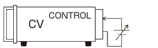
- Output voltage control
-
[Local] Rotary encoder on front panel
[Analog remote] External control voltage 0 to 10 Vdc
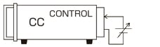
[Digital remote] Command (option) - Output current control
-
[Local] Rotary encoder on front panel
[Analog remote] External control voltage 0 to 10 Vdc
[Digital remote] Command (option)
For details, download the datasheet below.
Notice of POWER switch changes
We inform you that the power switch on the front panel has been changed as shown in the diagram below.
| Before | After |
|---|---|
Push button switch 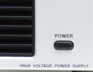 |
Rocker switch 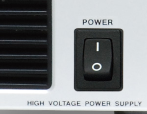 |
Options
- -LDe
-
Pulse/Ramp Sequence
The following output control modes (A to C) are available:A. Pulse (Step) Sequence Function
The Sequence function lets you generate complex voltage and current patterns by automatically cycling through settings stored in memories a, b, and c. You can run the sequence continuously or for a specified number of cycles. By setting the duration of any step (a, b, c, or off) to 0.0, you can easily skip steps to create custom test patterns. This flexibility is ideal for product evaluation and reliability testing.
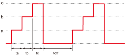
The parameters ta, tb, tc, and toff can be set from 0.0 s to 9999 h 59 m 59.9 s.
B. Ramp Function
The Ramp function provides linear control to gradually increase the output to a set voltage/current, or decrease it to zero. This feature is useful for applications that require a slow power-up or power-down.
*The ramp operation can be applied to: Voltage and Current, Voltage Only, or Current Only.
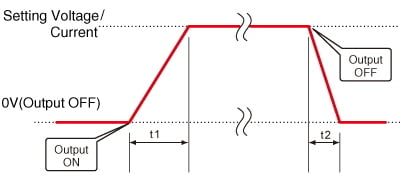
The t1 and t2 parameters can be set from 0.0 s to 9999 h 59 m 59.9 s.
C. Combined Sequence and Ramp
For advanced control, the sequence and ramp functions can be used together. It can create complex profiles by smoothly ramping voltage or current between up to 20 defined discrete steps of memory a, b, c to t. The entire waveform can be run continuously or for a preset number of cycles, making it powerful in a variety of test scenarios.
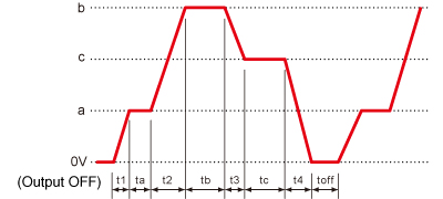
t1 to t4, ta to tt and toff can be set from 0.0 s to 9999 h 59 m 59.9 s.
- -LGob
-
Optical interface port
This option changes the standard interfaces to built-in optical interface port. By combining this option with an adapter for optical connection (sold separately), communication between the control device and the power supply can be controlled in an isolated state. Be sure to select this option when using the product in the following environments.- -LGob: Optical interface port + optical cable 2 meters
- -LGob(Fc5): Optical interface port + optical cable 5 meters
- -LGob(Fc10): Optical interface port + optical cable 10 meters
- -LGob(Fc20): Optical interface port + optical cable 20 meters
- -LGob(Fc40): Optical interface port + optical cable 40 meters
Select the optional optical interface port (-LGob) when using this DC power supply under the following conditions.
- Electrically noisy environments, such as factories with motors, coils, or inverters operating nearby.
- If this power supply and your controller (PC or PLC) cannot be installed within 2 meters.
- When there is a possibility of arcing or output short-circuit.
- -LZ
-
Handle
The handle for carrying will be equipped. (Height will increase by 8 mm.)
- -L(5m)
-
Change of high voltage output cable length
Change the length of the High Voltage output unshielded cable to 5-meter.
How to Order
When ordering, add Option No. to Model No.
Example: EPR-1P60-LGob(Fc5)Z(5m)
Accessories
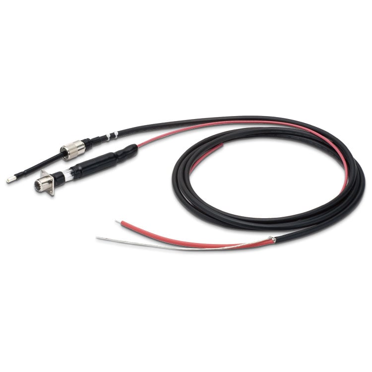
- Optical isolation adapter
-
To use the optical interface, you need to prepare an optical interface adapter separately. The following interface adapters are available according to your controller port.
- CO-E32: LAN to optical interface adapter
- USB-OPT: USB to optical interface adapter
- CO-OPT2-9: RS-232C (9 pin) to optical interface adapter
- CO-OPT2-25: RS-232C (25 pin) to optical interface adapter
- CO-OPT4-25: RS-485 (25 pin) to optical interface adapter
- CO-G32: GPIB to optical interface adapter (Scheduled for discontinuation in December 2028)
Example of communication with optical fiber 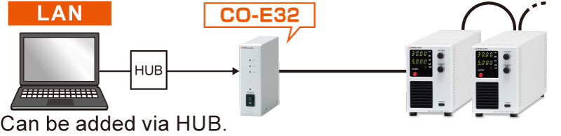
For details, refer to CO/USB series
- Input Cable
-
Included accessory CABLE TYPE1 

125 V / 10 A 2.5 meters
Fixed lengthAdditional accessory
(For the input of 200 V)CABLE TYPE3 
250 V / 10 A 2.5 meters
Fixed lengthAdditional accessory
(For the input of 200 V)CABLE TYPE4 
250 V / 10 A 2.5 meters
Fixed length
- Output cable
-
OUTPUT CABLE Included accessory 40kV CN-40-AHVP 
1.5 meters Included accessory
(with -L(5m) option)40kV CN-40-AHVP(5) 5 meters
- Application software
-
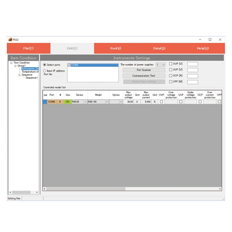
PSS2en series: Remote control, Test workflow design, and Data logging
Click here for the PSS2en seriesPSS2en is the dedicated software that can actuate various power supplies, electronic loads, and digital controllers for power supplies manufactured by Matsusada Precision Inc. with a simple setup.
It is perfect for the aging test, the burn-in test, and the withstand voltage test for electronic parts, as well as for the endurance test, intermittent/continuous operation test, or various simulation tests for automobile electric components.

Download
If you are unable to download a file
Please try the following solution.
- Please press Ctrl+F5 to clear the cache of your web browser and try again.
- Please restart your web browser and log in again to try again.
- Please change your web browser to another browser and try again.
- Restart the computer and try again.
- Please try again on a different computer.
-
EPR series Datasheet
Date: 2026-01-26 rev 14
PDF (1,820 KB)
-
Safety and Usage of High voltage Power supply
Date: 2025-09-08 rev 04
PDF (602 KB)
-
High Performance High Voltage Power Supplies
Date: 2026-02-09 rev 13
PDF (4,555 KB)

-
EPR series Instruction Manual
Date: 2026-03-06 rev 0.4
PDF (682 KB)
-
EPR series Instruction Manual (LDe option)
Last updated: December 18, 2019 rev.0.0
PDF (834 KB)
-
EPR series Instruction Manual (LGob option)
Date: 2023-11-18 rev 0.6
PDF (761 KB)

-
EPR series Outline Drawing (DXF, PDF)
Date: 2024-07-31
ZIP (696 KB)
Login Required
-
EPR series Datasheet
Date: 2026-01-26 rev 14
PDF (1,820 KB)
-
Safety and Usage of High voltage Power supply
Date: 2025-09-08 rev 04
PDF (602 KB)
-
High Performance High Voltage Power Supplies
Date: 2026-02-09 rev 13
PDF (4,555 KB)
-
EPR series Instruction Manual
Date: 2026-03-06 rev 0.4
PDF (682 KB)
-
EPR series Instruction Manual (LDe option)
Last updated: December 18, 2019 rev.0.0
PDF (834 KB)
-
EPR series Instruction Manual (LGob option)
Date: 2023-11-18 rev 0.6
PDF (761 KB)
-
EPR series Outline Drawing (DXF, PDF)
Date: 2024-07-31
ZIP (696 KB)
On this website, we provide only the latest versions of information and instruction manuals for our products. Therefore, the newest versions of manuals on the website may differ from those that came with products you purchased in the past.