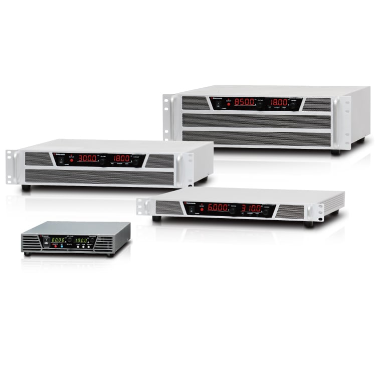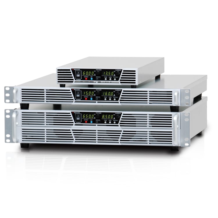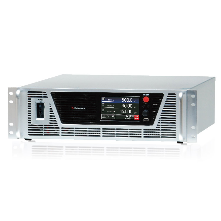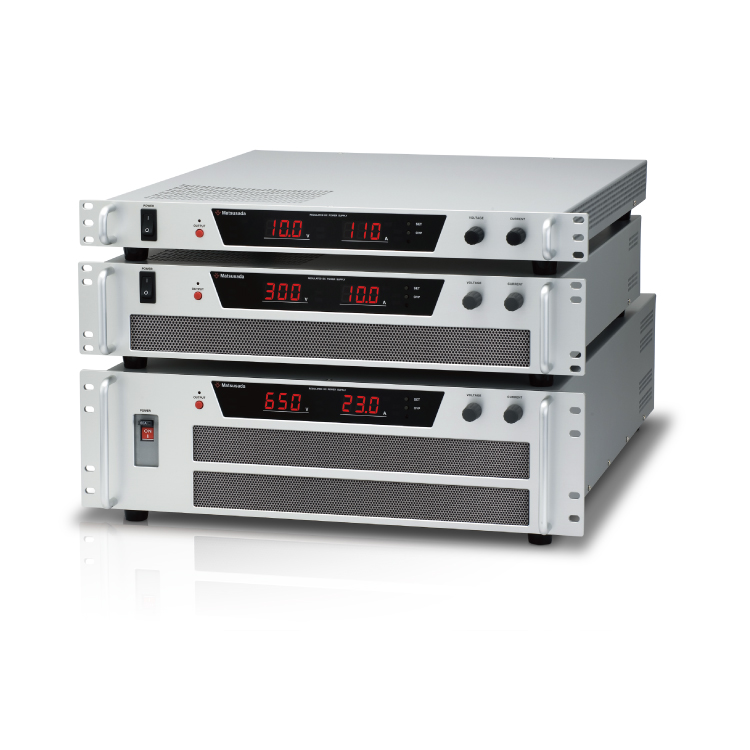
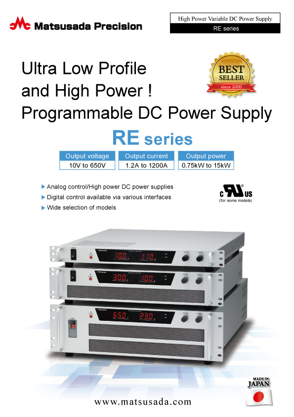
Ultra Low Profile and High Power! Programmable DC Power Supply
- Output voltage: 10 V to 650 V
- Output current: 1.2 A to 1200 A
- Output power: 0.75 kW to 15 kW
- Wide selection of models
The RE series represents a family of compact, high-power, and highly efficient programmable DC power supplies, engineered using our proprietary switching technology.
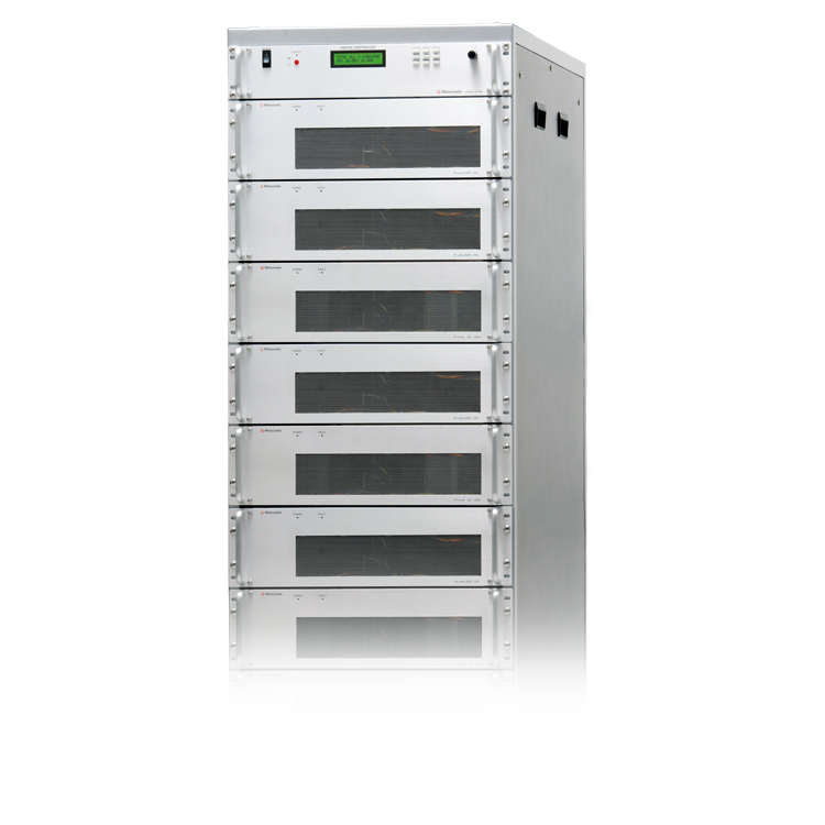
With minimal heat dissipation and a significantly reduced footprint compared to conventional linear power supplies, the RE series enables high-density rack mounting. Its high efficiency reduces operating costs and contributes to a more sustainable working environment. Standard features include extensive remote control and monitoring functions. With an optional digital interface, these units integrate seamlessly into automated systems. Choose from over 140 models with outputs ranging from 10 V to 650 V and 0.75 kW to 15 kW. Power output is expandable up to 60 kW using the master-slave parallel operation feature. (UL Certified models available)
FEATURES AND BENEFITS
- Analog control/High power DC power supplies
- Digital control available via various interfaces
- Wide selection of models
Models
 CERTIFIED MODELS
(Options cannot be added.)
CERTIFIED MODELS
(Options cannot be added.)
| Model | Maximum Output | Ripple *1 | Ripple *2 | Input voltage | ||
|---|---|---|---|---|---|---|
| Voltage | Current | Power | [mVrms] | [mArms] | ||
| RE10-75-L(100V)-UL | 10 V | 75 A | 0.75 kW | 10 mVrms | 150 mArms | 100 V |
| RE10-75-L(200V)-UL | 75 A | 0.75 kW | 10 mVrms | 150 mArms | 200 V | |
| RE10-110-L(100V)-UL | 110 A | 1.1 kW | 10 mVrms | 220 mArms | 100 V | |
| RE10-110-L(200V)-UL | 110 A | 1.1 kW | 10 mVrms | 220 mArms | 200 V | |
| RE15-50-L(100V)-UL | 15 V | 50 A | 0.75 kW | 10 mVrms | 100 mArms | 100 V |
| RE15-50-L(200V)-UL | 50 A | 0.75 kW | 10 mVrms | 100 mArms | 200 V | |
| RE15-80-L(100V)-UL | 80 A | 1.2 kW | 10 mVrms | 160 mArms | 100 V | |
| RE15-80-L(200V)-UL | 80 A | 1.2 kW | 10 mVrms | 160 mArms | 200 V | |
| RE20-38-L(100V)-UL | 20 V | 38 A | 0.76 kW | 10 mVrms | 80 mArms | 100 V |
| RE20-38-L(200V)-UL | 38 A | 0.76 kW | 10 mVrms | 80 mArms | 200 V | |
| RE20-60-L(100V)-UL | 60 A | 1.2 kW | 10 mVrms | 120 mArms | 100 V | |
| RE20-60-L(200V)-UL | 60 A | 1.2 kW | 10 mVrms | 120 mArms | 200 V | |
| RE30-25-L(100V)-UL | 30 V | 25 A | 0.75 kW | 10 mVrms | 50 mArms | 100 V |
| RE30-25-L(200V)-UL | 25 A | 0.75 kW | 10 mVrms | 50 mArms | 200 V | |
| RE30-40-L(100V)-UL | 40 A | 1.2 kW | 15 mVrms | 80 mArms | 100 V | |
| RE30-40-L(200V)-UL | 40 A | 1.2 kW | 15 mVrms | 80 mArms | 200 V | |
| RE35-22-L(100V)-UL | 35 V | 22 A | 0.77 kW | 10 mVrms | 50 mArms | 100 V |
| RE35-22-L(200V)-UL | 22 A | 0.77 kW | 10 mVrms | 50 mArms | 200 V | |
| RE35-34-L(100V)-UL | 34 A | 1.2 kW | 10 mVrms | 70 mArms | 100 V | |
| RE35-34-L(200V)-UL | 34 A | 1.2 kW | 10 mVrms | 70 mArms | 200 V | |
| RE45-17-L(100V)-UL | 45 V | 17 A | 0.765 kW | 18 mVrms | 40 mArms | 100 V |
| RE45-17-L(200V)-UL | 17 A | 0.765 kW | 18 mVrms | 40 mArms | 200 V | |
| RE45-27-L(100V)-UL | 27 A | 1.2 kW | 18 mVrms | 60 mArms | 100 V | |
| RE45-27-L(200V)-UL | 27 A | 1.2 kW | 18 mVrms | 60 mArms | 200 V | |
| RE60-12.5-L(100V)-UL | 60 V | 12.5 A | 0.75 kW | 20 mVrms | 25 mArms | 100 V |
| RE60-12.5-L(200V)-UL | 12.5 A | 0.75 kW | 20 mVrms | 25 mArms | 200 V | |
| RE60-20-L(100V)-UL | 20 A | 1.2 kW | 20 mVrms | 40 mArms | 100 V | |
| RE60-20-L(200V)-UL | 20 A | 1.2 kW | 20 mVrms | 40 mArms | 200 V | |
| RE200-6-L(100V)-UL | 200 V | 6 A | 1.2 kW | 40 mVrms | 15 mArms | 100 V |
| RE200-6-L(200V)-UL | 6 A | 1.2 kW | 40 mVrms | 15 mArms | 200 V | |
| RE200-15-L(200V)-UL | 15 A | 3 kW | 40 mVrms | 30 mArms | 200 V | |
- Rated output voltage when output current is 10% to 100% of rating.
- Rated output current when output voltage is 10% to 100% of rating.
MODELS
| Model | Maximum Output | Ripple *1 | Ripple *2 | ||
|---|---|---|---|---|---|
| Voltage [V] | Current [A] | Power [kW] | [mVrms] | [mArms] | |
| RE10-75 | 10 V | 75 A | 0.75 kW | 10 mVrms | 150 mArms |
| RE10-110 | 110 A | 1.1 kW | 10 mVrms | 220 mArms | |
| RE10-200 | 200 A | 2 kW | 10 mVrms | 400 mArms | |
| RE10-300 | 300 A | 3 kW | 15 mVrms | 600 mArms | |
| RE10-400 | 400 A | 4 kW | 15 mVrms | 800 mArms | |
| RE10-450 | 450 A | 4.5 kW | 30 mVrms | 900 mArms | |
| RE10-750 | 750 A | 7.5 kW | 20 mVrms | 2400 mArms | |
| RE10-820 | 820 A | 8.2 kW | 30 mVrms | 3600 mArms | |
| RE10-1000 | 1000 A | 10 kW | 30 mVrms | 4800 mArms | |
| RE10-1200 | 1200 A | 12 kW | 30 mVrms | 4800 mArms | |
| RE15-50 | 15 V | 50 A | 0.75 kW | 10 mVrms | 100 mArms |
| RE15-80 | 80 A | 1.2 kW | 10 mVrms | 160 mArms | |
| RE15-120 | 120 A | 1.8 kW | 10 mVrms | 250 mArms | |
| RE15-200 | 200 A | 3 kW | 10 mVrms | 400 mArms | |
| RE15-250 | 250 A | 3.75 kW | 15 mVrms | 500 mArms | |
| RE15-300 | 300 A | 4.5 kW | 15 mVrms | 600 mArms | |
| RE15-500 | 500 A | 7.5 kW | 30 mVrms | 2500 mArms | |
| RE15-560 | 560 A | 8.4 kW | 30 mVrms | 2500 mArms | |
| RE15-700 | 700 A | 10.5 kW | 35 mVrms | 3500 mArms | |
| RE20-38 | 20 V | 38 A | 0.76 kW | 10 mVrms | 80 mArms |
| RE20-60 | 60 A | 1.2 kW | 10 mVrms | 120 mArms | |
| RE20-100 | 100 A | 2 kW | 10 mVrms | 200 mArms | |
| RE20-150 | 150 A | 3 kW | 15 mVrms | 300 mArms | |
| RE20-200 | 200 A | 4 kW | 10 mVrms | 400 mArms | |
| RE20-250 | 250 A | 5 kW | 15 mVrms | 500 mArms | |
| RE20-375 | 375 A | 7.5 kW | 30 mVrms | 1200 mArms | |
| RE20-400 | 400 A | 8 kW | 20 mVrms | 2400 mArms | |
| RE20-430 | 430 A | 8.6 kW | 35 mVrms | 2400 mArms | |
| RE20-500 | 500 A | 10 kW | 35 mVrms | 2400 mArms | |
| RE20-600 | 600 A | 12 kW | 30 mVrms | 2400 mArms | |
| RE30-25 | 30 V | 25 A | 0.75 kW | 10 mVrms | 50 mArms |
| RE30-40 | 40 A | 1.2 kW | 15 mVrms | 80 mArms | |
| RE30-65 | 65 A | 1.95 kW | 20 mVrms | 130 mArms | |
| RE30-100 | 100 A | 3 kW | 20 mVrms | 200 mArms | |
| RE30-130 | 130 A | 3.9 kW | 30 mVrms | 260 mArms | |
| RE30-170 | 170 A | 5.1 kW | 30 mVrms | 340 mArms | |
| RE30-250 | 250 A | 7.5 kW | 20 mVrms | 500 mArms | |
| RE30-290 | 290 A | 8.7 kW | 30 mVrms | 700 mArms | |
| RE30-350 | 350 A | 10.5 kW | 30 mVrms | 800 mArms | |
| RE30-400 | 400 A | 12 kW | 20 mVrms | 800 mArms | |
| RE35-22 | 35 V | 22 A | 0.77 kW | 10 mVrms | 50 mArms |
| RE35-34 | 34 A | 1.2 kW | 10 mVrms | 70 mArms | |
| RE35-60 | 60 A | 2.1 kW | 20 mVrms | 120 mArms | |
| RE35-85 | 85 A | 3 kW | 20 mVrms | 170 mArms | |
| RE35-115 | 115 A | 4 kW | 20 mVrms | 230 mArms | |
| RE35-140 | 140 A | 4.9 kW | 30 mVrms | 280 mArms | |
| RE35-215 | 215 A | 7.5 kW | 35 mVrms | 1800 mArms | |
| RE35-240 | 240 A | 8.4 kW | 35 mVrms | 2000 mArms | |
| RE35-300 | 300 A | 10.5 kW | 35 mVrms | 2000 mArms | |
| RE35-340 | 340 A | 11.9 kW | 35 mVrms | 2400 mArms | |
| RE40-100 | 40 | 100 A | 4 kW | 30 mVrms | 300 mArms |
| RE40-220 | 220 A | 8.8 kW | 30 mVrms | 350 mArms | |
| RE45-17 | 45 V | 17 A | 0.765 kW | 18 mVrms | 40 mArms |
| RE45-27 | 27 A | 1.2 kW | 18 mVrms | 60 mArms | |
| RE45-45 | 45 A | 2 kW | 30 mVrms | 90 mArms | |
| RE45-66 | 66 A | 3 kW | 30 mVrms | 130 mArms | |
| RE45-90 | 90 A | 4 kW | 30 mVrms | 180 mArms | |
| RE45-110 | 110 A | 5 kW | 45 mVrms | 220 mArms | |
| RE45-165 | 165 A | 7.5 kW | 45 mVrms | 750 mArms | |
| RE45-220 | 220 A | 9.9 kW | 45 mVrms | 1100 mArms | |
| RE45-260 | 260 A | 11.7 kW | 45 mVrms | 1300 mArms | |
| RE60-12.5 | 60 V | 12.5 A | 0.75 kW | 20 mVrms | 25 mArms |
| RE60-20 | 20 A | 1.2 kW | 20 mVrms | 40 mArms | |
| RE60-35 | 35 A | 2.1 kW | 15 mVrms | 70 mArms | |
| RE60-50 | 50 A | 3 kW | 20 mVrms | 100 mArms | |
| RE60-67 | 67 A | 4 kW | 20 mVrms | 135 mArms | |
| RE60-83 | 83 A | 5 kW | 30 mVrms | 170 mArms | |
| RE60-125 | 125 A | 7.5 kW | 30 mVrms | 350 mArms | |
| RE60-140 | 140 A | 8.4 kW | 30 mVrms | 350 mArms | |
| RE60-170 | 170 A | 10.2 kW | 35 mVrms | 500 mArms | |
| RE60-200 | 200 A | 12 kW | 35 mVrms | 500 mArms | |
| RE60-220 | 220 A | 13.2 kW | 35 mVrms | 500 mArms | |
| RE60-250 | 250 A | 15 kW | 25 mVrms | 500 mArms | |
| RE80-110 | 80 V | 110 A | 8.8 kW | 80 mVrms | 600 mArms |
| RE100-7.5 | 100 V | 7.5 A | 0.75 kW | 20 mVrms | 15 mArms |
| RE100-12 | 12 A | 1.2 kW | 20 mVrms | 25 mArms | |
| RE100-20 | 20 A | 2 kW | 20 mVrms | 40 mArms | |
| RE100-30 | 30 A | 3 kW | 30 mVrms | 60 mArms | |
| RE100-40 | 40 A | 4 kW | 30 mVrms | 80 mArms | |
| RE100-50 | 50 A | 5 kW | 40 mVrms | 100 mArms | |
| RE100-75 | 75 A | 7.5 kW | 60 mVrms | 300 mArms | |
| RE100-84 | 84 A | 8.4 kW | 60 mVrms | 350 mArms | |
| RE100-100 | 100 A | 10 kW | 100 mVrms | 800 mArms | |
| RE100-150 | 150 A | 15 kW | 100 mVrms | 1000 mArms | |
| RE150-5 | 150 V | 5 A | 0.75 kW | 30 mVrms | 10 mArms |
| RE150-8 | 8 A | 1.2 kW | 30 mVrms | 20 mArms | |
| RE150-14 | 14 A | 2.1 kW | 25 mVrms | 30 mArms | |
| RE150-20 | 20 A | 3 kW | 30 mVrms | 40 mArms | |
| RE150-27 | 27 A | 4 kW | 30 mVrms | 55 mArms | |
| RE150-33 | 33 A | 5 kW | 60 mVrms | 70 mArms | |
| RE150-50 | 50 A | 7.5 kW | 70 mVrms | 100 mArms | |
| RE150-56 | 56 A | 8.4 kW | 70 mVrms | 100 mArms | |
| RE150-70 | 70 A | 10.5 kW | 150 mVrms | 200 mArms | |
| RE150-100 | 100 A | 15 kW | 100 mVrms | 200 mArms | |
| RE160-27 | 160 V | 27 A | 4.3 | 30 mVrms | 55 mArms |
| RE160-55 | 55 A | 8.8 kW | 160 mVrms | 200 mArms | |
| RE200-3.8 | 200 V | 3.8 A | 0.76 kW | 40 mVrms | 10 mArms |
| RE200-6 | 6 A | 1.2 kW | 40 mVrms | 15 mArms | |
| RE200-10 | 10 A | 2 kW | 40 mVrms | 20 mArms | |
| RE200-15 | 15 A | 3 kW | 40 mVrms | 30 mArms | |
| RE200-20 | 20 A | 4 kW | 200 mVrms | 40 mArms | |
| RE200-25 | 25 A | 5 kW | 200 mVrms | 50 mArms | |
| RE200-37 | 37 A | 7.4 kW | 200 mVrms | 280 mArms | |
| RE200-42 | 42 A | 8.4 kW | 150 mVrms | 200 mArms | |
| RE200-50 | 50 A | 10 kW | 200 mVrms | 380 mArms | |
| RE200-75 | 75 A | 15 kW | 200 mVrms | 530 mArms | |
| RE250-35 | 250 V | 35 A | 8.7 kW | 100 mVrms | 150 mArms |
| RE300-2.5 | 300 V | 2.5 A | 0.75 kW | 50 mVrms | 5 mArms |
| RE300-4 | 4 A | 1.2 kW | 50 mVrms | 10 mArms | |
| RE300-6.5 | 6.5 A | 2 kW | 50 mVrms | 15 mArms | |
| RE300-10 | 10 A | 3 kW | 50 mVrms | 20 mArms | |
| RE300-13 | 13 A | 3.9 kW | 300 mVrms | 30 mArms | |
| RE300-16 | 16 A | 4.8 kW | 300 mVrms | 35 mArms | |
| RE300-25 | 25 A | 7.5 kW | 100 mVrms | 50 mArms | |
| RE300-28 | 28 A | 8.4 kW | 100 mVrms | 50 mArms | |
| RE300-35 | 35 A | 10.5 kW | 300 mVrms | 100 mArms | |
| RE300-50 | 50 A | 15 kW | 150 mVrms | 100 mArms | |
| RE350-21 | 350 V | 21 A | 7.35 kW | 150 mVrms | 100 mArms |
| RE350-24 | 24 A | 8.4 kW | 150 mVrms | 100 mArms | |
| RE350-28 | 28 A | 9.8 kW | 150 mVrms | 100 mArms | |
| RE350-42 | 42 A | 14.7 kW | 150 mVrms | 100 mArms | |
| RE400-18.7 | 400 V | 18.7 A | 7.5 kW | 200 mVrms | 100 mArms |
| RE400-37.5 | 37.5 A | 15 kW | 200 mVrms | 100 mArms | |
| RE450-16.7 | 450 V | 16.7 A | 7.5 kW | 200 mVrms | 50 mArms |
| RE450-33.3 | 33.3 A | 15 kW | 200 mVrms | 100 mArms | |
| RE500-1.5 | 500 V | 1.5 A | 0.75 kW | 150 mVrms | 5 mArms |
| RE500-2.4 | 2.4 A | 1.2 kW | 150 mVrms | 5 mArms | |
| RE500-4 | 4 A | 2 kW | 150 mVrms | 10 mArms | |
| RE500-6 | 6 A | 3 kW | 150 mVrms | 15 mArms | |
| RE500-8 | 8 A | 4 kW | 500 mVrms | 20 mArms | |
| RE500-10 | 10 A | 5 kW | 500 mVrms | 20 mArms | |
| RE500-15 | 15 A | 7.5 kW | 200 mVrms | 50 mArms | |
| RE500-17 | 17 A | 8.5 kW | 200 mVrms | 50 mArms | |
| RE500-20 | 20 A | 10 kW | 500 mVrms | 100 mArms | |
| RE500-30 | 30 A | 15 kW | 200 mVrms | 100 mArms | |
| RE600-12.5 | 600 V | 12.5 A | 7.5 kW | 100 mVrms | 25 mArms |
| RE600-25 | 25 A | 15 kW | 100 mVrms | 50 mArms | |
| RE650-1.2 | 650 V | 1.2 A | 0.78 kW | 200 mVrms | 5 mArms |
| RE650-1.8 | 1.8 A | 1.2 kW | 200 mVrms | 5 mArms | |
| RE650-3 | 3 A | 2 kW | 200 mVrms | 10 mArms | |
| RE650-4.5 | 4.5 A | 2.9 kW | 200 mVrms | 10 mArms | |
| RE650-6 | 6 A | 3.9 kW | 200 mVrms | 15 mArms | |
| RE650-7.7 | 7.7 A | 5 kW | 200 mVrms | 20 mArms | |
| RE650-11 | 11 A | 7.2 kW | 200 mVrms | 50 mArms | |
| RE650-13.5 | 13.5 A | 8.8 kW | 250 mVrms | 50 mArms | |
| RE650-16 | 16 A | 10.4 kW | 250 mVrms | 50 mArms | |
| RE650-23 | 23 A | 15 kW | 300 mVrms | 100 mArms | |
- Rated output voltage when output current is 10% to 100% of rating.
- Rated output current when output voltage is 10% to 100% of rating.
Functions
Remote control connector (TB1)
Note: The signal common of TB1 is internally connected to the negative output terminal. To prevent ground loops or short circuits, ensure that the external control signal connected to TB1 is electrically floating (isolated from the ground).-
REMOTE/LOCAL change
As for the output voltage control, output current control, and overvoltage protection, the remote/local mode can be individually switched by relay or TTL signal. -
External output ON/OFF
Output can be turned ON/OFF by relay or TTL signal.
The logic of the signal can be selected by entering 5 V. - Output voltage control
- Output current control
- Overvoltage protection
- Output monitor (Voltage, Current)
-
Output of status
Common is floating with the output of the open collector for each COMMON.
Function setting switch (SW1)
-
Output voltage control
0 to 10 V Local ⇔ 0 to 10 kΩ approx. -
Output current control
0 to 10 V Local ⇔ 0 to 10 kΩ approx. -
Overtemperature protection
Manual reset ⇔ Auto reset -
Output state auto-recovery prevention (former: power failure protection)
ON ⇔ OFF (ON/OFF by AC)
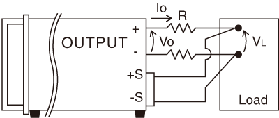
Remote sensing
Prevents voltage drop-down (Vo-VL) due to resistance (R) or deterioration of stability by contact resistance (Max 0.5 V)
Output terminal
The form differs depending on the MODEL. Please check which form is in dimension.
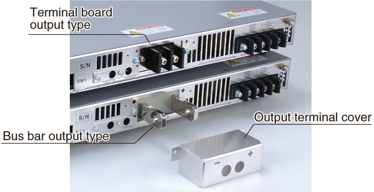
* The protective cover for terminal board models features two 8 mm diameter holes for cabling as standard. Covers with larger diameter holes are available upon request.
Please contact us for details.
Specifications
- Input voltage
-
100 Vac, 50/60 Hz, Single-phase (UL certified models)
200 Vac, 50/60 Hz, Single-phase (UL certified models)
200 Vac, 50/60 Hz, Three-phase (UL certified models)
115 Vac ±10%, 50/60 Hz, Single-phase
220 Vac ±10%, 50/60 Hz, Single-phase
230 Vac ±10%, 50/60 Hz, Single-phase
220 Vac ±10%, 50/60 Hz, Three-phase
400 Vac ±10%, 50/60 Hz, Three-phase (Option)
440 Vac ±10%, 50/60 Hz, Three-phase (Option) - Output voltage control
-
[Local] Rotary encoder on front panel
[Analog remote] External control voltage 0 to 10 Vdc or external 10kΩ potentiometer
[Digital remote] Command (option) - Output current control
-
[Local] Rotary encoder on front panel
[Analog remote] External control voltage 0 to 10 Vdc or external 10kΩ potentiometer
[Digital remote] Command (option)
| MODEL (Output power) |
Input voltage (±10% AC50/60 Hz) |
Phase | Input current | Input current protection | |||
|---|---|---|---|---|---|---|---|
| When PFC (Typ.) *1 |
Normal (Typ.) *1 |
Rush (p-p) |
|||||
| 0.75 kW to 0.78 kW | 115V | 1 | - | 12 A | 60 A | Fuse 30 A | |
| 230 V | 8 A | ||||||
| 1.1 kW to 1.2 kW | 115 V | 1 | - | 19 A | 90 A | ||
| 230 V | 11 A | ||||||
| 1.8 kW to 2.1 kW | 220V | 1/3 | - | 17A/10 A | 100 A | ||
| 2.9 kW to 3 kW | 220 V | 3 | - | 14 A | 100 A | ||
| 3.75 kW to 4 kW | 220 V | 3 | 15 A | 19 A | 100 A | Circuit protector 30 A | |
| 4.3 kW to 5.1 kW | 220 V | 3 | 16 A | 23 A | |||
| 7.2 kW to 7.5 kW | 10 V, 15 V | 220 V | 3 | 26 A *2 | 35 A | 100 A | Circuit protector 60 A |
| 20 V to 60 V | 34 A | ||||||
| over 100 V | 25 A *2 | 33 A | |||||
| 8 kW to 10.5 kW | 10V, 15V | 220 V | 3 | 36 A | 46 A | 100 A | |
| 20 V to 60 V | 34 A | 44 A | |||||
| 80 V to 100 V | 32 A *3 | 41 A | |||||
| 11.7 kW to 12 kW | 220 V | 3 | 40 A *3 | 54 A | 150 A | Circuit protector 100 A | |
| 13.2 kW to 15 kW | 220 V | 3 | 50 A *3 | 68 A | |||
- At rated input voltage
- Circuit protector 30 A
- Circuit protector 60 A
For more specification details, download the datasheet below.
FAQs
- How should I choose a circuit breaker for a high-power DC power supply?
- Can we use multiple thin wires to connect the power supply to the load instead of thick wires?
- We are concerned that the output terminal is equipped with a metal cover. Is it safe to use it as it is?
- What precautions should be taken for parallel connection of the power supplies?
- Do you have any tips for extending the service life of power supplies?
Options
- -LCP *2 *3
-
Constant power control
(Voltage control is eliminated. Limited at maximum rated voltage)
- -LEt *2
-
LAN interface port
- -LGb *1
-
GPIB interface port (Scheduled for discontinuation in December 2028)
- -LGob *1 *2
-
Optical interface port
This option changes the standard interfaces to a built-in optical interface port. By combining this option with an adapter for optical connection (sold separately), communication between the control device and the power supply can be controlled in an isolated state. Be sure to select this option when using the product in the following environments.- -LGob: optical port + optical cable 2 meters
- -LGob(Fc5): optical interface port + optical cable 5 meters
- -LGob(Fc10): optical interface port + optical cable 10 meters
- -LGob(Fc20): optical interface port + optical cable 20 meters
- -LGob(Fc40): optical interface port + optical cable 40 meters
Select the optional build-in optical port (-LGob) when using this DC power supply under the following conditions.
- Noisy environments such as factories (example: when motors or coils are used near loads or power sources).
- If this power supply and your controller (PC or PLC) cannot be installed within 2 meters.
- When there is a possibility of arcing or output short-circuit.
To use the optical interface, you need to prepare an optical interface adapter separately. For details, click here.
- Lls/-LIs10 *1
-
Isolated remote control
Output control signal is isolated from common (=outputΘ) so that floating of the control signal is not required when negative output operation or series connection
(isolation voltage from outputΘ is below 250 V)-
Output control
[-LIs] CV: External control voltage 0 to 5 Vdc, CC: External control voltage 0 to 5 Vdc
[-LIs10] CV: External control voltage 0 to 10 Vdc, CC: External control voltage 0 to 10 Vdc -
Monitor output
[-LIs] Output voltage monitor: 5 V/Maximum output voltage, Output current monitor: 5 V/Maximum output current
[-LIs10] Output voltage monitor: 10 V/Maximum output voltage, Output current monitor: 10 V/Maximum output current -
Other functions
[-LIs/-LIs10] External output ON/OFF, Status signal output (CC, OUTPUT and Stand-by)
-
Output control
- -LLp
-
10-turn potentiometer with lock (both voltage and current)
Only for models less than 300 V
- -LOcp *4
-
Overcurrent protection (OCP)
Cut off the output at the set current value. Local setting only.
Setting range: 5% to 110% of maximum rated current, Local setting: 1-turn volume on front panel
Reset: Manual recovery by OUTPUT switch or External output ON/OFF
- -LPfc *4
-
Power factor correction circuit (Three-phase input of 3.75 kW to 15 kW type only)
Size of the case will be different. Contact the nearby sales office for more details about this option.
- -LUs1 *1
-
USB interface port
- -L(220V)
-
Input voltage: 220 Vac ±10%
For 0.75 kW to 1.2 kW models, Change the original input voltage of 230 V to 220 V. Input current will be about 105% of typical value
- -L(230V)
-
Input voltage: 230 Vac ±10%
For 1.8 kW to 15 kW models, Change the original input voltage of 220 V to 230 V. Input current will be about 95% of typical value
- -L(240V)
-
Input voltage: 240 Vac ±10%
For the original input voltage of 220 V models, Change the input voltage to 240 V. Input current will be about 95% of typical value For the original input voltage of 230 V models, Change the input voltage to 240 V. Input cur rent will be about 90% of typical value
- -L(400V)
-
Input voltage: 400 Vac ±10%
For 7.5 kW to 15 kW models
The size of the case will be different. Contact the nearby sales office for more details about this option.
- -L(440V)
-
Input voltage: 440 Vac ±10%
For 7.5 kW to 15 kW models
The size of the case will be different. Contact the nearby sales office for more details about this option.
- Only one of these remote control options can be selected. If you are considering digital control from a computer, we recommend selecting the optical interface (-LGob), which is resistant to noise, and using it with our separately sold adapter.
- The constant power control option (-LCp) cannot be selected together with any of the remote control options (-LEt, -LGb, -LGob, -LIs, -LIs10, -LUs1).
- The constant power control option (-LCp) and the overcurrent protection option (-LOcp) cannot be selected simultaneously.
- -LPfc and -L(400V) or -L(440V) cannot be chosen simultaneously.
How to Order
When placing an order, please list the option symbols after the model name in alphabetical order. When selecting multiple options, omit “-L” from the second and subsequent option symbols. The option for changing the input voltage should be listed last.
<Example> RE15-250-LGob(Fc5)LpPfc(240V), RE100-100-LCpIs10LpOcp(400V)
Please ask our offices for a Three-phase AC input cable.
Optional Add on Program for Build-in Digital Interface
- Sweep control program for -LEt, -LGb, -LGob, -LUs1
-
This program allows for gradual output changes (ramp/sweep control) compatible with our digital controller adapters. Users can define start and end values for voltage and current, as well as the duration, to create custom output patterns. This feature is ideal for applications requiring specific voltage/current profiles, such as capacitor forming, electronic component aging, and semiconductor burn-in testing.
where it is necessary to repeat the output by changing the output gently and a decided pattern.For more specification details, download the datasheet below.
Accessories
- AC input cable
-
Included accessory
0.75 kW to 2.1 kW
single-phase input models on availableCABLE TYPE5 

250 V/25 A 2.5 meters Additional accessory
1.8 kW to 3 kW
three-phase input models on availableCABLE TYPE6 

250 V/25 A 2.5 meters Additional accessory
3.75 kW to 15 kW models on availableCABLE TYPE7 

250 V/75 A 10 meters Select an appropriate AC input cable according to your operating environment and region.
Please ask our sales offices for a three-phase input AC cable.
- Optical isolation adapter
-
To use the optical interface, you need to prepare an optical interface adapter separately. The following interface adapters are available according to your controller port.
- CO-E32: LAN to optical interface adapter
- USB-OPT: USB to optical interface adapter
- CO-OPT2-9: RS-232C (9 pin) to optical interface adapter
- CO-OPT2-25: RS-232C (25 pin) to optical interface adapter
- CO-OPT4-25: RS-485 (25 pin) to optical interface adapter
- CO-G32: GPIB to optical interface adapter
(Scheduled for discontinuation in December 2028)
Example of communication with optical fiber  For details, refer to CO/USB series
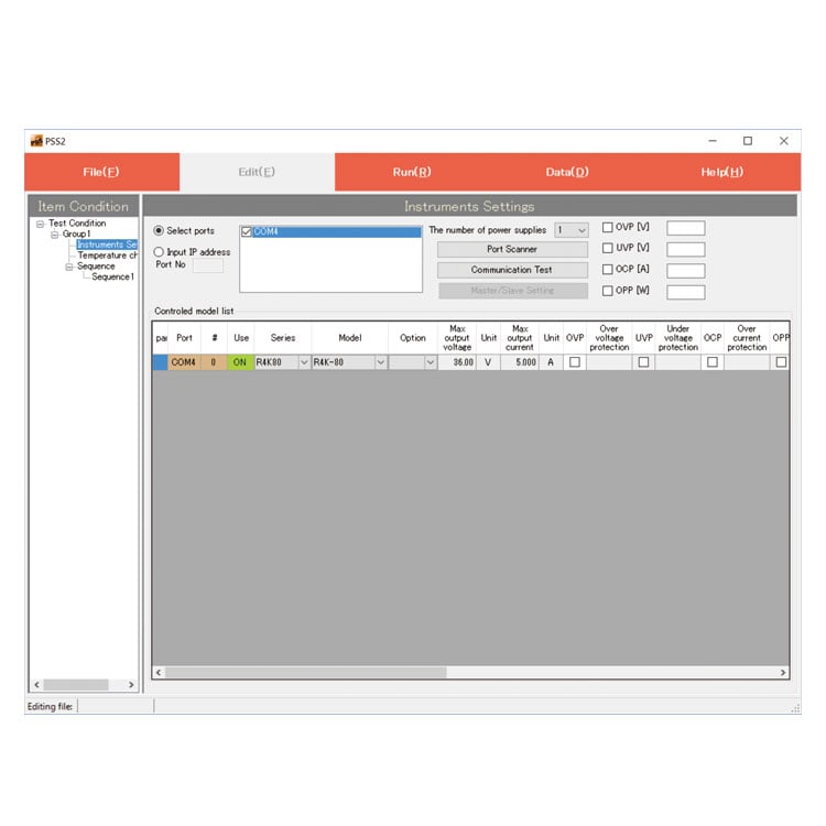
- Application software
-
PSS2en series: Remote control, Test workflow design, and Data logging
Click here for the PSS2en seriesPSS2en is the dedicated software that can actuate various power supplies, electronic loads, and digital controllers for power supplies manufactured by Matsusada Precision Inc. with a simple setup.
It is perfect for the aging test, the burn-in test, and the withstand voltage test for electronic parts, as well as for the endurance test, intermittent/continuous operation test, or various simulation tests for automobile electric components.

Dimensions
Download
If you are unable to download a file
Please try the following solution.
- Please press Ctrl+F5 to clear the cache of your web browser and try again.
- Please restart your web browser and log in again to try again.
- Please change your web browser to another browser and try again.
- Restart the computer and try again.
- Please try again on a different computer.
-
RE series Datasheet
Date: 2025-10-31 rev 29
PDF (3,346 KB)
-
DC POWER SUPPLIES SELECTION GUIDE
Date: 2025-06-27 rev.02
PDF (5,265 KB)

-
How to Use DC Power Supplies
Date: 2025-11-11 rev 09
PDF (1,281 KB)

-
RE series Instruction Manual
Last updated: December 19, 2019 rev.1.1
PDF (780 KB)
-
RE/REH/RF series Instruction Manual (LGb/LGob/LUs1 option)
Date: 2020-05-26 rev0.6
PDF (601 KB)
-
USB driver (-LUs1 Option) for Windows 10, 11
Date: 2025-12-19 rev 2.12.36.20
ZIP(1,629KB)
-
USB driver (-LUs1 Option) for Windows XP, 7, 8, 8.1
Date: 2025-01-22 rev 1.7.6
ZIP (6,504 KB)

-
RE series Outline Drawing (DXF, PDF)
Date: 2024-07-25
ZIP (2,601 KB)
Login Required
-
RE series Datasheet
Date: 2025-10-31 rev 29
PDF (3,346 KB)
-
DC POWER SUPPLIES SELECTION GUIDE
Date: 2025-06-27 rev.02
PDF (5,265 KB)
-
How to Use DC Power Supplies
Date: 2025-11-11 rev 09
PDF (1,281 KB)
-
RE series Instruction Manual
Last updated: December 19, 2019 rev.1.1
PDF (780 KB)
-
RE/REH/RF series Instruction Manual (LGb/LGob/LUs1 option)
Date: 2020-05-26 rev0.6
PDF (601 KB)
-
USB driver (-LUs1 Option) for Windows 10, 11
Date: 2025-12-19 rev 2.12.36.20
ZIP(1,629KB)
-
USB driver (-LUs1 Option) for Windows XP, 7, 8, 8.1
Date: 2025-01-22 rev 1.7.6
ZIP (6,504 KB)
-
RE series Outline Drawing (DXF, PDF)
Date: 2024-07-25
ZIP (2,601 KB)
On this website, we provide only the latest versions of information and instruction manuals for our products. Therefore, the newest versions of manuals on the website may differ from those that came with products you purchased in the past.