PROGRAMMABLE WIDE RANGE
DC POWER SUPPLY
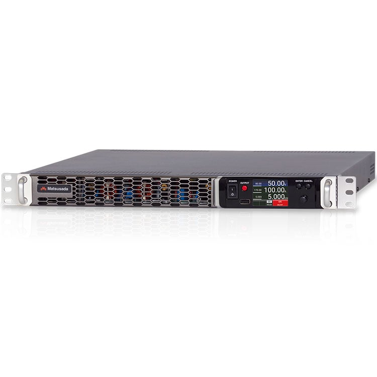
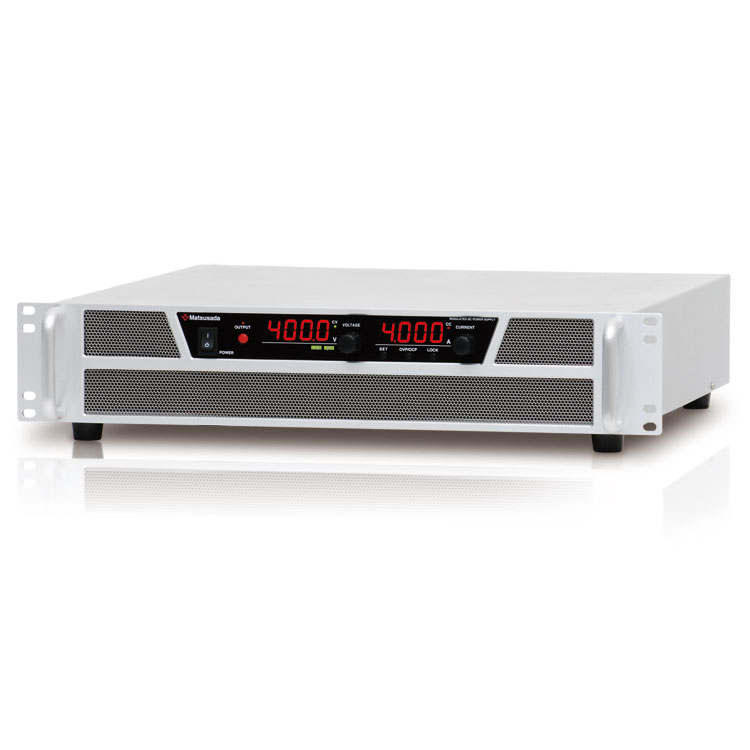
High Power Density with Maximum Output 5kW in 1U Chassis
- Voltage range: 80V to 900V
- Current: 16.7A to 170A
- Power: 5kW autoranging
- Monitoring controlling web server
Autoranging with 3 times the voltage and Current available for flexible operation
PRKT series is a DC power supply equipped with a turbo function, enabling a wide range of voltage/current three times higher than previous DC power supplies with approximately the same rated output power.
The PRKT series all allows flexible voltage and current output within its rated power, resulting user not to required to search for a power supply with unnecessary wider rated voltage and current. Thus single PRKT unit can be used for much wider user applications.
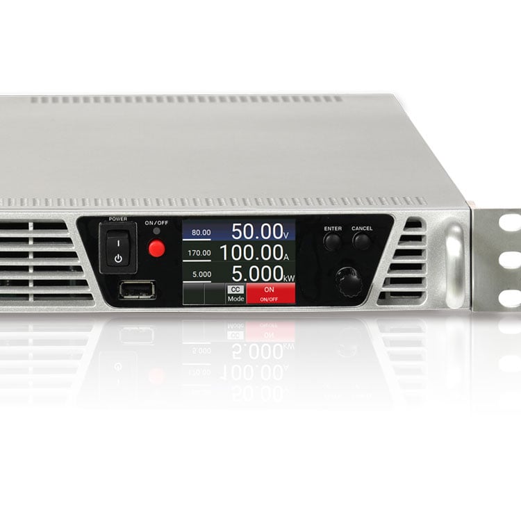
Not only its a wide range of output, but the general performance of the power supply is pursued to achieve overwhelming quality, providing a power factor correction circuit with 0.99 power factor, a color display panel having excellent visibility, and adoption of a speedy and excellent precision rotary encoder.
- Color LCD display for program operation.
- Data log function to save log data of output voltage and current in USB memory
- Constant power control (CP mode) providing constant power output easily.
FEATURES
- Equipped with a turbo function to achieve an autoranging of output
- CV/CC priority setting function enables suppression of overshoot by setting the increase/decrease voltage/current sequence when output is turned ON
- Variable internal resistance function enables simple simulation of rechargeable batteries, photovoltaic cells, fuel cells, etc.
- The sink current suppression is used to reduce the reverse current flowing from the load to the unit in order to prevent a voltage drop on the load as the output is OFF or the set voltage is lowered.
- Ideal for research & development with its low-noise switching method
APPLICATIONS
-
Test and Measurement
Test and Measurement for electronic circuits, devices, components, equipment -
Quality control and Industrial automation
Automated Test Equipment (ATE), Requires adequate product evaluation and testing -
Telecommunications equipment
DC power supply and evaluation testing of servers, routers, and other communications equipment -
Semiconductor processing
Semiconductor manufacturing equipment such as Photolithography, Vapor deposition, Evaporation
heating, Ion implantation DC power supplies for RF, electromagnets, beam steering, and heaters
-
Burn-in testing
Burn-in testing for semiconductor devices and electronic components -
Renewable energy
Development of Hydrogen and Ammonia production equipment, Fuel cells, Solar cells, Batteries, Wind turbines, Power inverters, DC-DC converters -
Scientific research, Medical equipment, etc
The PRKT series has been designed to suit a wide variety of DC power supply needs.
Models
| Model | Maximum Output | ||
|---|---|---|---|
| Voltage | Current | Power | |
| PRKT80V170A5kW | 80 V | 170 A | 5 kW |
| PRKT300V50A5kW | 300 V | 50 A | |
| PRKT500V30A5kW | 500 V | 30 A | |
| PRKT900V16.7A5kW | 900 V | 16.7 A | |
Functions
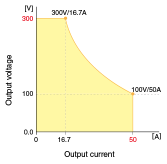
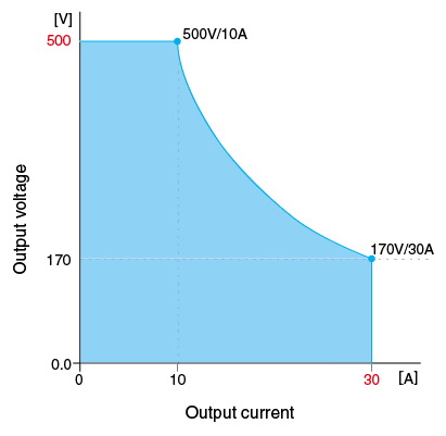
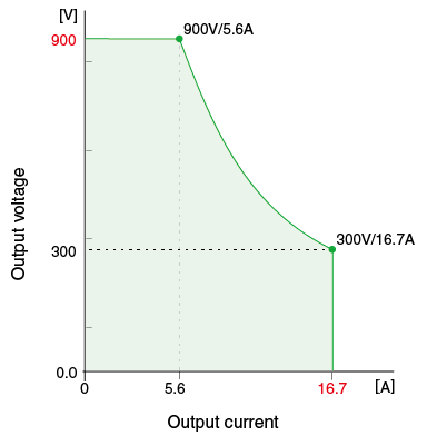
Output range graphs
With the turbo function, a wide range of voltage and current output compared to conventional DC power supplies.

Front Panel USB Port Available
USB memory connected to the USB port on the front panel enables a data logging function and built-in sequence program input/output function.
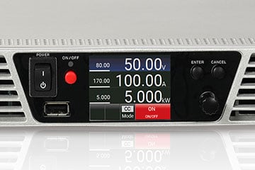
No data logger or no always connected computer required
Shortening time of wiring and preparation, Suited for cycle tests in areas where computers are prohibited.
•Features:Built-in data logging
Data logging captures the output data at the fastest interval of 0.1 seconds by inserting the USB memory stick. Also, with the dedicated software MLV, the log data is available in CSV format to output.
•Use in places where you cannot always connect a computer
With the dedicated software MSS, you can save the sequence program data to the USB memory and load it from the front USB port. Thus, the program operation is available by the power supply only.
Application Software
Two dedicated application software packages are included as standard accessories to maximize the use of the front panel USB port.
(1) Sequence function: MSS (Matsusada Sequence Software)
Easy to use for beginners
With MSS, the dedicated software, you can create sequence data using a PC. The software makes it easier and more convenient to create sequence data. The created sequence data can be saved to USB memory, and up to 1,024 steps of the sequence program can be loaded.
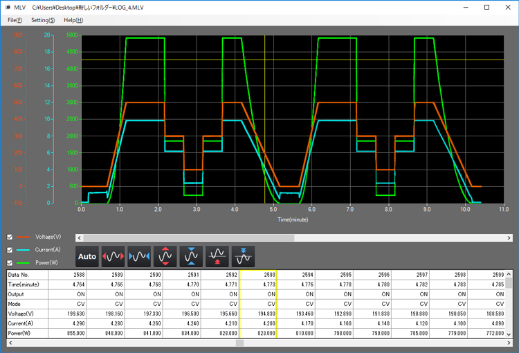
(2) Operation log display: MLV (Matsusada Log Viewer)
Instant graphing of operation logs
Operation log display function: MLV, the dedicated software can read and graph the operation log. Logging to USB memory is available not only during the sequence operation as described in (1) above, but also during the local/external control.
Easy editing of operation logs
MLV can select items you need and save them in CSV format, so you can also edit the data in spreadsheet software with no problem.
[Display items]
- Elapsed time
- CC/CV mode
- Output value (voltage, current, and power)
- Status
- Other information on errors, etc.
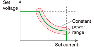
Constant Power Control Function (CP mode)
In addition to Constant Voltage control (CV mode) and Constant Current control (CC mode), Constant Power Control (CP mode) is provided.
With CP mode, a constant power supply is provided depending on loads, such as resistors (heaters) whose resistance changes with temperature. It is available without monitoring voltage/current or attaching external control devices (temperature regulators).
CV/CC Priority Setting Function
CV (Constant Voltage) priority/CC (Constant Current) priority modes can be selected and set. As is the case with diodes, a load tends to suddenly change the resistance at certain points. When the device is started in CV mode, the current will be a momentary overshot. Using the PRKT series, the occurrence of overshoot can be suppressed by selecting CC priority mode. The function can reduce the risk of damaging expensive loads such as high-power laser diodes.
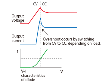

* Overshoot is less likely to occur as the CC value is set to the lowest in the range where the CC state can keep not by releasing the voltage setting even in the CC priority mode.
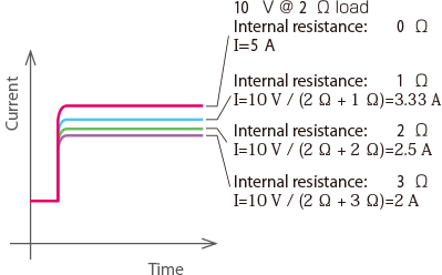
Variable Internal Resistance Function (in CV mode)
A value set to the causes a voltage drop when the load current flows. Batteries, Photovoltaic cells, and Fuel cells can be simulated. (The setting range of the internal resistance value is from 0 Ω to the rated voltage/rated current.)
Sink Current Suppression
When supplying power to loads with capacities like batteries and capacitors, the sink current suppression is used to reduce the reverse current flowing from the load to the unit in order to prevent a voltage drop on the load as the output is OFF or the set voltage is lowered.
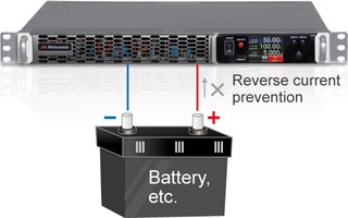
Note: Reverse current cannot be controlled and stabilized. Connect a dummy resistor or reverse current prevention diode when load of the reverse voltage is equal to or higher than the rated voltage (inductive loads, regenerative motors, etc.).
Supports Expansion with MASTER/SLAVE Control
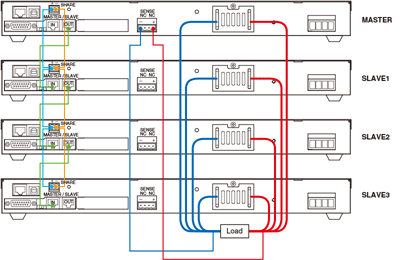
Wide range output with parallel connections up to four units (20 kW).
- Expandable to a total of four MASTER and SLAVE units (20 kW).
- During MASTER/SLAVE connections, values of output voltage/current for the overall unit are displayed on the output voltage/current meter of the MASTER.
(Individual output values are not displayed on the output voltage/current meter of each SLAVE.)
Note: Make sure to use the same length of all the cables to connect to each load from the main unit.
*Dedicated cable for master-slave connection is available.
We offer a set of a parallel control cable and a cable with an attached shared terminal.
Two-mode Lock Function
The locking is selectable from two setting modes: one is “Full LOCK” to lock all front panel operations, and the other is “Normal LOCK” to lock everything except for the ON/OFF switch.
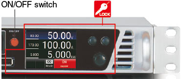 *In both “Full” and “Normal” modes, an Emergency stop is enabled with the POWER ON/OFF
switch
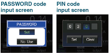
“Password Function” a new protection using password along with “Two-mode Lock Function” New
In this function, to cancel the two-mode lock function, input a 4-digit PIN code. (Enable/Disable is selectable.)
Preset Memory Function
With the preset memory function, the preset values are automatically saved when turning power off. Furthermore, up to three different voltage, current, and power settings are also memorized respectively.
External Analog Control
Easy connection to control devices thanks to independent external analog control of the output!
The control signal is isolated from the output. So, when you operate the analog control with the control device or series operation, floating of a control signal is no longer required.
-
External output ON/OFF
The output can be turned ON/OFF by the external relay or TTL signal.
The logic of the signal can be selected by 5 V input. -
Remote sensing
It ensures the prevention of stability deterioration caused by the voltage drop (VO-VL) by the resistance (R) of the output wire and the contact resistance (up to 0.5 V). -
Remote/Local mode setting
Voltage, Current, Power, Overvoltage protection, Overcurrent protection and Overpower protection, can be switched by relay or TTL signal. -
Output monitor(Voltage, Current)
-
Output control (Voltage/Current/Power/Overvoltage protection/Overcurrent protection/Overpower protection)
Select only the functions you need ! Prepare the lowest command voltage !
Up to three settings are selectable in voltage, current, power, OVP, OCP, and OPP. You only need to have the command voltage for the items by external control, which can help reduce costs and manhours for design.
(For items not selected, the main unit setting values will be reflected.) -
Status output
Flexible error detection function!
Specifications
Options
- -LCa *
-
CAN interface port
Using CAN communications, output controlling and operation status monitoring of these devices can be performed.
- -LGob *
-
Optical interface port
- -LGob: Optical interface port + optical cable 2 meters
- -LGob(Fc5): Optical interface port + optical cable 5 meters
- -LGob(Fc10): Optical interface port + optical cable 10 meters
- -LGob(Fc20): Optical interface port + optical cable 20 meters
- -LGob(Fc40): Optical interface port + optical cable 40 meters
With optical communication, isolation control is performed. As complete isolation is performed by means of optical fiber, this enables advanced prevention of erroneous operation involved with transient phenomenon caused by surges, inductive lightning, external noise, etc.
-
The optical communication adapter at the control side should be purchased separately.
- for LAN: CO-E32
- for USB: USB-OPT
- for RS-232C: CO-OPT2-25, CO-OPT2-9
- for RS-485: CO-OPT4-25
- for GPIB: CO-G32 (Discontinued in December 2028)
- -LRs *
-
RS-232C/RS-485 interface port
Using RS-232C/RS-485 communications, output controlling and operation status monitoring of these devices can be performed.Furthermore, Modbus communications are available via RC-232C/RS-485. Contact our sales representative for details.
* Selecting each individual option simultaneously in -LCa, -LGob, and -LRs is not allowed.
How to Order
When ordering, add Option No. in the following order by alphabet, and number to Model No.
Example: PRKT80V170A5kW-LGob(Fc5), PRKT500V30A5kW-LRs
ADDITIONAL PRODUCTS
- AC input cable
-
Sold separately CABLE TYPE18 250 V / 25 A 2.5 meters
Contact our sales representatives
if you would like to extend the cable length.Sold separately CABLE TYPE19 250 V / 25 A 2.5 meters
Contact our sales representatives
if you would like to extend the cable length.In accordance with the local electrical code, there might be a possibility that a breaker is required between the main unit and the power supply system.
If the PRT series will be used in Europe, be sure to contact our sales representatives.
- PRKT-MS□ cable
-
Master/slave control cable
This is a cable with a cable with shared terminal attached and a parallel control cable set. The length of each cable from the terminal to the terminal is approximately 1.5 meters. Therefore, when connecting two PRKT, the length is about 1.5 meters, and when connecting three PRKT, the length is about three meters.
When placing an order, please put a number from two to four in □.
For example, if two PRKTs are to be connected as master/slave, two will be entered, and if four PRKTs are to be connected as master/slave, four will be entered.
- DigiCon-PRKT
-
Remote control software
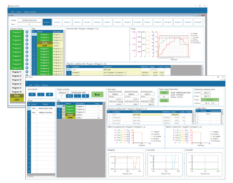
DigiCon is an application software that remotely controls Matsusada Precision's DC power supplies connected via LAN. The software can control multiple power supplies simultaneously or individually. -
- Power control for PRKT, PRT/PRTM, PBR/PBRM series
- Full remote control available
- Consists of "configuration software" and "operation software
- Linkage to digital multimeters, data loggers, and thermostatic chambers is possible.
- Easy operation with Graphical User Interface (GUI)
- Automatic Test Equipment (ATE)s can be built without programming knowledge.
- Real-time logging, graphing, and data storage
Dimensions
Download
If you are unable to download a file
Please try the following solution.
- Please press Ctrl+F5 to clear the cache of your web browser and try again.
- Please restart your web browser and log in again to try again.
- Please change your web browser to another browser and try again.
- Restart the computer and try again.
- Please try again on a different computer.

-
PRKT series Datasheet
Date: 2024-05-09 rev.13
PDF (3,532 KB)

-
DC POWER SUPPLIES SELECTION GUIDE
Date: 2023-12-06 rev.00
PDF (1,202 KB)

-
How to Use DC Power Supplies
Date: 2024-03-05 rev. 08
PDF (1,467 KB)

-
PRKT series Instruction Manual
Date: 2024-4-23 rev 0.6
PDF (2,100 KB)

-
Application package manual
Date: 2024-4-4 rev.2.3
PDF (2,227 KB)
The account registration is necessary for downloading

-
PRKT series Datasheet
Date: 2024-05-09 rev.13
PDF (3,532 KB)

-
DC POWER SUPPLIES SELECTION GUIDE
Date: 2023-12-06 rev.00
PDF (1,202 KB)

-
How to Use DC Power Supplies
Date: 2024-03-05 rev. 08
PDF (1,467 KB)

-
PRKT series Instruction Manual
Date: 2024-4-23 rev 0.6
PDF (2,100 KB)

-
Application package manual
Date: 2024-4-4 rev.2.3
PDF (2,227 KB)
In this website, we provide only the latest version of information including instruction manuals as of our products. Therefore, the newest versions of manuals on the website might be not same as the ones of products you purchased in the past.


