A comprehensive guide to DC power supply operation. Learn essential safety practices, load connection techniques, and installation tips to ensure reliable performance.
PROPER INSTALLATION OF POWER SUPPLY
Proper installation of the power supply is essential for your own personal safety and the longevity of the power supply.
Condition of installation
- Place the power supply's main body horizontally on a flat, smooth, stable surface.
- Do not use the power supply in an environment with excessive dust or corrosive gas.
- Be sure your power supply has proper ventilation. Do not install your power supply in an enclosed space where exhaust heat from the power supply's exhaust vents is blocked.
- Be sure to install your power supply in a dry area.
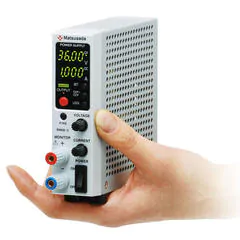
FAQ: Can I operate the benchtop power supply on its side?
How to install
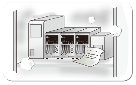
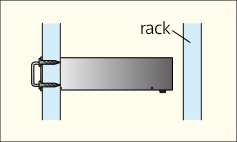
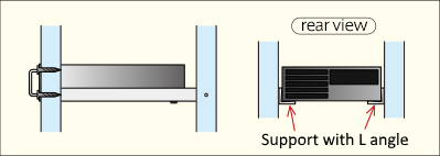
When mounting your power supply into a rack, please be certain that your power supply has adequate support. This can be done either with heavy-duty sliding rails or L-shaped support angles mounted below the power supply.
Not Good
Insufficient Support
Good
With Support Angles
Lifetime
The lifetime of a power supply can be reduced by up to 50% for every 10°C increase in ambient temperature.
(The power supply lifetime listed on the datasheet is based on an environmental temperature of about 20°C.)
STOP!
Environmental Conditions that Could Shorten the Lifetime of Your Power Supply
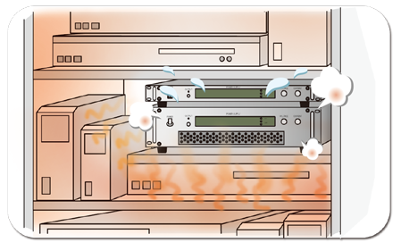
HEAT
Narrow spaces or enclosures tend to trap heat and can shorten the lifetime of your power supply. When air-inlets or exhaust vents are obstructed, the temperate inside the power supply increases dramatically and the lifetime of the power supply is reduced.
To ensure proper ventilation, maintain a clearance of at 4 inches (10 cm) at the air intake and 12 inches (30 cm) at the exhaust vents..
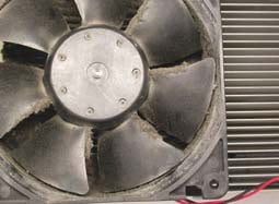
DUST
When a power supply is installed in a dusty environment or too close to the floor, it causes the accumulation of dust inside the power supply which results in deficient performance and a reduced lifetime.
CONNECTION OF LOAD
Your power supply's stability and ripple noise will be directly affected by its wiring and grounding.
• Use wires thick enough for your application. Use as short a length as possible.
• Select PVC electric wire (105°C) of the proper voltage rating
Current carrying capacity of electric wire, maximum length limited by maximum voltage compensation by remote sensing (0.5V/each way), has to be considered when connecting to the load. See the table below to determine the proper gauge of the wire.
| AWG | mm2 | Max. current [A] |
|---|---|---|
| 18 | 1.1 | 2 |
| 16 | 1.3 | 7 |
| 14 | 2.1 | 11 |
| 12 | 3.3 | 18 |
| 10 | 5.3 | 23 |
| 8 | 8.4 | 39 |
| 6 | 13 | 67 |
| 4 | 21 | 106 |
| 2 | 33 | 170 |
| 1 | 42 | 209 |
| 1/0 | 53 | 270 |
| 2/0 | 67 | 330 |
| 3/0 | 85 | 350 |
FAQ: Can we use multiple thin wires to connect the power supply to the load instead of thick wires?
• When connecting multiple loads in parallel, connect to each load
Good
Proper Connection

Not Good
Improper Connection

Loads further from the power supply (Loads 2 and 3) will experience a greater voltage drop. The ripple at those loads will also increase due to the current of each load.
• When connecting an inductive load, connect a protection diode across the load as shown in the diagram. This diode protects the power supply from counter-electromotive force (back EMF) generated when the output is turned off. Select a diode with a reverse voltage rating higher than the power supply's rated output voltage and a forward current rating sufficient for the maximum load current.

• Connecting a circuit that involves discharge or a short circuit may shorten the service life of the product and cause it to fail. When connecting to a circuit where discharge or short circuit may occur, install a protective resistance at the output.

CORRECT WAY TO MEASURE VOLTAGE
Accurate voltage application is critical for reliable system performance. However, wiring resistance can cause a voltage drop between the power supply and the load. DC power supplies feature a "remote sensing" function to detect and compensate for this voltage drop, ensuring the set voltage is accurately applied directly to the load.
How Remote Sensing Works
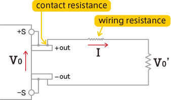
A voltage drop will occur when current flows over resistance of connectors or wires.
V0' = V0 - (Contact resistance + Wiring resistance) x I
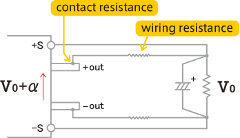
When connecting the remote sensing wires to the load to compensate for voltage drops, the power supply will increase its output voltage to compensate and maintain the set voltage at the load.
 Caution
Please check the following points of using remote sensing.
Caution
Please check the following points of using remote sensing.
- The impedance of the remote sensing input is high, making the sensing lines susceptible to external noise. Use twisted-pair or shielded wires for sensing connections to minimize noise interference.
- Placing an aluminum electrolytic capacitor at the sensing point often works better for stable behavior. The recommended capacitance of aluminum electrolytic capacitors is 0.1 to several hundred µF with a voltage rating of larger than the rated output voltage.
Additionally, in order to measure the voltage more precisely, a digital multimeter is available by connecting. The output voltage of the DC power supply should be adjusted until the desired voltage is measured at the load using a multimeter.
CONNECTION OF MULTIPLE POWER SUPPLIES TO OUTPUT
Series Operation
When connecting power supplies in series, ensure the total output voltage does not exceed the maximum output-to-ground voltage rating specified in the instruction manual for each unit.
When the master/slave function is to be used, follow the directions in the instruction manual.
Good
Connect as shown in the diagram above. Select diodes (D1, D2) with a reverse voltage rating greater than the power supply's output voltage and a forward current rating sufficient for the maximum load current.
Good
The connection diagram above may also be used. When controlling each power supply with an external voltage source, please note that the common potential for the control signal will differ for each unit. Isolated control signals are required to prevent short circuits.
Not Good
The connection depicted in the diagram above may not work. Due to the slight difference in the speed of each supply, current flowing from one power supply might cause a constant current mode in the other supply and cause a shutdown.
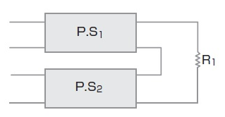
Parallel Operation
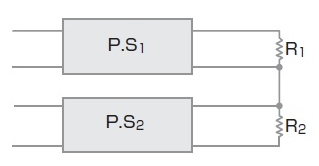
- When connecting multiple power supplies in parallel, balancing of the current is required because of the different output voltage between the power supplies.
- When the master/slave function is to be used, follow the directions in the instruction manual.
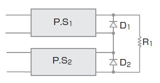
Good
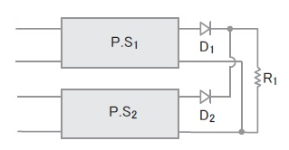
Connect as shown in the diagram to the left. Balance the current using diodes for D1 and D2 in the manner depicted. Consider the voltage rating of the diodes, the current, and the lower loss caused by heat.
FAQ: What precautions should be taken for the parallel connection of the power supplies?
Related Technical Articles
Recommended products
Matsusada Precision's high-performance DC power supplies