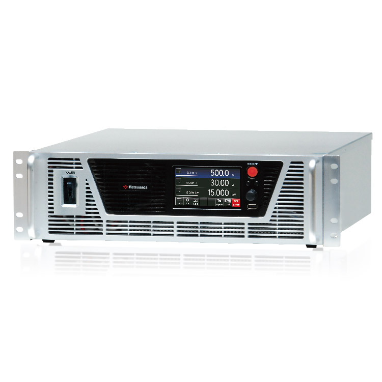
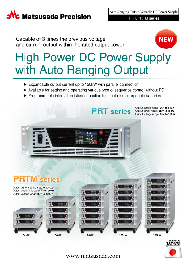
HIGH POWER DC POWER SUPPLY WITH AUTORANGING OUTPUT
Capable of 3 times the previous voltage and current output within the rated output power
- Voltage range: 80 V to 1500 V
- Current: 30 A to 510 A
- Power: 5 kW to 15 kW
- Variable internal resistance function
Wide-range voltage and current output up to 15 kW (3x coverage)
The PRT series is a programmable DC power supply equipped with a "Turbo" function, enabling autoranging output. It provides a voltage and current range three times wider than conventional fixed-range DC power supplies of the same power rating. This flexibility allows a single unit to cover a broad spectrum of applications, eliminating the need to source multiple power supplies with different ratings.
In addition to its wide-range capability, the PRT series features enhanced basic performance and reliability. Key features include a power factor correction (PFC) circuit with a power factor of 0.99, a high-visibility color display panel, and precision rotary encoders for intuitive operation.
FEATURES
- Equipped with a turbo function to achieve an auto-ranging of output.
- Expandable output current up to 150kW with parallel connection
- CV/CC priority setting function enables suppression of overshoot by setting the voltage/current increase sequence with the output ON
- Variable internal resistance function enables simple simulation of rechargeable batteries
- The sink current suppression reduces the reverse current flowing from the load to the unit in order to prevent a voltage drop on the load as the output is OFF or the set voltage is lowered.
- Low-noise switching method ideal for research & development
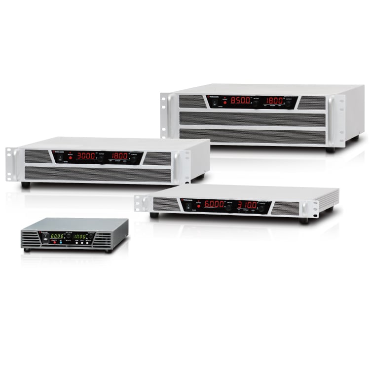
More Space Saving for Better Workplace
Introducing the extremely compact PRTM makes more effective use of your workspace. We have developed the smaller regeneration DC power supply for space saving aimed at installing other measuring tools, which makes effective use of the space at the workplace.
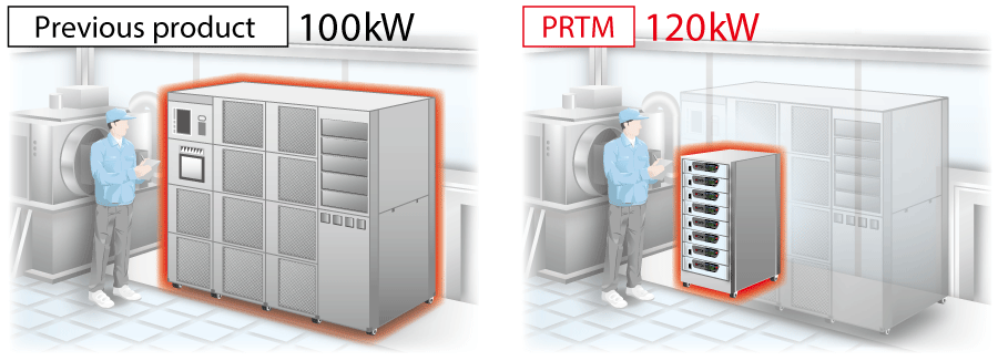
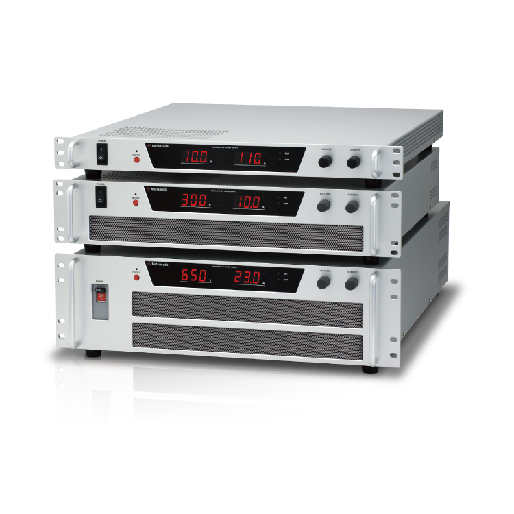
Compact Design and Thermal Management
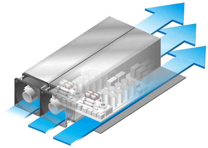
High-efficiency Circuitry
To minimize internal heat generation, the PRT series utilizes state-of-the-art semiconductor devices selected for their high efficiency. This design ensures stable performance while reducing the cooling load.
Optimized Airflow Design
The internal layout has been optimized to maximize cooling efficiency and minimize dead space. By refining the component arrangement and airflow path ("Air-through" design), we have achieved a high-density package with a height of just 133 mm (3U), significantly saving rack space without compromising thermal performance.
APPLICATIONS
-
Electric Vehicles (EVs), and Drones
Test and Evaluation of electronic components such as inverters, DC/DC converters, on-board chargers (OBC), DC motors, compressors, power relays, heaters, pumps, fuses, harnesses used in Battery Electric Vehicles (BEVs), Plug-in Hybrid Electric Vehicles (PHEVs), Hybrid Electric Vehicles (HEVs), and drones
-
Batteries
Charge and discharge cycle tests of high-voltage, high-power battery packs for lithium-ion batteries (LIB) such as Lithium iron phosphate (LFP) battery packs
-
Hydrogen and Ammonia production, Fuel cells
Development of hydrogen and ammonia production equipment (electrolysis, electrolytic synthesis, catalyst, and electrochemistry tests) and fuel cell technologies such as solid oxide fuel cell (SOFC) and solid oxide electrolysis cell (SOEC).
-
Power devices
Semiconductor Processing and burn-in of power semiconductors such as SiC, GaN, IGBT, MOSFETs, and laser diodes
-
Photovoltaic cells
Testing and evaluation of solar inverters (PV inverters), Hybrid inverters, junction boxes
-
Scientific Research, etc
In addition, the PRT/PRTM series is designed to meet a variety of DC power supply applications.
Models
| Model | Maximum output | Ripple (rms) | |||
|---|---|---|---|---|---|
| Voltage | Current | Power | Voltage | Current | |
| PRT80V170A5kW | 80 V | 170 A | 5 kW | 25 mV | 120 mA |
| PRT80V340A10kW | 340 A | 10 kW | 180 mA | ||
| PRT80V510A15kW | 510 A | 15 kW | 240 mA | ||
| PRT120V90A5kW | 120 V | 90 A | 5 kW | 40 mV | 180 mA |
| PRT120V180A10kW | 180 A | 10 kW | 200 mA | ||
| PRT120V270A15kW | 270 A | 15 kW | 240 mA | ||
| PRT200V70A5kW Coming soon | 200 V | 70 A | 5 kW | 80 mA | |
| PRT300V50A5kW | 300 V | 50 A | 5 kW | 40 mA | |
| PRT300V100A10kW | 100 A | 10 kW | 60 mA | ||
| PRT300V150A15kW | 150 A | 15 kW | 90 mA | ||
| PRT500V33A5kW | 500 V | 33 A | 5 kW | 70 mV | 16 mA |
| PRT500V66A10kW | 66 A | 10 kW | 32 mA | ||
| PRT500V100A15kW | 100 A | 15 kW | 48 mA | ||
| PRT850V53A15kW | 850 V | 53 A | 15 kW | 200 mV | 48 mA |
| PRT1000V30A10kW Coming soon | 1000 V | 30 A | 10 kW | 300 mV | 26 mA |
| PRT1500V30A15kW | 1500 V | 30 A | 15 kW | 350 mV | 26 mA |
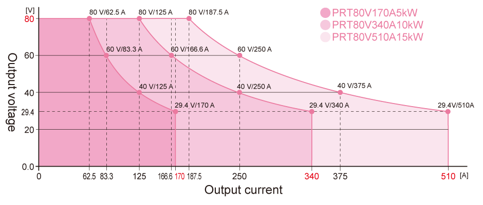
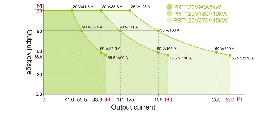
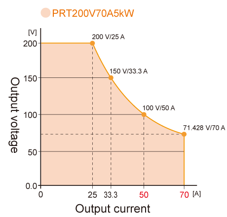
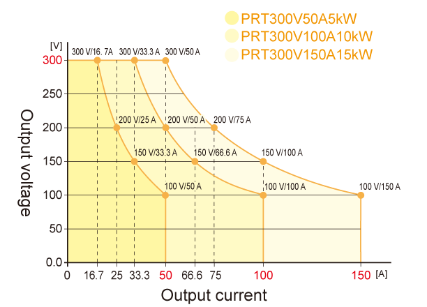
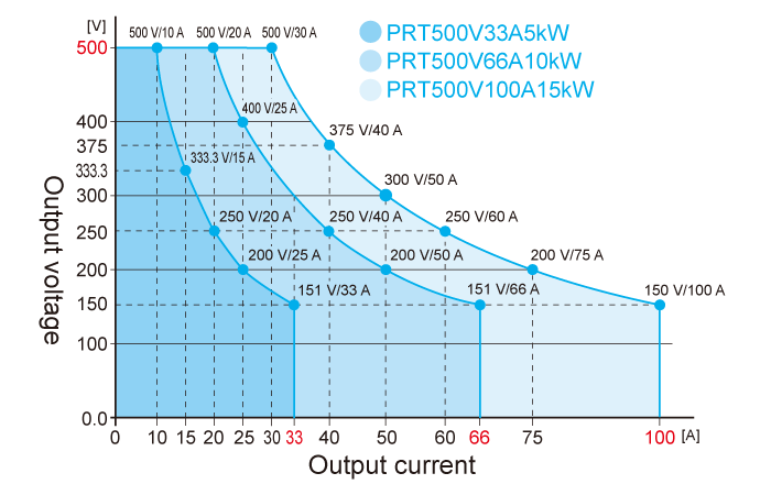
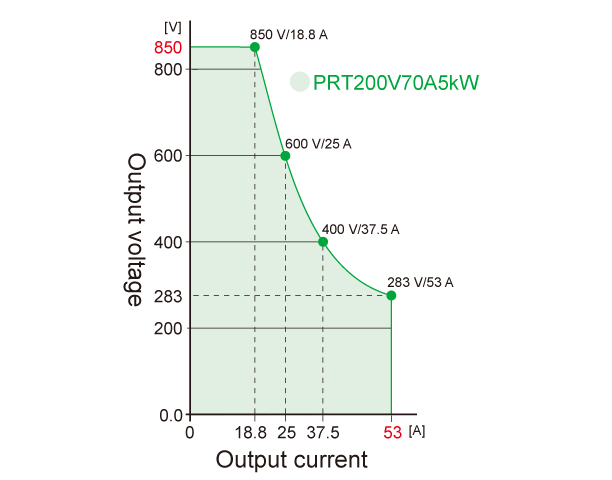
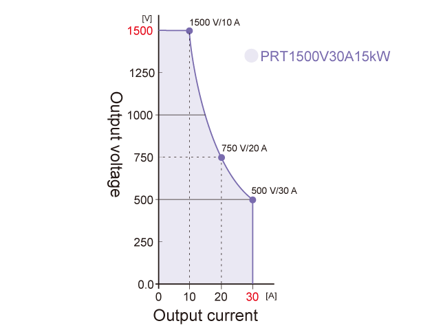
Output range graphs
With the turbo function, an auto-ranging of voltage and current output compared to conventional DC power supplies.

Functions
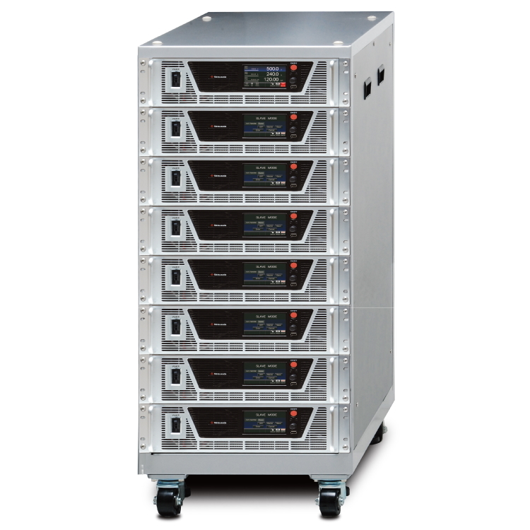
Scalable up to 150 kW with Master-Slave Control
Flexible Capacity Expansion
Output power can be easily expanded by connecting multiple units in parallel using the dedicated sharing cable and LAN cable. This allows users to scale the system capacity up to 150 kW to meet changing testing requirements.
(A "Master-slave control cable" set is available as an option.)
<Example> (1) 10 units of PRT80V510A (15 kW) in parallel → 80 V / 5100 A / 150 kW
- Connect up to 10 units (1 Master + 9 Slaves).
- In Master-slave operation, the total output current and voltage are displayed on the Master unit's panel. (Slave units do not display individual output values.)
Note: Make sure to use the same length of all the cables to connect each load and the main unit.
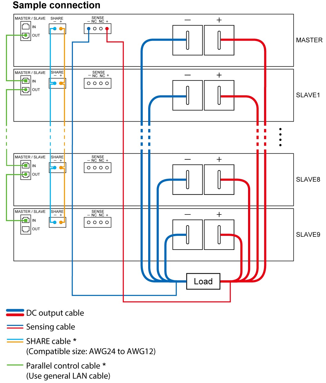
Master-slave control cable for PRT series is available as an optional accessory.
Application Operations with Front USB Port
No data logger or no always connected computer required
Shortening time of wiring and preparation, Suited for cycle tests in areas where computers are prohibited.

- Features:Built-in data logging
- Data logging captures the output data at the fastest interval of 0.1 seconds by inserting the USB memory stick. Also, with the dedicated software MLV, the log data is available in CSV format to output.
- Use in places where you cannot always connect a computer
- With the dedicated software MSS, you can save the sequence program data to the USB memory and load it from the front USB port. Thus, the program operation is available by the power supply only.
Functions with Front USB Port and Standard Attached Software
(1) Sequence program function: MSS (Matsusada Sequence Software)
- Easy to use for beginners
- MSS allows you to create sequence program data using the main unit or a computer with the dedicated software (MSS).
The software makes it easier and more convenient to create sequence program data. The created sequence program data can be saved to USB memory, and up to 1,024 steps of the sequence program can be loaded.

(2) MLV (Matsusada Log Viewer): Graphical display of operation logs
- Quickly display operation logs in graphs
- Using the Matsusada Log Viewer (MLV), you can read log files saved on USB memory, etc., and quickly display them in graphs. This allows you to easily find abnormalities during operation.
- CSV file export for operation log data
- You can also select export items from the operation log and save them in CSV format. Then, you can load the CSV log data in a spreadsheet to help you create reports.
-
Display items
- Elapsed time
- CC/CV mode
- Output value (voltage, current, power)
- Status
- Other information
The operation logging function is possible during sequence program operation, local control, and remote control. A USB memory is required to save the operation log.

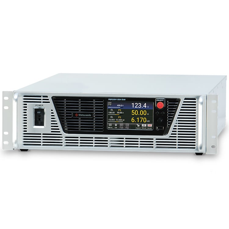
Large Color Touch Panel
PRT/PRTM series comes with a large color touch panel, realizing its operability and visibility improvement.

- Easy setting of output voltage, current, power, and other parameters !
- Simple setting to complex sequence program !
- New feature with more selectable error detections !
- Equally available in a conventional configuration with the setting dial
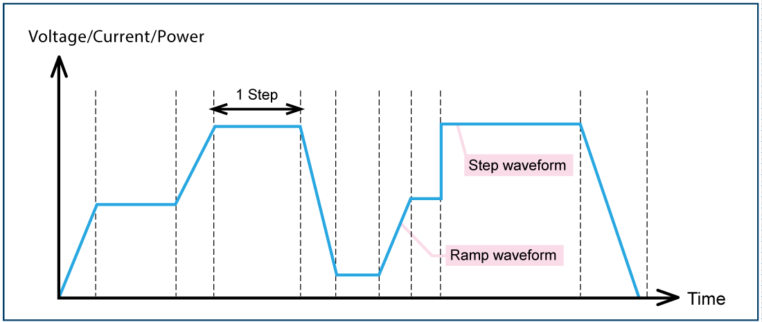
Sequence Programming Function
The sequence programming function allows the programming of parameters such as step time, step amplitude, ramp, CV/CC mode, sequence program end-setting, step jump, and jump count by simply operating on the front panel. This option enables you to generate customized original waveforms, and you can use a great variety of applications including testing evaluation, and verification.
- Step setting time 0.0 to 3,600 s
- For one program, a maximum of 1,024 steps can be configured and saved.
- CV/CC mode can be set for each program.
- Repetition frequency: infinity, or 1 to 999 Program as Image
Program as image
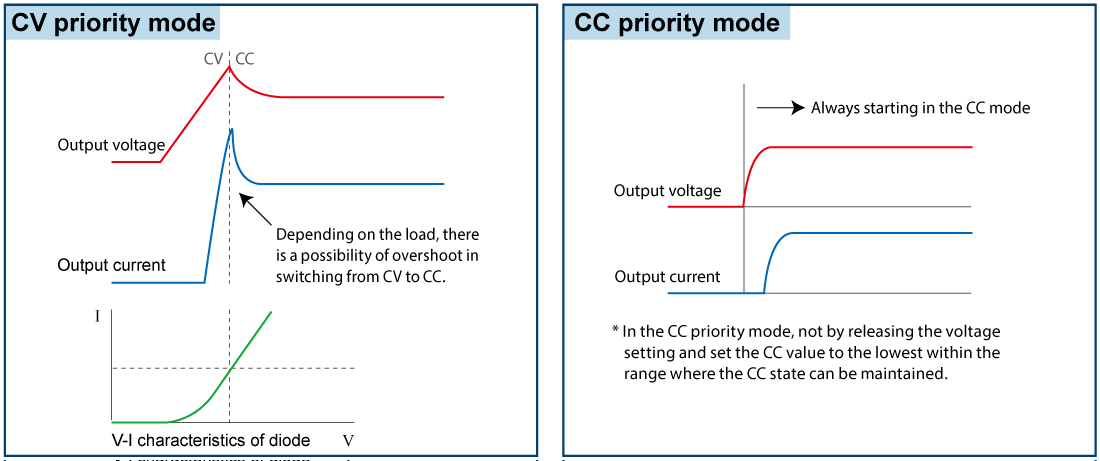
CV/CC Priority Setting Function
CV (constant voltage) priority/CC (constant current) priority mode can be selected and set. As is the case with diodes, a load tends to suddenly change the resistance at certain points. When the device is started in CV mode, the current will be momentarily overshot. In the PRT series, select the CC priority mode to suppress the occurrence of overshoot. The function can reduce the risk of damaging expensive loads such as high-power laser diodes.
* In the CC priority mode, do not release the voltage setting and set the CC value to the lowest within the range where the CC state can be maintained.
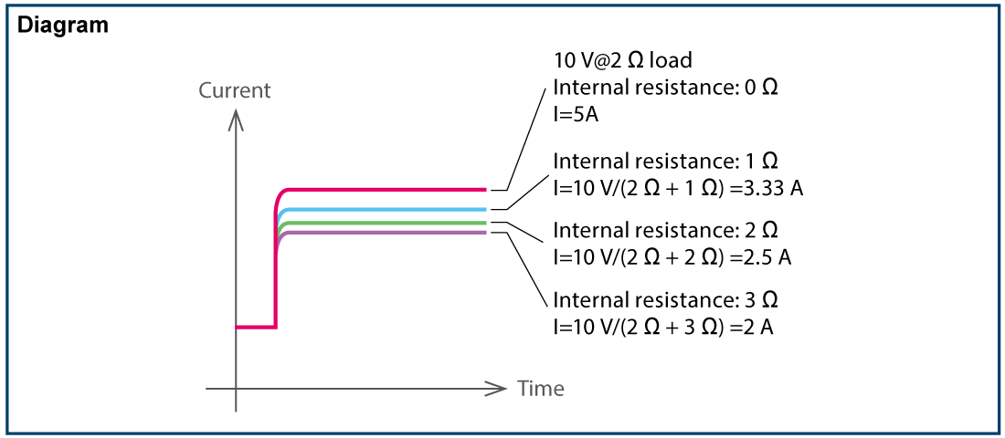
Variable Internal Resistance Function (in CV Mode)
Set the internal resistance to any value to generate a voltage drop when the load current flows.
Batteries, photovoltaic cells, and fuel cells can be simulated.
(The setting range of the internal resistance value is from 0 Ω to the rated voltage/rated current.)
Preset Memory Function
With the preset memory function, the preset values are automatically saved when the power turns off.
Furthermore, up to three different voltage, current, and power settings are also memorized respectively.
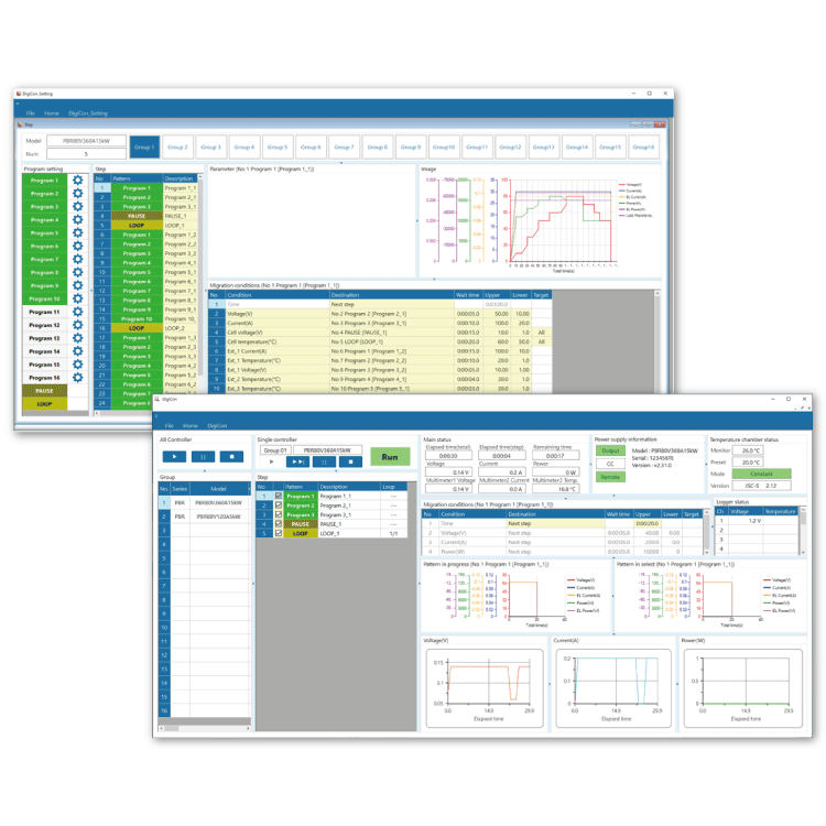
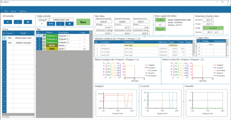
Remote Control Software (Additional Accessory): DigiCon series
DigiCon is an application package that remotely controls Matsusada Precision's DC power supplies connected via LAN.
The software can control multiple power supplies simultaneously or individually.
- Power control for PRKT, PRT/PRTM, PBR/PBRM, P4KF, PKTS, HARS series
- Full remote control available
- Consists of "configuration software" and "operation software
- Linkage to digital multimeters, data loggers, and thermostatic chambers is possible.
- Easy operation with Graphical User Interface (GUI)
- Automatic Test Equipment (ATE) can be built without programming knowledge.
- Real-time logging, graphing, and data storage
Link with digital multimeters, data loggers, and thermostatic chambers is possible.
Program transitions can be made in response to external conditions by linking with measuring instruments such as digital multimeters and data loggers, as well as thermostatic chambers.
This advanced function allows the program to transition to the next step when the end condition of the instrument is met without waiting for a set time, or to safely terminate the program if a problem occurs during operation.
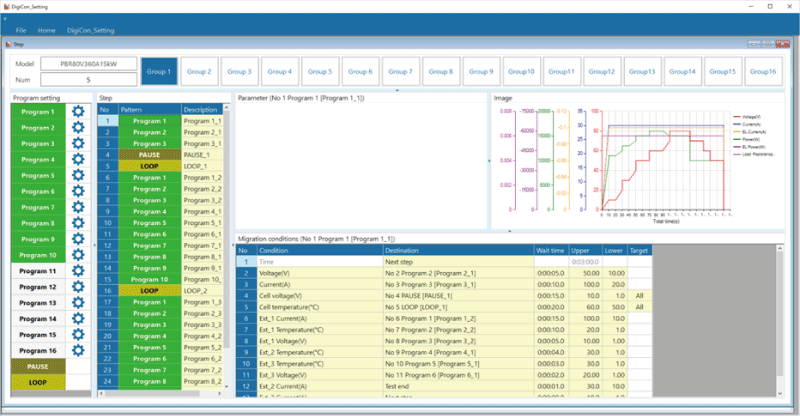
Easy operation enables speedy construction of Automatic Test Equipment (ATE)
Graphical user interface, including graphical display of set values, allows easy operation.
Automatic Test Equipment (ATE) and inspection systems can be built without programming knowledge.
It can be used in many fields and applications, such as long-term reliability testing of electronic equipment and devices in the automotive, home appliance, and medical fields.
Sink current prevention function
The function is suitable for supplying power to loads with capacities like batteries and capacitors. It reduces the reverse current flowing from the load to the unit in order to prevent a voltage drop on the load as the output is OFF or the set voltage is lowered.

Note: Reverse current cannot be controlled and stabilized. In order to protect the power supply unit, connect a dummy resistor or reverse current prevention diode if the load of the reverse voltage is equal to or higher than the rated voltage (inductive loads, regenerative motors, etc.).
Two-mode Lock Function
The locking is selectable from two setting modes: One is "Full LOCK" to lock all front panel operations, and the other is "Normal LOCK" to lock all operations except the ON/OFF switch.
The function is so user-friendly that the "Full LOCK" mode is provided to ensure the prevention of erroneous operation, and the "Normal LOCK" function facilitates the emergency stop while preventing erroneous operation. Emergency stop operation using the POWER ON/OFF switch is possible in either mode.

Password Function New
In this function, to cancel the two-mode lock function, input a 4-digit PIN code. (Enable/Disable is selectable.)

Secure Analog Remote Control
The external analog remote control of voltage/current/power is isolated from the output of the power supply as standard.
When controlling/monitoring multiple power supplies, you can use the product more securely as the external analog remote control has a chassis (ground) potential.
External Analog Control
- External output ON/OFF
- Remote sensing
- Remote/Local mode setting
- Status output
- Output monitor
- Output control
(Voltage, Current, Power, Overvoltage protection, Overcurrent protection, Overpower protection)
Residual Voltage Detection LED
- Use for checking residual voltage
- The LED on the rear panel blinks when there is voltage remaining on the DC output terminal in output or at output off. it is useful for reference to check if the voltage remains. Be sure to check the voltage before the operation of the unit.

Constant Power Control Function (CP Mode)

In addition to Constant Voltage control (CV mode) and Constant Current control (CC mode), Constant Power Control (CP mode) is provided.
With CP mode, a constant power supply is provided depending on loads, such as resistors (heaters) whose resistance changes with temperature. It is available without monitoring voltage/current or attaching external control devices (temperature regulators).
Specifications
- Input voltage
-
200 to 240 Vac, 50/60 Hz, Single-phase
200 to 240 Vac, 50/60 Hz, Three-phase
380 to 440 Vac, 50/60 Hz, Three-phase (Option) - Output voltage control
-
[Local] Rotary encoder on front panel
[Analog remote] External control voltage 0 to 10 Vdc
[Digital remote] Command - Output current control
-
[Local] Rotary encoder on front panel
[Analog remote] External control voltage 0 to 10 Vdc
[Digital remote] Command - Output power control
-
[Local] Rotary encoder on front panel
[Analog remote] External control voltage 0 to 10 Vdc
[Digital remote] Command
For details, download the datasheet below.
FAQs
- How should I choose a circuit breaker for a high-power DC power supply?
- Can we use multiple thin wires to connect the power supply to the load instead of thick wires?
- We are concerned that the output terminal is equipped with a metal cover. Is it safe to use it as it is?
- What precautions should be taken for parallel connection of the power supplies?
- Do you have any tips for extending the service life of power supplies?
Options
- -LCa *
-
CAN interface port
Using CAN communications, output controlling and operation status monitoring of these devices can be performed.
- -LGob *
-
Optical interface port
- -LGob: Optical interface + optical cable 2 meters
- -LGob(Fc5): Optical interface + optical cable 5 meters
- -LGob(Fc10): Optical interface + optical cable 10 meters
- -LGob(Fc20): Optical interface + optical cable 20 meters
- -LGob(Fc40): Optical interface + optical cable 40 meters
The optical communication adapter at the control side should be purchased separately.- for LAN: CO-E32
- for USB: USB-OPT
- for RS-232C: CO-OPT2-25, CO-OPT2-9
- for RS-485: CO-OPT4-25
- for GPIB: CO-G32 (Scheduled for discontinuation in December 2028)
The unit is remotely controlled by isolating with optical communication. As complete isolation is provided by means of optical fiber, this enables advanced prevention of erroneous operation involved with transient phenomenon caused by surges, inductive lightning, external noise, etc.
- -LRs *
-
RS-232C/RS-485 interface port
Using RS-232C/RS-485 communications, output controlling and operation status monitoring of the devices can be provided.
- -L(400V)
-
Rated input for three-phase 380 Vac to 440 Vac 3 x 28 A (@400 V)
As for 15kW models, the rated voltage of the power grid is 380 to 440 Vac, 3x28 A (@400 V), three-phase, 50/60 Hz.
(The option is available only for models with 15 kW output.)
* Selecting each individual option simultaneously in -LCa, -LGob, and -LRs is not allowed.
How to Order
When ordering, add Option No. to Model No. in alphabetical order followed by the input voltage.
Example: PRT80V510A15kW-LGob (Fc10), PRT850V53A15kW-LCa(400V)
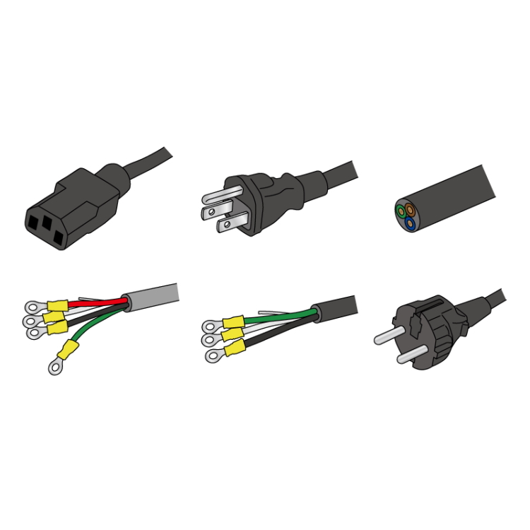
ADDITIONAL ACCESSORIES
- AC input cable
-
Sold separately CABLE TYPE14 
600 V/58 A 10 meters Sold separately
[200 Vac to 240 Vac single-phase inut]CABLE TYPE15 
600 V/58 A 10 meters Sold separately
[380 Vac to 440 Vac three-phase inut]CABLE TYPE16 
600 V/58 A 10 meters Sold separately
[200 Vac to 240 Vac single-phase]CABLE TYPE17 

250 V/33 A 10 meters In accordance with the local electrical code, there might be a possibility that a breaker is required between the main unit and the power supply system. If the PRT series will be used in Europe, be sure to contact our sales representatives.
- Master-slave control cable
-
This cable set includes a [share cable] (photo on the right) with the share terminals, and the [parallel control cable] (LAN cable). Please choose from the table below according to the number of parallel connection units.
Model name Units number Included in the set Share cable Parallel control cable PRT-MS2 cable 2 1.5 meters × 1 1.5 meters × 1 PRT-MS3 cable 3 3.0 meters × 1 1.5 meters × 2 PRT-MS4 cable 4 4.5 meters × 1 1.5 meters × 3 PRT-MS5 cable 5 6.0 meters × 1 1.5 meters × 4 PRT-MS6 cable 6 7.5 meters × 1 1.5 meters × 5 PRT-MS7 cable 7 9.0 meters × 1 1.5 meters × 6 PRT-MS8 cable 8 10.5 meters × 1 1.5 meters × 7 PRT-MS9 cable 9 12.0 meters × 1 1.5 meters × 8 PRT-MS10 cable 10 13.5 meters × 1 1.5 meters × 9 <Example> The cable for connecting 3 PRT 
- Application software
-
DigiCon-PRT: Remote control, Test workflow design, and Data logging
DigiCon is an application software that remotely controls Matsusada Precision's DC power supplies connected via LAN. The software can control multiple power supplies simultaneously or individually. -
For details, Refer to "Remote Control Software".
- Power control for PRKT, PRT/PRTM, PBR/PBRM, P4KF, PKTS, HARS series
- Full remote control available
- Consists of "configuration software" and "operation software
- Linkage to digital multimeters, data loggers, and thermostatic chambers is possible.
- Easy operation with Graphical User Interface (GUI)
- Automatic Test Equipment (ATE) can be built without programming knowledge.
- Real-time logging, graphing, and data storage

Dimensions
Download
If you are unable to download a file
Please try the following solution.
- Please press Ctrl+F5 to clear the cache of your web browser and try again.
- Please restart your web browser and log in again to try again.
- Please change your web browser to another browser and try again.
- Restart the computer and try again.
- Please try again on a different computer.
-
PRT series Datasheet
Date: 2026-03-16 rev 25
PDF (6,458 KB)
-
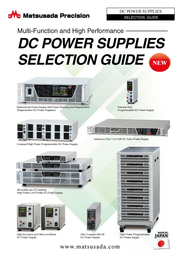
DC POWER SUPPLIES SELECTION GUIDE
Date: 2026-03-26 rev 03
PDF (4,921 KB)

-
How to Use DC Power Supplies
Date: 2026-04-16 rev 10
PDF (1,335 KB)

-
PRT series Basic Instruction Manual (Both Japanese and English)
Date: 2021-04-22 rev 1.3
PDF (937 KB)
-
PRT series Instruction Manual
Date: 2025-12-04 rev 2.3
PDF (1,966 KB)
-
Application package manual
Date: 2025-11-20 rev 2.4
PDF (2,067 KB)
-
DigiCon Instruction Manual
Date: 2025-03-25 rev 0.2
PDF (4,541 KB)
-
Command List (PRT, PRKT, PBR, PKTS series)
Date: 2025-03-19 rev 0.3
PDF (918 KB)

-
PRT series Outline Drawing (DXF, PDF)
Date: 2020-06-01
zip (2,064 KB)
Login Required
-
PRT series Datasheet
Date: 2026-03-16 rev 25
PDF (6,458 KB)
-
DC POWER SUPPLIES SELECTION GUIDE
Date: 2026-03-26 rev 03
PDF (4,921 KB)
-
How to Use DC Power Supplies
Date: 2026-04-16 rev 10
PDF (1,335 KB)
-
PRT series Basic Instruction Manual (Both Japanese and English)
Date: 2021-04-22 rev 1.3
PDF (937 KB)
-
PRT series Instruction Manual
Date: 2025-12-04 rev 2.3
PDF (1,966 KB)
-
Application package manual
Date: 2025-11-20 rev 2.4
PDF (2,067 KB)
-
DigiCon Instruction Manual
Date: 2025-03-25 rev 0.2
PDF (4,541 KB)
-
Command List (PRT, PRKT, PBR, PKTS series)
Date: 2025-03-19 rev 0.3
PDF (918 KB)
-
PRT series Outline Drawing (DXF, PDF)
Date: 2020-06-01
zip (2,064 KB)
On this website, we provide only the latest versions of information and instruction manuals for our products. Therefore, the newest versions of manuals on the website may differ from those that came with products you purchased in the past.