


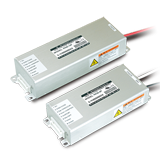
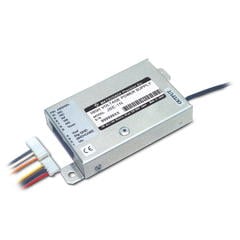
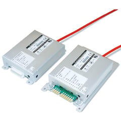
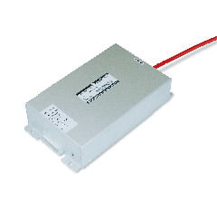
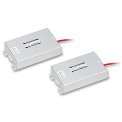
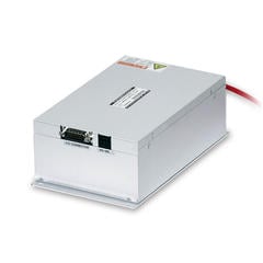
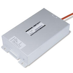
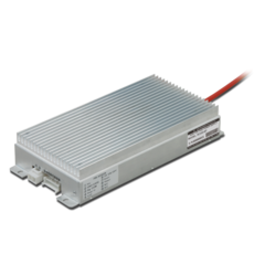
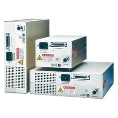
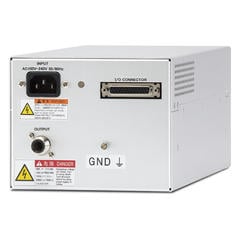
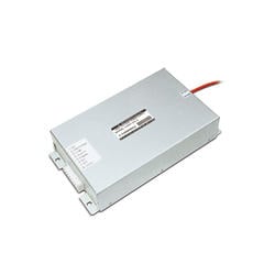
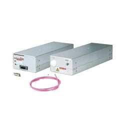
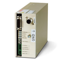
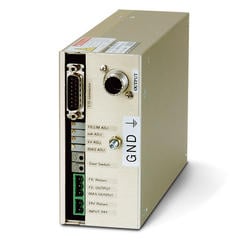
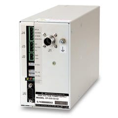
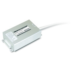
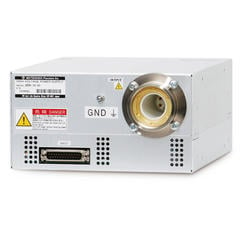
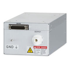
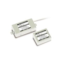
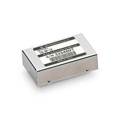
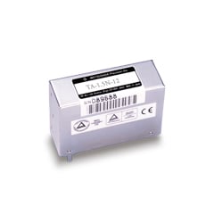
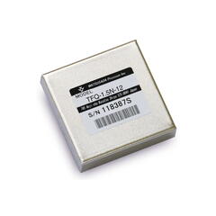
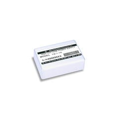
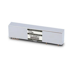
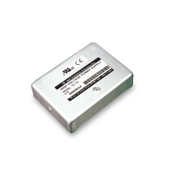
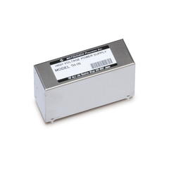
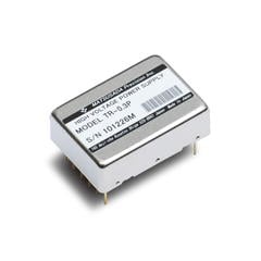
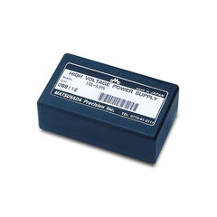
Module (Chassis mount) Type
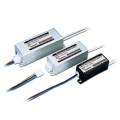

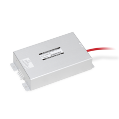
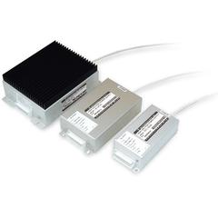
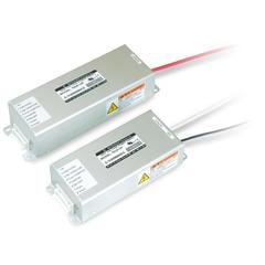
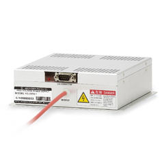

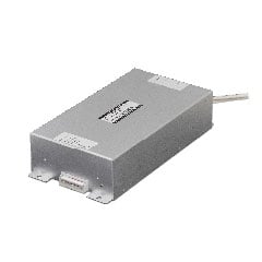
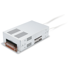
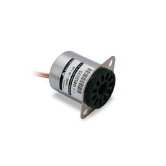
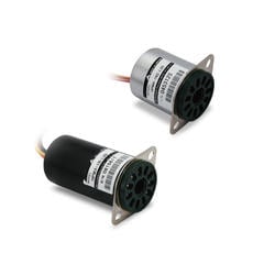
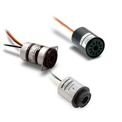

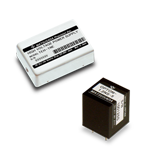
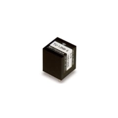
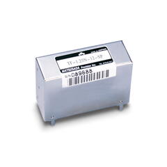
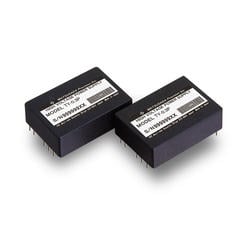
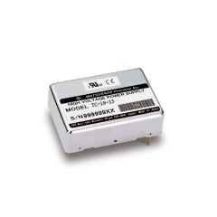
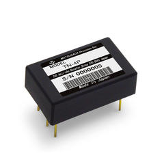
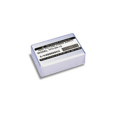
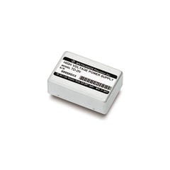
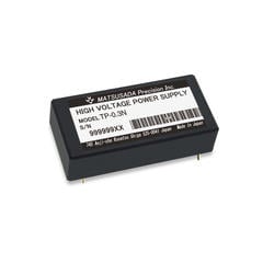
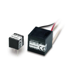
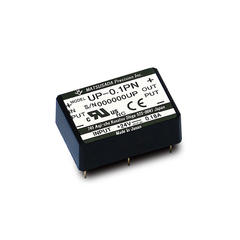
PCB mount (On-board) Type
When selecting high voltage power supplies Please read before operation
- While the power supplies in this datasheet are designed and manufactured with high voltage safety in mind, always follow the operating instructions provided and ensure the power supplies are properly earthed (grounded) for safe operation.
- Unless they are input/output proportional type models rated 6kV or below, the power supplies in this datasheet are designed to be operated at ground potential. Models 6 kV and below of input/output proportional type must be operated within the dielectric voltage specified in the datasheet.
- External high voltage applied to power supplies in the datasheet can cause power supply failure. Protection circuits are there to protect power supplies from failures, and not to protect loads or devices connected to power supplies. If necessary, implement appropriate protective measures for devices connected to these high voltage power supplies.
Technical Note Input/output proportional type/Regulated high performance modules
The values of the specifications in the datasheet refer to values at maximum rating output (full scale) after 30 minutes warm-up unless otherwise specified.
Scope of application of specifications
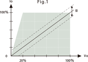
For regulated modules, these specifications (Ripple, Regulation, Voltage setting accuracy, Temperature coefficient) apply under the conditions shown in Fig. 1.
For input/output proportional types, the horizontal axis is limited by the output voltage range (refer to the specific product's specification page).
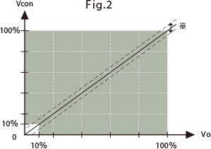
Linearity: Applies from 10% to 100% of the output voltage, as illustrated in Fig. 2.
Troubleshooting and Common Issues
High-voltage power supplies function as part of a larger system. Performance issues often stem from incorrect connections or load mismatching rather than unit failure. Please review the following checklist before returning the unit for service.
| Symptom | Possible Cause | Checkpoint / Action |
|---|---|---|
| No output voltage | Incorrect connection (especially input side) | Verify all connections. |
| Output voltage does not increase | Insufficient input current | Test with a power source that meets the current requirements. |
| Input power supply has insufficient current capacity | ||
| Overcurrent condition | Check if voltage increases when no load is connected. | |
| Output wire is broken | Check continuity of the wiring. | |
| Impedance of the monitoring voltmeter is too low | Use a voltmeter with input impedance >10 MΩ. | |
| Voltage monitor reading is incorrect | Impedance of the voltmeter used to measure the voltage monitor is inappropriate (too low) | Use a voltmeter with input impedance >10 MΩ. |
| Current monitor reading is incorrect Offset detected |
Measure with ammeter | |
| Impedance of monitoring voltmeter is incorrect | ||
| Offset voltage requires cancellation | Adjust offset by referring to the example circuits in the datasheet. | |
| Audible high-frequency noise | Overcurrent condition | Check if the noise persists with the rated load or no load. |
| Ripple noise exceeds datasheet specifications | External noise interference | Test with a low-noise input power supply. |
| Shield the input wiring. | ||
| Ensure single-point grounding is implemented. | ||
| Isolate from noise sources. |