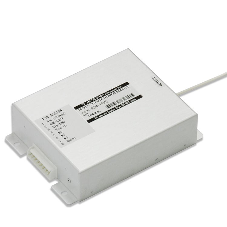
PIEZO DRIVER MODULE
- High voltage output models up to 1 kV
- Output voltage monitor available as standard
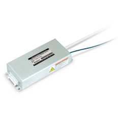
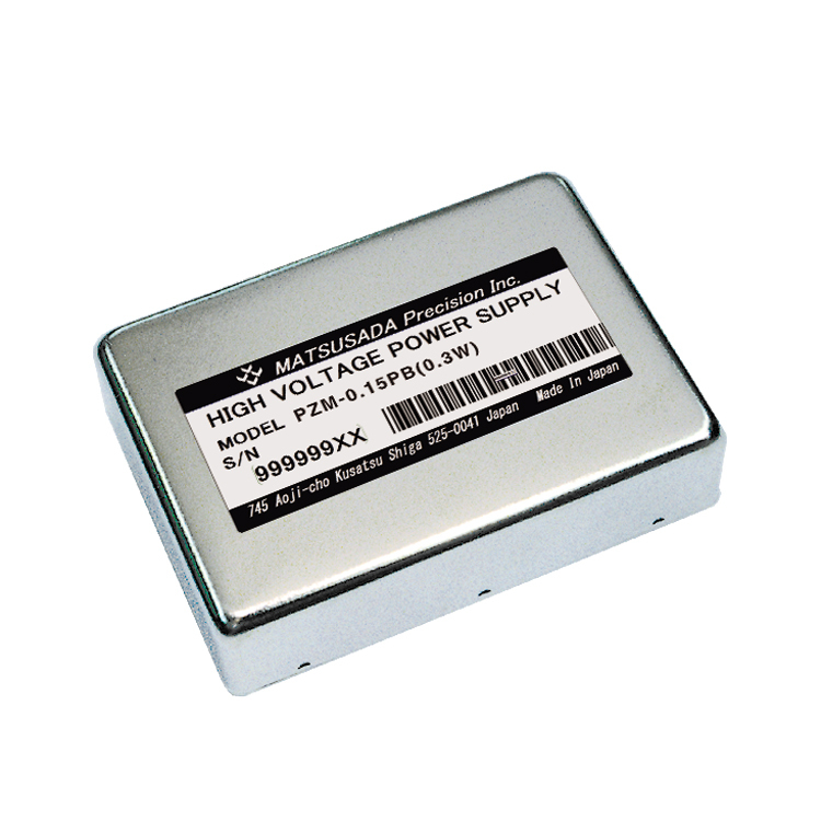
Compact Piezo Driver Modules
The PZM Series consists of compact high-voltage power supply modules designed exclusively for driving piezoelectric elements. With output voltage controlled via an external signal, these modules are optimized for precision applications. The series is equipped with comprehensive protection circuits to prevent damage to the piezoelectric load, ensuring high reliability in demanding environments.
FEATURES AND BENEFITS
- Ideal for OEM integration: Compact module design fits easily into systems.
- High performance: Low ripple and high stability output.
- Safety features: Equipped with overcurrent protection circuits.
- Standard monitoring: Output voltage monitor included.
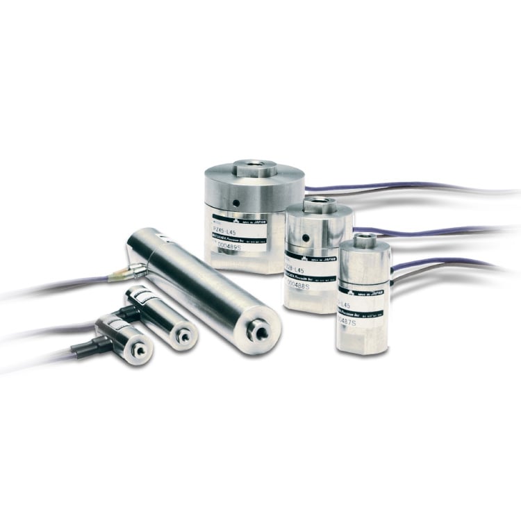
APPLICATIONS
Models
| Model | Output voltage [Vdc] | Output current | Response speed | Output resistance |
||||
|---|---|---|---|---|---|---|---|---|
| Rated Imean *1 | Peak Ip ≤ 10 ms |
Sine wave (-3 dB) | Rising time *2 | |||||
| at Resistive load | 1 µF load | △V = 100 V | 0 to Max. voltage | |||||
| PZM-0.1P(A) | 0 to 100 V | 30 mA | 42 mA | DC to 10 kHz | DC to 130 Hz | 2.4 ms | 2.4 ms | 51 Ω |
| PZM-0.15P(A) | 0 to 150 V | 20 mA | 28 mA | DC to 6 kHz | DC to 60 Hz | 3.6 ms | 5.4 ms | 100 Ω |
| PZM-0.3P(A) | 0 to 300 V | 10 mA | 14 mA | DC to 3 kHz | DC to 15 Hz | 7.2 ms | 30 ms | 200 Ω |
| PZM-0.6P(A) | 0 to 600 V | 6.6 mA | 9 mA | DC to 2 kHz | DC to 5 Hz | 15.5 ms | 94 ms | 300 Ω |
| PZM-1P(A) | 0 to 1000 V | 3.3 mA | 4.5 mA | DC to 2 kHz | DC to 1.5 Hz | 31 ms | 311 ms | 500 Ω |
- The output current for DC is 50% of the rated current.
- Approximate value at 1 µF load. Calculated based on the peak output current (available for up to 10 ms) using Tr = C × Vp-p / Ip. If the calculated Tr exceeds the 10 ms peak current duration, the rise time is calculated using the rated average current (Imean).
Specifications
- Input voltage
- 24 Vdc ±5% (22.8 to 25.2 Vdc)
- Output voltage control
- External control voltage 0 to +10 Vdc
Accessory
Additional Accessory
- CN8R
- Assembled input connector with 0.25 meters flying leads
Diagram
Connection diagram
Dimensions
120 x 100 x 35mm (4.72" x 3.94" x 1.38")
For details, download the datasheet below.
Download
If you are unable to download a file
Please try the following solution.
- Please press Ctrl+F5 to clear the cache of your web browser and try again.
- Please restart your web browser and log in again to try again.
- Please change your web browser to another browser and try again.
- Restart the computer and try again.
- Please try again on a different computer.
-
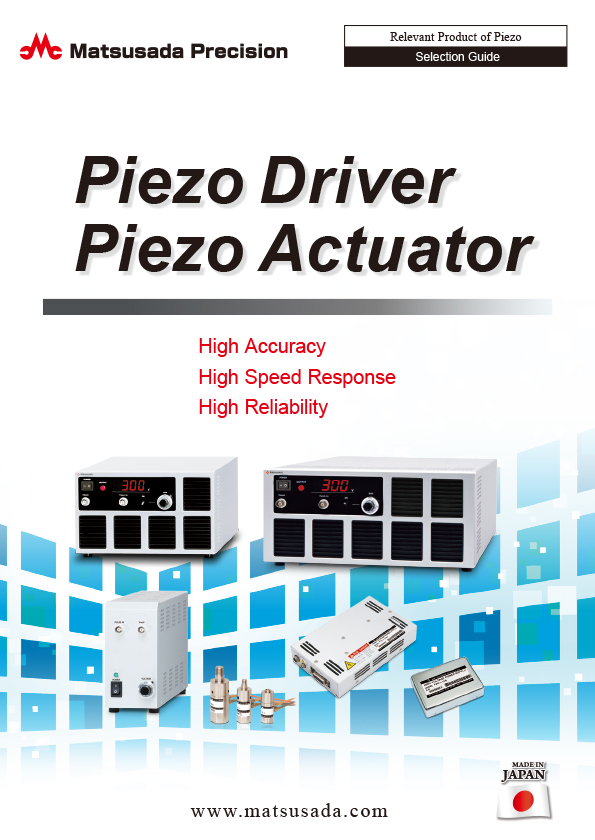
Piezoelectric products Selection Guide
Date: 2025-12-05 rev 25
PDF (4,427 KB)
-
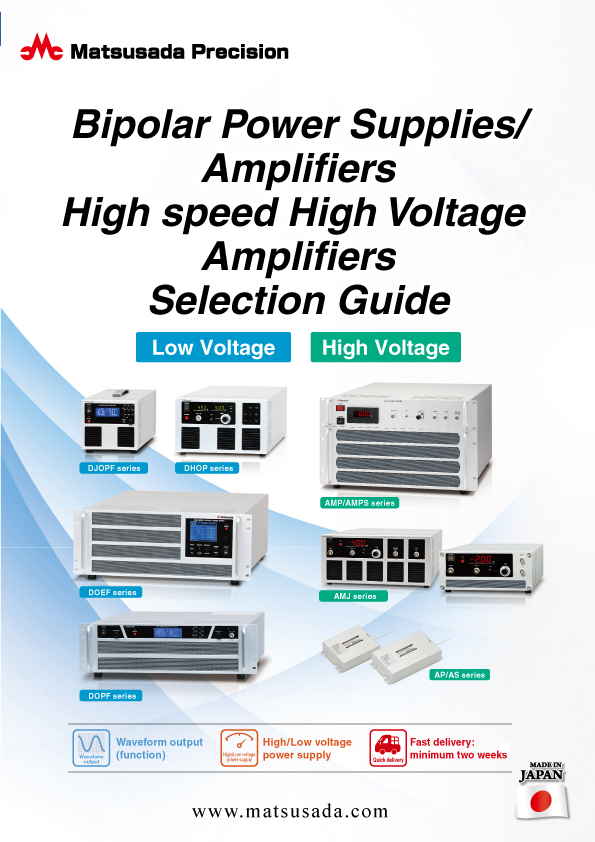
Bipolar Power Supplies/Amplifiers Selection Guide
Date: 2023-10-17 rev.03
PDF (6,310 KB)

-
Safety and Usage of High voltage Power supply
Date: 2025-09-08 rev 04
PDF (602 KB)
Login Required
-
Piezoelectric products Selection Guide
Date: 2025-12-05 rev 25
PDF (4,427 KB)
-
Bipolar Power Supplies/Amplifiers Selection Guide
Date: 2023-10-17 rev.03
PDF (6,310 KB)
-
Safety and Usage of High voltage Power supply
Date: 2025-09-08 rev 04
PDF (602 KB)
On this website, we provide only the latest versions of information and instruction manuals for our products. Therefore, the newest versions of manuals on the website may differ from those that came with products you purchased in the past.
Related Technical Articles
- About Piezo Drivers
- Amplifier Basics: Principles, Operation, and Key Considerations
- Safety and Usage of High Voltage Power Supply
- What are Piezoelectric Devices? Principles, Structure, and Applications Explained
- Proper Usage Guidelines for Piezoelectric Actuators
- What is a Piezo Actuator? (Basic Knowledge)