


Selection chart of High Voltage Amplifiers
High Voltage Amplifiers
Our lineup ranges from ultra-fast response models with slew rates up to 1,200 V/µs to compact modules designed for system integration. These amplifiers can generate high-voltage outputs in various waveforms, including sine, triangle, sawtooth, and square waves.
| Series |
AMJ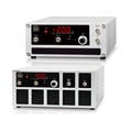
|
AMS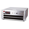
|
AMT
|
AMP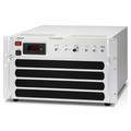
|
AMPS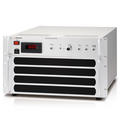
|
COR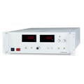
|
HOPH
|
AP
|
AS
|
|
|---|---|---|---|---|---|---|---|---|---|---|
| Output Power | 20 to 40 W | 20 W, 30 W | 60 W, 100 W | 100 to 1200 W | 400 to 1200 W | 20 W | 5 W | 3 to 10 W | 3 to 10 W | |
| Frequency response (Fastest model bandwidth) |
DC to 75 kHz (-3 dB) |
DC to 2 kHz (-3 dB) |
DC to 100 kHz (-3 dB) |
DC to 40 kHz (-3 dB) |
DC to 200 kHz (-1 dB) |
DC to 1 kHz (-3 dB) |
DC to 2 kHz (-3 dB) |
DC to 3 kHz (-3 dB) |
DC to 25 kHz (-3 dB) |
|
| Slew rate | 150 V/µs | 30 V/µs | 250 V/µs, 360V/µs | Up to 700 V/µs | Up to 1200 V/µs | 30 V/µs | 40 V/µs | - | 12 V/µs or more | |
| Output Voltage | 0.3 kV | ±0.3 kV | ±0.3 kV | |||||||
| 0.5 kV | ±0.5 kV | |||||||||
| 0.6 kV | ±0.6 kV | ±0.6 kV | ±0.6 kV | ±0.6 kV | ±0.6 kV | |||||
| 1 kV | ±1 kV | ±1 kV | ±1 kV | ±1 kV | ±1 kV | |||||
| 1.5 kV | ±1.5 kV | ±1.5 kV | ±1.5 kV | |||||||
| 2 kV | ±2 kV | ±2 kV | ±2 kV | |||||||
| 3 kV | ±3 kV | ±3 kV | ±3 kV | |||||||
| 4 kV | ±4 kV | |||||||||
| 5 kV | ±5 kV | ±5 kV | ±5 kV | ±5 kV | ±5 kV | 5 kV (Unipolar only) |
||||
| 10 kV | ±10 kV | ±10 kV | ±10 kV | ±10 kV | ±10 kV | 10 kV (Unipolar only) |
||||
| 20 kV | ±20 kV | ±20 kV | ||||||||
| 30 kV | ±30 kV | ±30 kV | ||||||||
| 40 kV | ±40 kV | |||||||||
| Features | Wave form | Various types of output waveforms | Various types of output waveforms according to the input wave | Various types of output waveforms according to the input wave | Desired output waveform reference to the input waveform. | Desired output waveform reference to the input waveform. | Desired output waveform reference to the input waveform. | |||
| DC bias function | DC bias function | DC bias function | DC bias function | |||||||
| DC output voltage monitor | DC output voltage monitor, 3.5-digit digital meter | DC output voltage monitor, 3.5-digit digital meter | DC output voltage monitor, 3.5-digit digital meter | |||||||
| Other | The demand for evaluation of higher voltage solar panel | Three functions of CC, CV, and HV amplifier in one unit | All-Solid-State | All-Solid-State | ||||||
| Return current terminal is standard and best for corona current control | ||||||||||
| Ripple | Less than 0.1% | 0.1% p-p or less | 0.02% + 1 Vp-p or less | Less than 0.02% + 1 Vp-p | Less than 0.02% + 0.5 Vp-p | 0.1% p-p or less | ≦10 Vrms | 0.025% rms or less | 0.025% rms or less | |
| Applications | Electro photography process | Electro photography process | Electro photography process | Electro photography process | Electro photography process | Electro photography process | Research and Development of electrophotographic process | Electro photography process | Electro photography process | Electro photography process |
| Corona discharge | Corona discharge | Corona discharge | Corona discharge | Corona discharge | Experiment of corona discharge | Corona discharge | Corona discharge | Corona discharge | ||
| Beam deflection | Beam deflection | Beam deflection | Beam deflection | Beam deflection | Beam deflection | Beam deflection | Beam deflection | Beam deflection | ||
| Electrorheological fluid | Electrorheological fluid | Electrorheological fluid | Electrorheological fluid | Electrorheological fluid | Electrorheological fluid | Electrorheological fluid | Electrorheological fluid | |||
| Electrostatic chuck | Electrostatic chuck | Electrostatic chuck | Electrostatic chuck | Electrostatic chuck | Electrostatic chuck | Electrostatic chuck | Electrostatic chuck | |||
| Various Electrostatic tests | Various Electrostatic tests | Various Electrostatic tests | Various Electrostatic tests | Various Electrostatic tests | Various Electrostatic tests | Various Electrostatic tests | Various Electrostatic tests | Various Electrostatic tests | ||
| Other test | Breakdown voltage testing | Breakdown voltage testing | Breakdown voltage testing | Breakdown voltage testing | Photosensitive drum testing | Insulation and breakdown voltage testing | Insulation and breakdown voltage testing | Insulation and breakdown voltage testing | ||
| Series |
AMJ |
AMS |
AMT |
AMP |
AMPS |
COR |
HOPH
|
AP |
AS |
|
High Voltage Pulse Power Supplies
The below pulse power supplies are ideal for ion beam deflection, synchrotron radiation measurement, PMT and MCP.
What is a Bipolar Power Supply? (Basic Knowledge)
High Voltage Amplifier
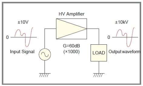
A high-voltage amplifier amplifies an input voltage signal into a high-voltage output waveform while preserving the signal shape, as shown in Fig. 1. These days, the demand for HV amplifiers is growing more and more, and now becoming an indispensable tool for research and development, experiments and integrating to a system for such fields as electronics, physics, biochemical and medical industries. With high-voltage technologies, Matsusada Precision Inc. manufactures various high-voltage amplifiers to meet all customers' requirements.
* We have amplifiers developed especially for electrostatic chuck or PZT. Please ask for details to our sales staff.
Four-quadrant Output Range
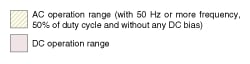
High-voltage amplifiers typically feature a current sink function, enabling stable constant voltage operation regardless of the load type (capacitive or conductive/resistive). (Fig. 2) With their fast response capabilities, these amplifiers are ideal for applications requiring AC output.
Matsusada Precision's high-voltage amplifiers are bipolar and operate across all four quadrants (Areas I, II, III, and IV).
- Vomax: Rated output voltage
- Iomax: Rated output current
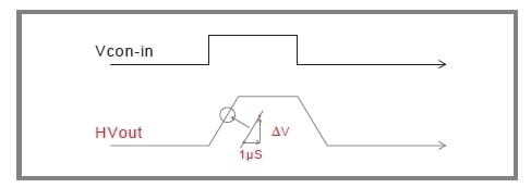
Slew Rate
The responsivity of our high-speed amplifier is determined by slew rate (SR). The step responsivity of our amplifier is shown in Fig. 3.
SR = ΔV/μS
In case the output amplitude is smaller, the response time becomes shorter. AMP series reach to greater than SR =700 V/µs at maximum.
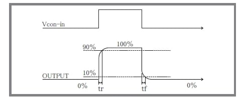
Rise Time (step response)
Step response can be indicated with rise time. (fig.4) Usually, the rise time of the amplifier of response (= bandwidth) fc (Hz) is given in the formula below.
tr ≒ 0.35/fc.
The fall time tf is equal to tr.
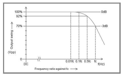
Frequency Response
Response bandwidth is a key specification for our amplifiers. When driving a rated resistive load with a sinusoidal waveform, the output amplitude decreases as the input frequency increases. The frequency response specification refers to the frequency (fc) at which the output amplitude drops to 70% (-3 dB). (Fig. 5)
To ensure a clean output waveform, select a high-voltage amplifier with a sufficiently high frequency bandwidth relative to the required operating frequency. Generally, a bandwidth three to five times the operating frequency is required for sinusoidal waveforms, and about ten times for rectangular waveforms. Insufficient bandwidth can result in reduced output amplitude and significant phase shift.
Note: Avoid continuous input of high-frequency signals exceeding the amplifier's capability. This may cause internal overheating and damage the unit.
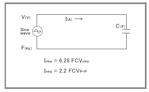
Capacitive Load
When a capacitive load is more than 100 pF (including a stray capacitance of output wire), the resonance in the output may occur. In that case, install 100 Ω (at 0.1 μF) to 1000 Ω (at 1000 pF) of high-voltage resistance in the output in series. Please note that the frequency band is limited when using an amplifier with a capacitive load, as shown in the formula on the right.
In addition, using an amplifier for corona discharge may cause current flow exceeding the rating, which can adversely affect or damage the amplifier. In such cases, as with capacitive loads, please install an output resistor to limit the current.
* Please avoid continuous input of the high-frequency signal, which reduces the output frequency of an amplifier. An amplifier will break because of an increase in internal loss.
Important note for maximizing high-speed amplifier performance
The output cables of high-voltage amplifiers are not shielded. If stray capacitance exists between the output cable and the ground (earth ground or metal objects), the output waveform may become distorted (sinusoidal or step), and excessive current may be drawn. As this current flows in parallel with the load, the following issues may occur:
- Reduced slew rate or frequency response
- Waveform distortion
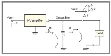
When there is output stray capacitance C, the leakage current by C will be as below.
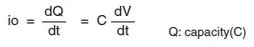
Solution
Make sure to have proper connection to make stray capacitance of High Voltage cable as low as possible.
- Keep the length of the output cable as short as possible.
- Keep the output cable away from floor, desks, or metal objects.
- Have no shielding on the output cable.