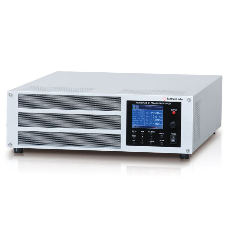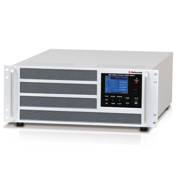
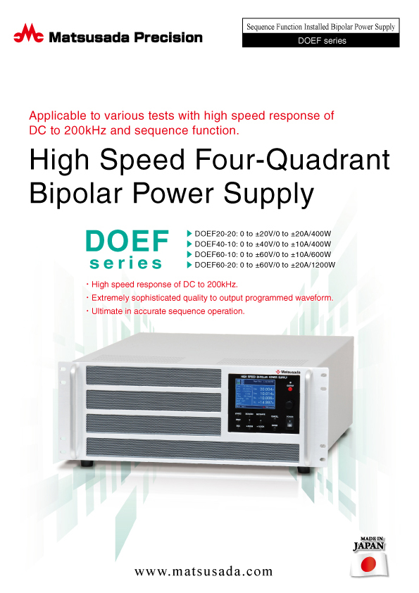
HIGH-SPEED FOUR-QUADRANT BIPOLAR POWER SUPPLY
High-speed DC to 200 kHz response.
Precision sequence operation for advanced testing.
High-fidelity reproduction of programmed waveforms.
- Max Voltage: ±20 V to ±60 V
- Max Power: 1200 W
APPLICABLE TO VARIOUS TESTS WITH HIGH SPEED RESPONSE OF DC TO 200KHZ AND SEQUENCE FUNCTION.
The DOEF series is a four-quadrant power supply capable of both sourcing and sinking current. It is designed for a wide range of applications, from transient response testing to complex simulation. The series features a high-speed response of DC to 200 kHz (CV mode) and includes a built-in function generator to output basic waveforms (sine, square, etc.) as well as user-defined arbitrary waveforms.
With its standard sequence function, output patterns can be programmed in detail directly from the front panel, allowing for easy operation without external control.
FEATURES
- High-Speed Response: Achieves DC to 200 kHz response speed.
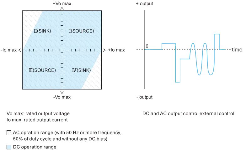
- Four-Quadrant Operation: Capable of both sourcing and sinking current.
- Built-in Function Generator: Generates distortion-free waveforms, including sine, square, and arbitrary waves.
- Advanced Sequence Programming: Supports highly accurate programs with up to 1024 steps.
- Easy Operation: Independent settings for DC and AC parameters via a user-friendly front panel.
- CV/CC Modes: Supports both Constant Voltage (CV) and Constant Current (CC) operations.
- Synchronized Operation: Supports parallel connection of up to 3 units with synchronized trigger and clock for increased power or multi-phase applications.
- Digital Control: External digital control options available.
- Custom Waveforms: Dedicated software allows for 16-bit resolution output and customization of original waveforms (1024 points per cycle).
Operation range
APPLICATIONS
- Voltage fluctuation testing for automotive electrical components (e.g., navigation systems)
- Automotive battery voltage fluctuation simulation (cranking waveform simulation)
- Constant current power supply for electromagnets
- DC motor testing
- Capacitor ripple current testing
- Magnetic material characteristic evaluation
- High-speed power supply for pulse plating
- Loss measurement for transformers and reactors
- Transient current testing for breakers and relays
- Driving piezoelectric elements
- Evaluation of solar inverters (PV inverters)
This product is not designed for charge and discharge of battery.
For battery charging and discharging applications, please refer to the Battery Cycle Tester product page.
Models
We can manufacture other specified voltage, current, and frequency bands written as follows.
Functions
Basic waveform generation
DOEF is equipped with a built-in function generator that produces basic waveforms such as sine, rectangular, and triangle waves.
The frequency range can be set between 0.01 Hz and 200 kHz. Easy adjustments/editions of amplitude, initial phase (for Sinewave), phase shift (for Sine wave), and duty ratio (for rectangular/triangle wave) are possible. DOEF has special features of "soft start" and "soft stop," which enable the initial program rise and fall characteristics of the output.

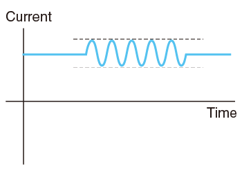
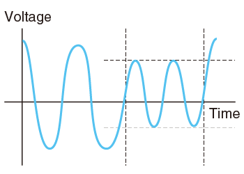
 AC Voltage/Current sweep, frequency sweep
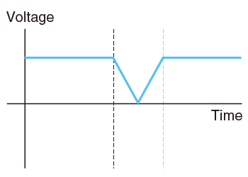
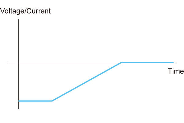 DC Voltage/Current ramp
Applications
Power activation test, various start-up tests of the motor, fluctuation test of the wave shape, etc.
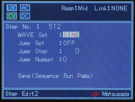
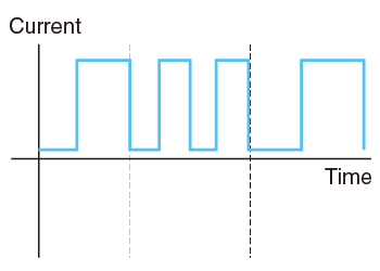
Sequence functions
DOEF is equipped with a built-in function generator that produces basic waves such as sine, rectangular, and triangle waves. Frequency range can be set between 0.01 Hz and 200 kHz (resolution of 0.01 Hz). Easy adjustments/edition of amplitude, initial phase (for sine wave), phase shift (for sine wave), and duty ratio (for rectangular/triangle wave) are possible. DOEF has a special feature of "soft start" and "soft stop" which enables the programming of initial rise and fall characteristics of the output.
Very complex sequence can be created easily with the easily understandable display.
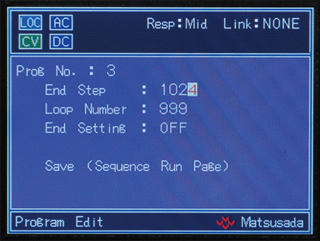
- Step setting time 0.1 ms to 1000 h (resolution of 0.1 ms)
- Maximum 1024 steps per program.
- Maximum 64 programs can be stored in memory for each CC/CV operation
- Program repeat can be set by "endless repeat" or "1 time to 10000 times"
- Multiple programs can be converted to activate
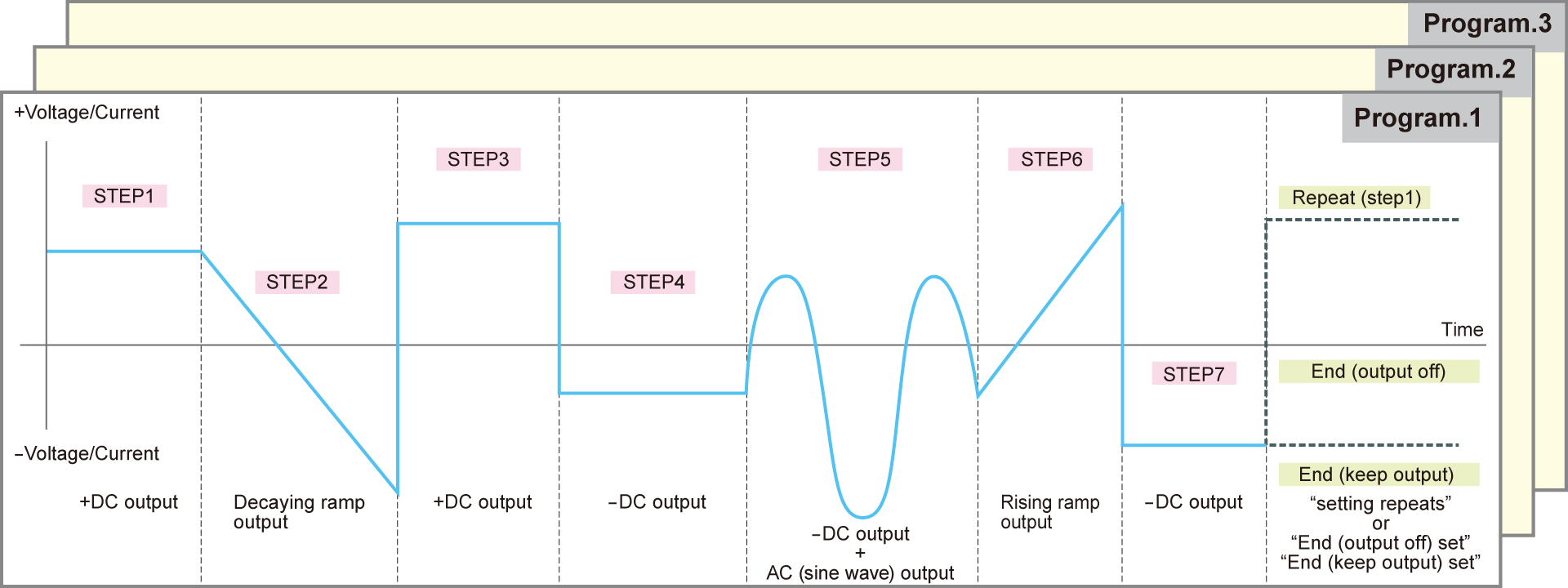
Sequence programming functions help to create complicated waves like the one below to be simply and easily edited.
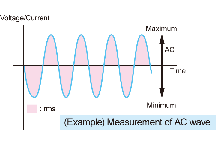
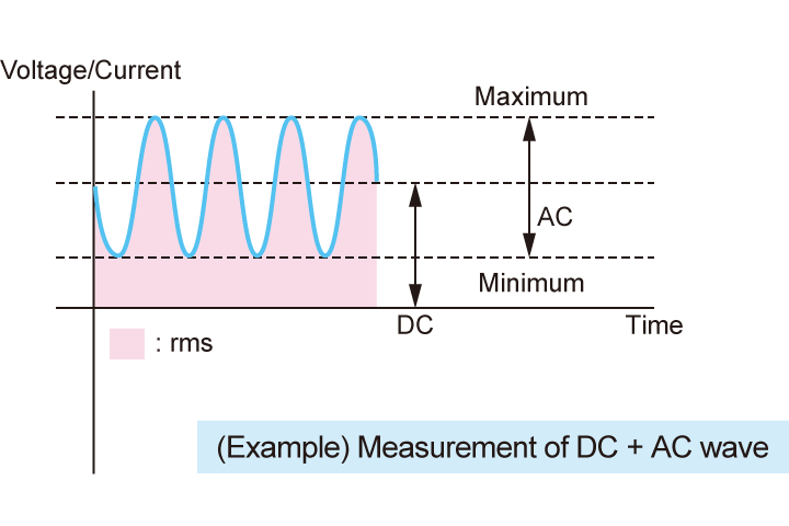
Measurement Function
DOEF is equipped with a measurement function that can measure DC value, AC RMS value, and Max/Min value. Likewise, it is possible to automatically measure a wide range of bandwidth from DC to 120 kHz. 4 parameters are simultaneously displayable, and each of these parameters is individually programmable. As this measurement is a standard feature, no option needs to be purchased. This sophisticated feature will reduce the time for editing output waves and bring up work efficiency.
Synchronized operation (-LSo option)
The following DOEF operations are available for up to three units.
- Synchronous trigger
-
Through a single operation of the master unit, it is possible to match the output timing of ON/OFF in one or two slave units. In turning the output on, the output starting gap between the master and the slave is less than 0.5 µs
* When this option is selected, we provide two meters of dedicated cables for the synchronized trigger function used for two or three devices. - Synchronous clock
-
By providing the clock input of 10 MHz, the individual difference between the oscillators installed on each unit is removed (In this case, there are a few ppm up to several tens ppm in general).
What is more, frequency, accuracy, and sequence-step time are completely unified through the operation. -
Moreover, the product is also available for setting the phase shift difference for the sine wave toward each unit.
(* Please prepare the coaxial cable on both ends of BNC connectors which is not included but required for synchronous clock -
* When the slave unit is required to synchronize in accordance with the waveform set by the master unit, the -LMs option must be taken (in master/slave control). Meanwhile, selecting the -LSo option and the -LMs option simultaneously is not allowed.
- Other functions:
-
Protection function (shutdown or limit settable individually), Key lock function, Switching CV/CC, and Memory function (up to 99) are installed as standard.
OPERABILITY
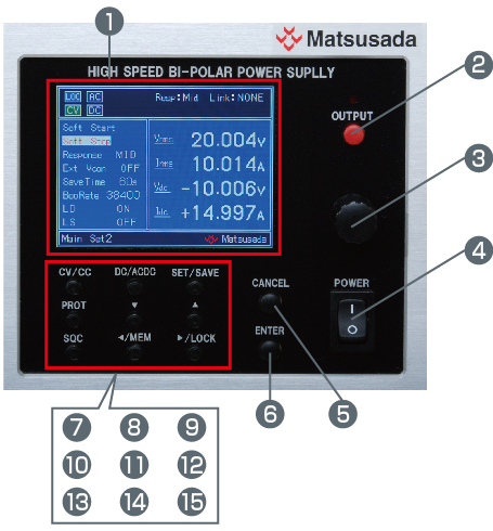
- Display: Display various settings and measurements.
- OUTPUT switch: ON/OFF for output
- Rotary encoder: Change value
- POWER switch: ON/OFF for main power
- CANCEL switch: Cancel settings
- ENTER switch: To confirm and key in
- CV/CC switch: Switch over CV/CC mode
- DC/AC-DC switch: Switch DC/AC+DC mode
- SETTING/STORAGE switch: Make to setting change menu, store memory
- PROTECTION switch: To switch the protection setting menu
- Shift down switch: Shift down each setting item
- Shift up switch: Shift up each setting item
- SEQUENCE switch: Use for switchover of sequence screen or interrupt, or restart of sequence operation
- Shifting left/MEMORY switch: Shift digits of settings to the left and also use switchover memory screens.
- Shifting right/LOCK switch: Shift digits of settings to the right and also use the key lock function
Specifications
- Input voltage
-
100 to 240 Vac, 50/60 Hz, Single-phase (DOEF20-20, DOEF40-10)
200 to 240 Vac, 50/60 Hz, Single-phase (DOEF60-10, DOEF60-20) - Output control
-
[Local] Front panel controls
[External control signal] Vcon-in, Input voltage -10 to +10 V
[Digital remote] Command (Option)
Options
- -LCk *
-
CC-Link interface port
It enables digital remote control via a network of CC-Link. We may accept optimization for specific industrial networks such as Device NET.
Please inquire our sales staff for details.
- -LGob *
-
Optical interface port
With optical communication, isolation control is performed. As complete isolation is performed by means of optical fiber, this enables advanced prevention of erroneous operation involved with transient phenomena caused by surges, inductive lightning, external noise, etc.- -LGob:Optical interface port + optical cable 2 meters
- -LGob(Fc5):Optical interface port + optical cable 5 meters
- -LGob(Fc10):Optical interface port + optical cable 5 meters
- -LGob(Fc20):Optical interface port + optical cable 5 meters
- -LGob(Fc40):Optical interface port + optical cable 5 meters
Select the optional optical interface port (-LGob) when using this DC power supply under the following conditions.
- Noisy environments such as factories (example: when motors or coils are used near loads or power sources).
- If this power supply and your controller (PC or PLC) cannot be installed within 2 meters.
- When there is a possibility of arcing or an output short-circuit.
[Control items] Output ON/OFF, Voltage/Current setting (AC and DC), Switch of constant voltage/constant current, Frequency setting, Waveform setting (sine wave, square wave, and triangle wave), Phase setting (sine wave), Duty setting (square wave and triangle wave)
When using an optical interface port, a separate adapter is required.
- -LMsm: Master machine for master-slave control
-LMss: Slave machine for master-slave control -
By connecting a master machine and a slave machine with dedicated control lines, the master machine can control all slave machines at once. Parallel connection can increase the current that is insufficient for a single operation. Up to three units in total can be connected: one master unit and up to two slave units.
Note: Precautions for using the master-slave operation
- Only the master-slave connection is available for the same model.
- In parallel operation, the frequency range is narrower.
- It can also operate on a single.
- Factory adjustment is required when changing the master-slave combination.
- It is impossible for this to select the "-LSo" option simultaneously. Either communication option (-LGob, -LCk, or -LUs1) is necessary for a master unit when the power supplies in the master-slave connection are controlled by digital communication. Slave units also require these options for their individual operation. (-LGob, -LCk or -LUs1)
- -LSo
-
Synchronized operation
A maximum of 3 units can be operated in parallel.
Accuracy of output frequency and sequence time coincide by synchronizing with multi-units and it is possible to output the same wave altogether. Only in the case of a sine wave, it can output with a phase difference given.
One dedicated cable (length: 2 meters) for the synchronized trigger is attached, except for a cable used for the synchronized clock function.
(It is impossible for this to select -LMsm, -LMss option simultaneously.)
- -LUs1 *
-
USB interface port
Enable digital control with USB. One power supply can be connected to one USB port that the computer is equipped with.
In case the USB port which the computer equipped is not enough, please use a USB hub. However, depending on the USB hub, it may not work correctly.
OS: Microsoft Windows XP/Vista/7/8/10 (Both 32-bit version and 64-bit version are available.)Microsoft Windows is a registered trademark of Microsoft Corporation in the United States and other countries
- -LVs
-
Shifting function for output voltage
Optional 120 Vp-p within the range of -115V to +115 V (only for DOEF60-10 and DOEF60-20).
* These options cannot be selected together. Only one of each can be selected.
How to Order
When ordering, add option No. in the following order by alphabet to Model No.
<Example> DOEF40-10-LMsmUs1, DOEF60-10-LGob(Fc5)SoVs
Accessories
- Optical isolation adapter
-
To use the optical interface, you need to prepare an optical interface adapter separately. The following interface adapters are available according to your controller port.
- CO-E32: LAN to optical interface adapter
- USB-OPT: USB to optical interface adapter
- CO-OPT2-9: RS-232C (9 pin) to optical interface adapter
- CO-OPT2-25: RS-232C (25 pin) to optical interface adapter
- CO-OPT4-25: RS-485 (25 pin) to optical interface adapter
- CO-G32: GPIB to optical interface adapter (Scheduled for discontinuation in December 2028)
Example of communication with optical fiber 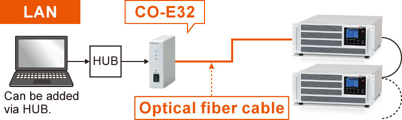
For details, refer to CO/USB series
- AC input cable
-
Standard
400 W modelCABLE TYPE8 

125 V/125 A 2.5 meters
Fixed lengthStandard
more than 600 W modelCABLE TYPE5 

300 V/25 A 2.5 meters Sold separately
400 W modelCABLE TYPE3 
250 V/10 A 2.5 meters
Fixed lengthSold separately
400 W modelCABLE TYPE4 
250 V/10 A 2.5 meters
Fixed length
- Application software
-
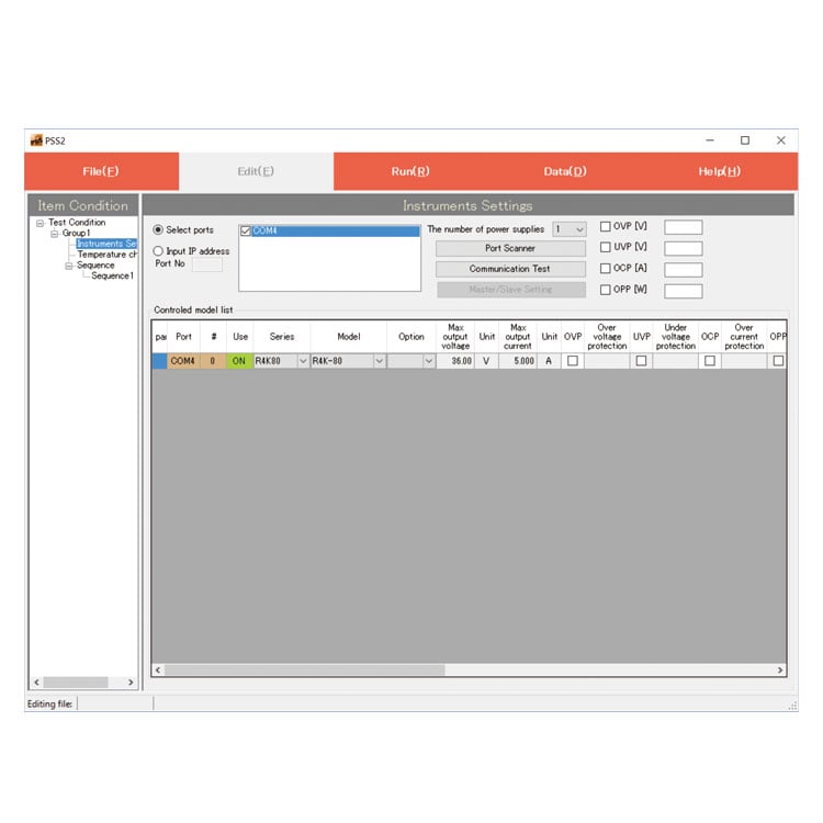
PSS2en series: Remote control, Test workflow design, and Data logging
Click here for the PSS2en seriesPSS2en is the dedicated software that can actuate various power supplies, electronic loads, and digital controllers for power supplies manufactured by Matsusada Precision Inc. with a simple setup.
It is perfect for the aging test, the burn-in test, and the withstand voltage test for electronic parts, as well as for the endurance test, intermittent/continuous operation test, or various simulation tests for automobile electric components.

Dimensions
Tech Notes
As for characteristics of amplifiers
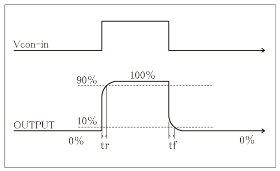
Rise time
(step time) Responsiveness may be expressed with rise time. (see right figure)
Rise time for amplifiers in fc (Hz) of response time (=frequency band) is calculated with the following equation generally.
"tr ≈ 0.35/fc"
Decay time tf is equal to tr.
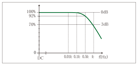
Frequency bandwidth
: at 30 kHz or lower, tr ≈ tf = around 12 μs
: at 20 kHz or lower, tr ≈ tf = around 18 μs
Response Speed
For accurate waveform output, select an amplifier with a frequency bandwidth significantly higher than the application requirement. Generally, a bandwidth 3 to 5 times the fundamental frequency is required for sine waves, and about 10 times for square waves. Insufficient bandwidth not only reduces output amplitude but also increases the phase difference between input and output.
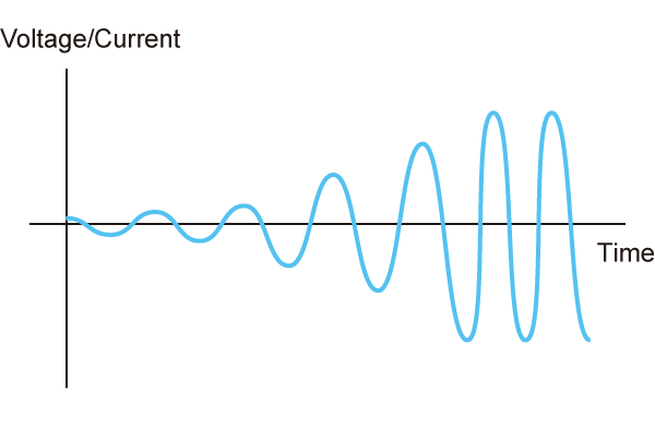
Capacitive Loads
Capacitive loads may cause oscillation. To prevent this, insert a power resistor in series with the output. Note that the frequency bandwidth will be limited by the series resistance and load capacitance.
Inductive Loads
In CC mode, the inductance of the load may cause oscillation. To prevent this, connect a C-R snubber circuit across the output terminals.
Download
If you are unable to download a file
Please try the following solution.
- Please press Ctrl+F5 to clear the cache of your web browser and try again.
- Please restart your web browser and log in again to try again.
- Please change your web browser to another browser and try again.
- Restart the computer and try again.
- Please try again on a different computer.
-
DOEF series Datasheet
Date: 2024-12-11 rev.13
PDF (2,142 KB)
-
Bipolar Power Supplies with Function Generator
Date: 2025-01-20 rev.06
PDF (4,904 KB)
-
Bipolar Power Supplies/Amplifiers Selection Guide
Date: 2023-10-17 rev.03
PDF (6,310 KB)

-
DOEF series Instruction Manual
Date: 2022-6-14 rev.0.7
PDF (2,746 KB)
-
DOEF series Instruction Manual (LGob/LUs1 option)
Date: 2022-3-3 rev.0.3
PDF (1,097 KB)
-
USB driver (-LUs1 Option) for Windows 10, 11
Date: 2025-12-19 rev 2.12.36.20
ZIP(1,629KB)
-
USB driver (-LUs1 Option) for Windows XP, 7, 8, 8.1
Date: 2025-01-22 rev 1.7.6
ZIP (6,504 KB)
Login Required
-
DOEF series Datasheet
Date: 2024-12-11 rev.13
PDF (2,142 KB)
-
Bipolar Power Supplies with Function Generator
Date: 2025-01-20 rev.06
PDF (4,904 KB)
-
Bipolar Power Supplies/Amplifiers Selection Guide
Date: 2023-10-17 rev.03
PDF (6,310 KB)
-
DOEF series Instruction Manual
Date: 2022-6-14 rev.0.7
PDF (2,746 KB)
-
DOEF series Instruction Manual (LGob/LUs1 option)
Date: 2022-3-3 rev.0.3
PDF (1,097 KB)
-
USB driver (-LUs1 Option) for Windows 10, 11
Date: 2025-12-19 rev 2.12.36.20
ZIP(1,629KB)
-
USB driver (-LUs1 Option) for Windows XP, 7, 8, 8.1
Date: 2025-01-22 rev 1.7.6
ZIP (6,504 KB)
On this website, we provide only the latest versions of information and instruction manuals for our products. Therefore, the newest versions of manuals on the website may differ from those that came with products you purchased in the past.