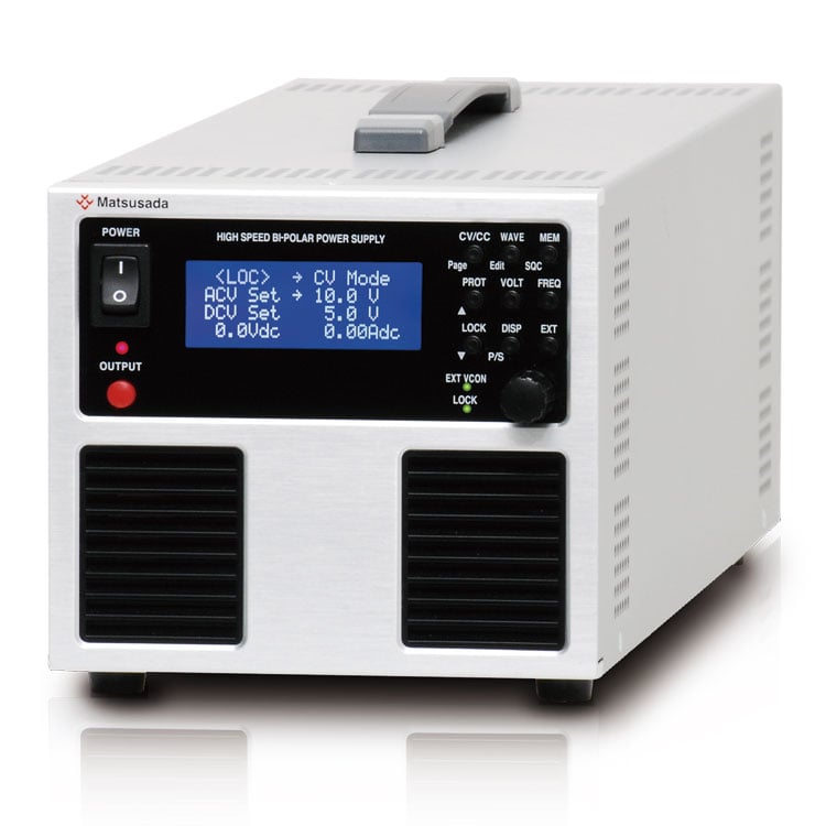
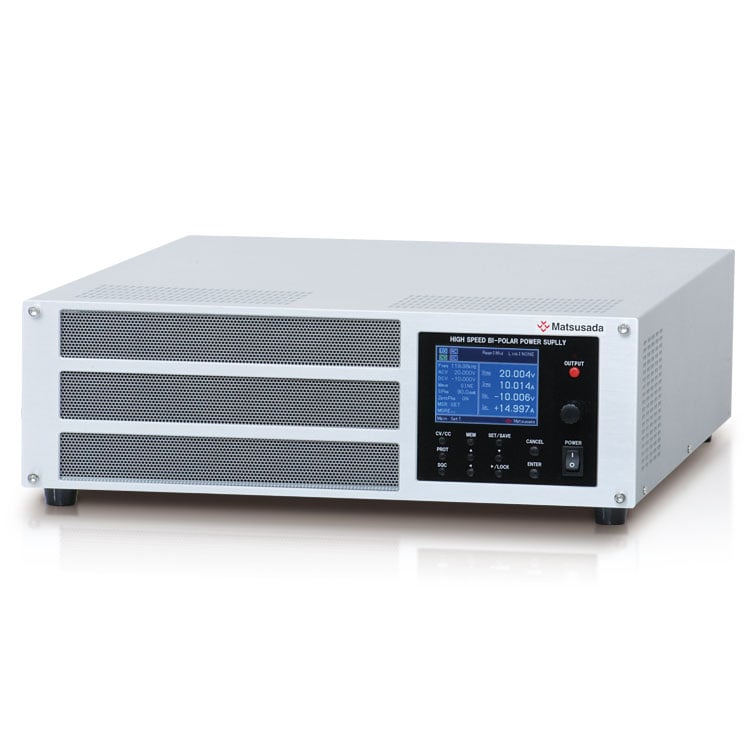
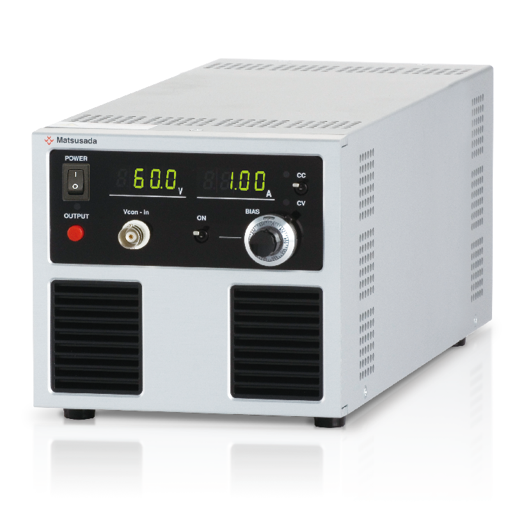
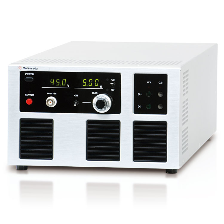
FOUR-QUADRANT HIGH SPEED BIPOLAR POWER SUPPLY
Four-quadrant bipolar power supplies which source and sink power
- Output Voltage:
±10V to ±60V - Max output power:
50W, 60W - Frequency bandwidth:
DC to 30kHz - DC output meter
High Speed Bipolar Power Supply with Function Generator
DJOPF series is a four-quadrant bipolar power supply which sources and sinks electric power. Thanks to the original design, a phenomenal lightweight and compact size power supply, which is 5.51 inches (140 mm) width, and weighs 3 kg, has been achieved. The bipolar amplifier is equipped with a built-in function generator enabling its compact size and fast response. You can use them in 2-mode of a CV (constant voltage) or a CC (constant current). They are ultra-compact and high-speed, driving output proportional to the input waveform such as a sine wave, triangular wave, saw wave, and square wave. DJOPF series is most appropriate for evaluation tests such as solar panels, the instruments driven by a battery, and the IC, which controls the battery.
FEATURES AND BENEFITS
- Response speed
- Newly developed DJOPF series is the most appropriate for transient response tests with such high power and broad bandwidth.
- Four models
- Select a model fitting for your applications from the lineup of various output voltage and current.
- Built-in function generator
- DJOPF includes a sequence function other than a waveform generation function.
- DC or AC output meter
- 3-digit digital meter displays the DC or AC value of the output voltage and current.
- Compact & Light weight
- For maximum compactness and light weight, DJOPF series has been improved for small footprint and easy carry.
- Constant voltage (CV)/Constant current (CC)
- A single switch selects between CV and CC modes.
- Four-quadrant operation
- DJOPF Series can be used both as a high-speed response DC power supply and as an electronic load.
- Complete protective function
- Overvoltage protection, overcurrent protection, and protection against output short circuits are all provided.
APPLICATIONS
- Suitable to evaluate battery-driven equipment to use as a simulated battery
- Inductive loads such as coil and transformer
- Capacitive load like a capacitor
- Various motor tests
- Tests for in-vehicle electrical component
- Evaluation test for solar panel-related devices
- For surface treatment
Note: We do not design this bipolar power supply for charging and discharging batteries.
For batteries charge and discharge application, please refer to the Battery Cycle Tester product page.
Models
| Model | Maximum output | Frequency bandwidth (-3 dB) | ||
|---|---|---|---|---|
| Voltage | Current | Power | ||
| DJOPF10-5 | ±10 V | ±5 A | 50 W | DC to 30 kHz |
| DJOPF20-3 | ±20 V | ±3 A | 60 W | DC to 30 kHz |
| DJOPF30-2 | ±30 V | ±2 A | 60 W | DC to 30 kHz |
| DJOPF60-1 | ±60 V | ±1 A | 60 W | DC to 30 kHz |
- Even more high power model, DOP series, faster model, DOS series, are available. Contact to local sales office for details.
- Please consult with us for specifications other than the below.
Functions
Protections
Voltage limit protection (V limit)
DJOPF is equipped with voltage limit protection, which protects load by limiting output with the value that was set optionally even at abnormal conditions.
Current limit protection (I limit)
DJOPF is equipped with current limit protection, which protects load and power supply by limiting output with the value that was set optionally even at the time of overload.
Overvoltage Protection (OVP)
DJOPF is equipped with overvoltage protection, which protects load by limiting voltage up to approx. 120% of the rated output voltage even at abnormal conditions.
Overcurrent Protection (OCP)
DJOPF is also equipped with overcurrent protection, which protects power supplies and load by limiting current up to approx. 120% of the rated output current.
High speed overcurrent protection
DJOPF is provided with 2 types of overcurrent protections, high-speed overcurrent protection to limit the pulse current, and standard overcurrent protection to limit the static current.
The standard overcurrent protection limits the static current, responding at around 1 ms. Additional fast response type limited current circuit can limit pulse current of square waveforms or from capacitor at approx. 2 times more current of rating.
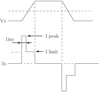
Operation diagram
DJOPF is provided with 2 types of overcurrent protections, high speed overcurrent protection to limit the pulse current, and standard overcurrent protection to limit the static current. The standard overcurrent protection limits the static current, responding at around 1ms. Additional fast response type limited current circuit can limit pulse current of square waveforms or from capacitors at approx. 2 times more current of rating.
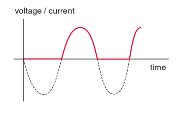
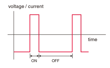
Fundamental Waveform Generated Function
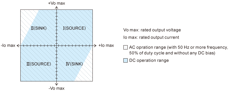
DJOPF series is a bipolar power supply which can perform four-quadrant operation. It can supply (source) and absorb (sink) current in the field of the drawing on the right.
Applications
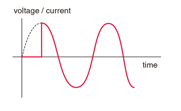
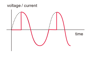
Rush current source for rush current measurement, wave fluctuation test, etc.
Measurement Functions
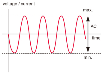
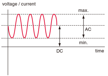
DJOPF is equipped with measurement functions that measure DC value, AC value, maximum value, and minimum value thus Wide frequency ranges, DC to 30 kHz, can be measured automatically, and it is easy to change the setting depending on the application.
Sequence Functions
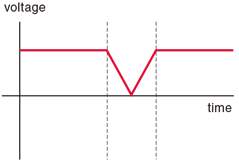
DJOPF is equipped with a sequence function that can program step length, step amplitude, ramp, CV/CC mode, sequence-ending setting, AC superposition, step jump, number of jump, etc. Any desired wave form can be generated making it useful for various experiments, evaluations, and validation applications.
- Step time: 10 ms to 1999 s 999 ms (minimum step time: 1 ms)
- Up to 16 steps per program and settings for 3 programs can be saved.
- Can be set CV/CC mode per program
- Repetition: Infinite, 1 to 999
- DC voltage/current ramp operation, AC voltage/current sweep operation, and AC frequency sweep operation are available.
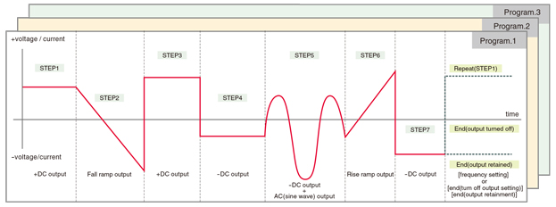
Complicated waveforms such as below can be easily generated just by using the sequence function.
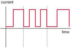
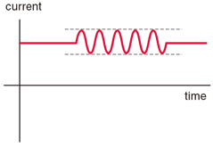
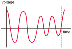
Applications
Motor testing, pulse power supplies, or various evaluation equipment, etc
Memory Function
DJOPF is equipped with both preset and set-up memory. During fundamental wave operation, output voltage (at CV mode), Output current (at CC mode), CV/CC setting, and waveform setting can be saved to 10 set-up memories. Also, sequence programs can be saved in up to 3 programs. Data changes can be saved and data called out very easily.
DJOPF is equipped with
[Protection function],[Key-lock function], and [CV/CC crossover], as standard functions.
Specifications
Options
- -LEt *
-
LAN interface port
Enable digital control via LAN.
Output ON/OFF, Voltage/Current setting (AC and DC), Switch of constant voltage/constant current, Frequency setting, Waveform setting (sine wave, square wave, and triangular wave), Phase setting (sine wave), Duty setting (square wave and triangular wave)
- -LGob *
-
Optical Interface port
With optical communication, isolation control is performed. As complete isolation is performed by means of optical fiber, this enables advanced prevention of erroneous operations involved with transient phenomena caused by surges, inductive lightning, external noise, etc.- -LGob: Optical interface port + optical cable 2 meters
- -LGob(Fc5): Optical interface port + optical cable 5 meters
- -LGob(Fc10): Optical interface port + optical cable 10 meters
- -LGob(Fc20): Optical interface port + optical cable 20 meters
- -LGob(Fc40): Optical interface port + optical cable 40 meters
Select the optional optical interface port (-LGob) when using this DC power supply under the following conditions.
- Noisy environment including factories (Example: Motors or coils are used near power supplies and loads).
- Using with high voltage floating (more than 250 V).
- Installation distance of 2 meters or more between this AC Power Source and a controller such as a computer, laptop, or Programmable Logic Controller (PLC).
- -LNh
-
No handle
The handle for carrying will not be equipped.
- -LS
-
External output ON/OFF (OUTPUT ON/OFF)
It is impossible to select -LGob, -LUs1, and -LEt (Digital interface port) at the same time.
- -LUs1 *
-
USB interface port
Enable digital control via USB.
Output ON/OFF, Voltage/Current setting (AC and DC), Switch of constant voltage/constant current, Frequency setting, Waveform setting (sine wave, square wave, and triangular wave), Phase setting (sine wave), Duty setting (square wave and triangular wave)
* These options cannot be selected together. Only one of each can be selected.
How to Order
When ordering, add Option No. in the following order by alphabet, and input voltage to Model No.
Example: DJOPF60-1-LNhS, DJOPF10-5-Lgob(Fc5)Nh
Accessories
- AC INPUT CABLE
-
Standard CABLE TYPE1 125 V / 10 A 2.5 meters
Fixed length
Sold separately CABLE TYPE3 250 V / 10 A 2.5 meters
Fixed length
Sold separately CABLE TYPE4 250 V / 10 A 2.5 meters
Fixed length
- Interface adapters
-
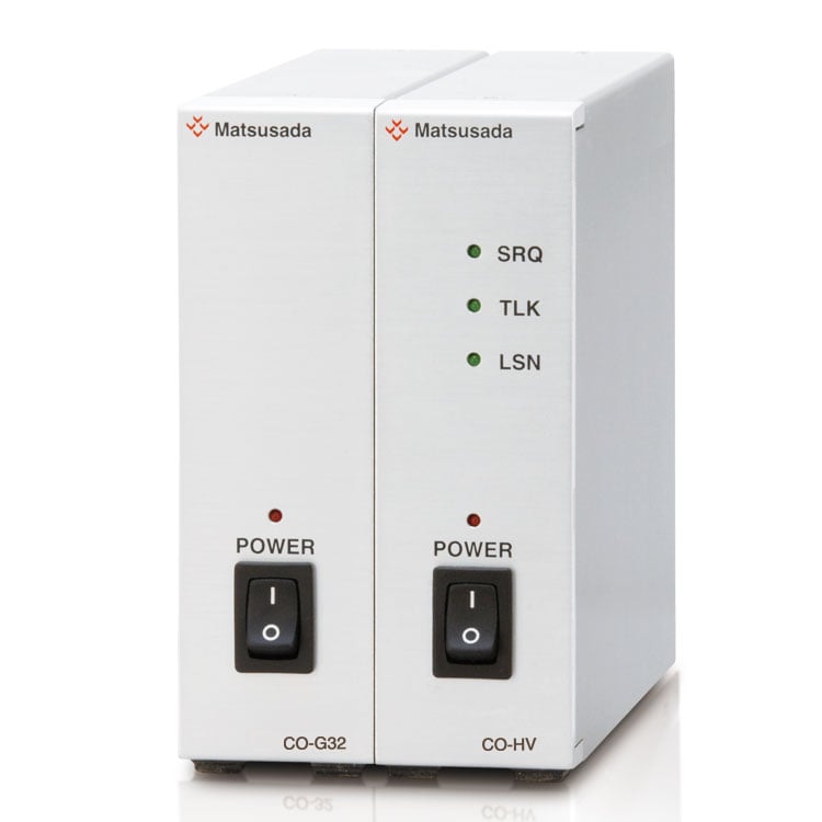
To use the optical interface, you need to prepare an optical interface adapter separately. The following interface adapters are available according to your controller port.
For details, refer to CO/USB series.- CO-E32: LAN to optical interface adapter
- USB-OPT: USB to optical interface adapter
- CO-OPT2-9: RS-232C (9 pin) to optical interface adapter
- CO-OPT2-25: RS-232C (25 pin) to optical interface adapter
- CO-OPT4-25: RS-485 (25 pin) to optical interface adapter
- CO-G32: GPIB to optical interface adapter (Discontinued in December 2028)
Example of communication with optical fiber 
- Application software for power supplies and electronic loads
-
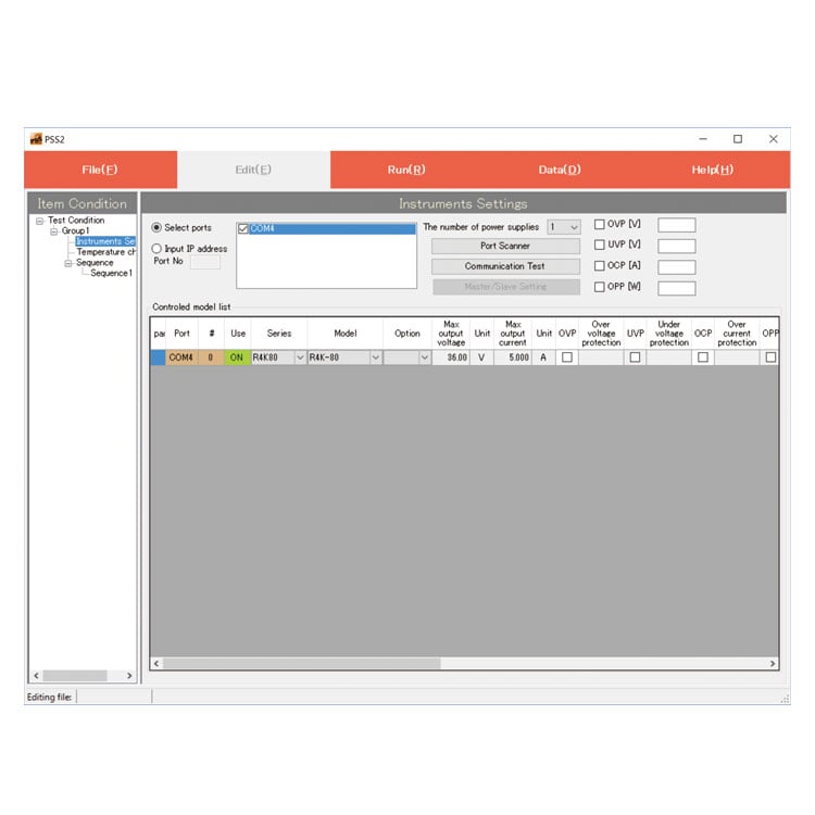
PSS2en series
PSS2en is the dedicated software which can actuate various power supplies, electronic loads and digital controller for power supplies manufactured by Matsusada Precision Inc. with simple set up.
It is the perfect for the aging test, the burn-in test and the withstand voltage test for electronic parts, and for the endurance test, intermittent/continuous operation test or various simulation test for electric component of automobile.
For details, refer to PSS2en page.
Dimensions
Tech Notes
Capacitive Load
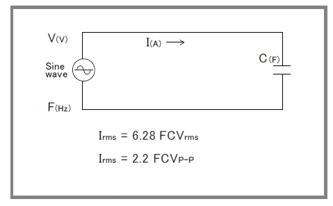
When a capacitive load is more than 100 pF (including a stray capacitance of output wire), the resonance in the output may occur. In that case, install 100-ohm (@0.1 μF) to 1000-ohm (@1000 pF) of high voltage resistance in the output in series. Please note that the frequency band will be limited as the formula written in the right figure when an amplifier is used with a capacitive load.
In addition, when an amplifier is used for use such as a corona discharge, the current which is higher than rating will flow and it will affect the amplifier badly. In this case, as well as the time to use an amplifier with a capacitive load, please install the output resistance and limit the current.
* Please avoid continuous inputting of the high-frequency signal which reduces the output frequency of an amplifier. An amplifier will be broken because of an increase of internal loss.
Download
If you are unable to download a file
Please try the following solution.
- Please press Ctrl+F5 to clear the cache of your web browser and try again.
- Please restart your web browser and log in again to try again.
- Please change your web browser to another browser and try again.
- Restart the computer and try again.
- Please try again on a different computer.
-
DJOPF series Datasheet
Date: 2024-04-18 rev.14
PDF (1,248 KB)
-
Bipolar Power Supplies with Function Generator
Date: 2023-07-26 rev.03
PDF (6,666 KB)
-
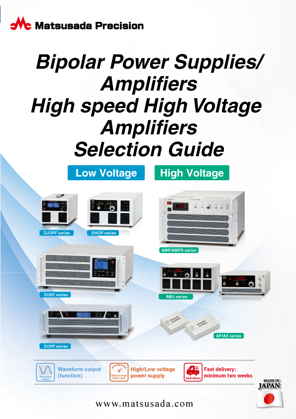
Bipolar Power Supplies/Amplifiers Selection Guide
Date: 2023-10-17 rev.03
PDF (6,310 KB)

-
DJOPF series Instruction Manual
PDF(730KB)

-
DJOPF series Basic Instruction Manual
Date: 2020-11-02 rev0.0
PDF (1,006 KB)
-
DJOPF series USB driver
Date: 2023-08-23 rev1.7.5
ZIP (6,617 KB)
The account registration is necessary for downloading

-
DJOPF series Datasheet
Date: 2024-04-18 rev.14
PDF (1,248 KB)

-
Bipolar Power Supplies with Function Generator
Date: 2023-07-26 rev.03
PDF (6,666 KB)

-
Bipolar Power Supplies/Amplifiers Selection Guide
Date: 2023-10-17 rev.03
PDF (6,310 KB)

-
DJOPF series Instruction Manual
PDF(730KB)

-
DJOPF series Basic Instruction Manual
Date: 2020-11-02 rev0.0
PDF (1,006 KB)
-
DJOPF series USB driver
Date: 2023-08-23 rev1.7.5
ZIP (6,617 KB)
In this website, we provide only the latest version of information including instruction manuals as of our products. Therefore, the newest versions of manuals on the website might be not same as the ones of products you purchased in the past.


