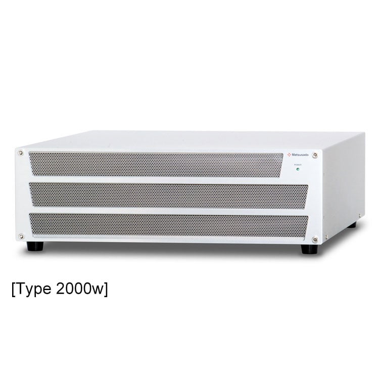
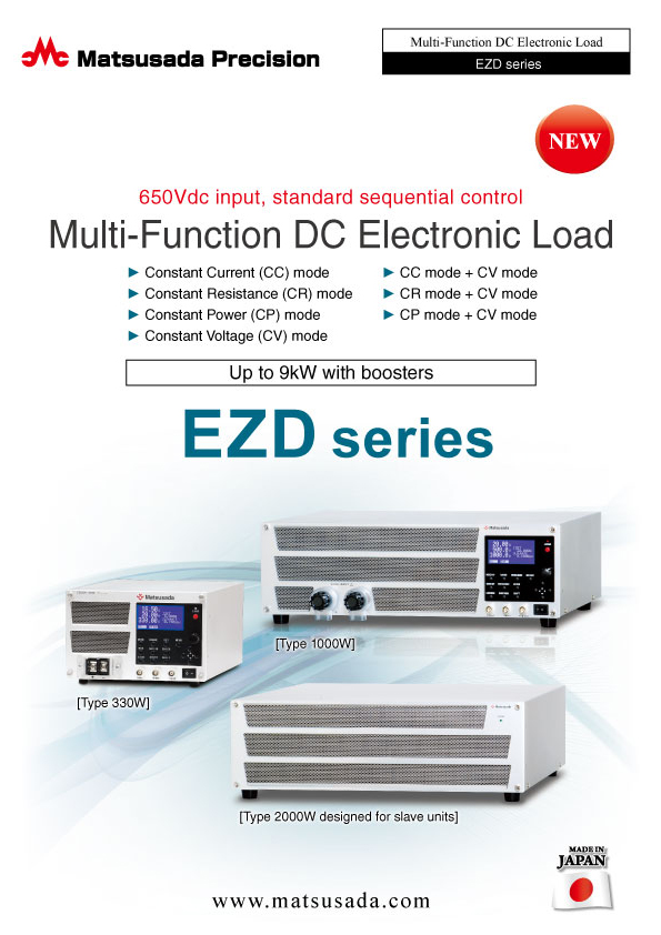
Multi-Function DC Electronic Loads
Scalable up to 9 kW with booster units
- Max Voltage: 650 V
- Max Current: 16.5 A to 100 A
- Max Power: 330 W to 2000 W
- Expandable up to 9 kW with master-slave configuration
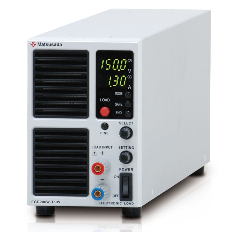
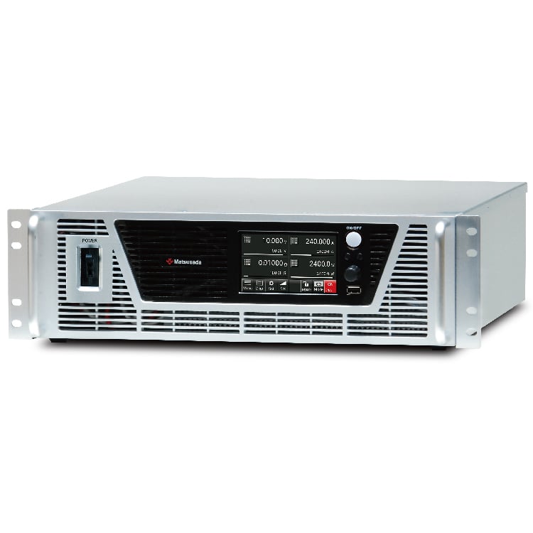
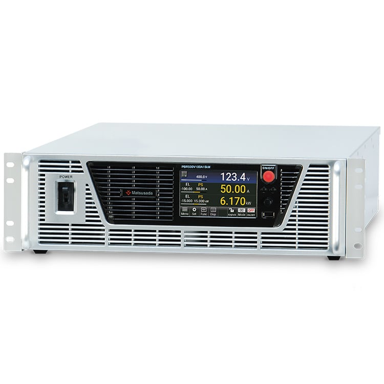
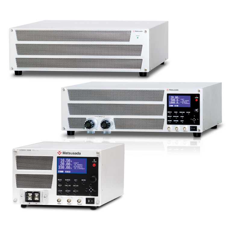
High-Performance DC Electronic Load with 650Vdc Input
The EZD series is a high-performance, multi-function DC electronic load designed for a wide range of testing applications. Featuring seven distinct load modes, including CC, CR, CP, and CV, it offers exceptional flexibility for evaluating power supplies, batteries, and other electronic components. With advanced functions like high-speed sequencing and switching, the EZD series provides precise and repeatable results. Its master-slave capability allows for easy expansion up to 9 kW, making it a scalable solution for both R&D and production environments. Built with Matsusada Precision's commitment to quality, this series delivers the reliability and performance you expect from a product made in Japan.
FEATURES
- Seven different load modes:
Constant Current (CC) mode, Constant Resistance (CR) mode, Constant Power (CP) mode, Constant Voltage (CV) mode,
Constant Current (CC) + Constant Voltage (CV) mode, Constant Resistance (CR) + Constant Voltage (CV) mode,
Constant Power (CP) + Constant Voltage (CV) mode - A large LCD clearly displays current, voltage, and power simultaneously.
- Versatile switching and sequence modes for dynamic load testing.
- Parallel operation with master-slave control for easy capacity expansion.
- Expandable up to 9 kW with booster units.
- Expandable up to 16 units (16 kW) via digital interface
APPLICATIONS
Dynamic Load Testing
The EZD series is ideal for simulating dynamic load conditions to test the transient response of power supplies. The high-speed switching function allows for precise evaluation of voltage stability under fluctuating loads.

Battery Discharge Testing
Suitable for evaluating battery capacity and discharge characteristics. The constant current (CC) and constant power (CP) modes allow for accurate simulation of real-world discharge cycles to determine battery performance and lifespan.

- Current load testing of power supplies
- Discharge testing of batteries and capacitors
- Testing of charge/discharge devices
- Surge absorption of motors
Models
| Models | Rated voltage | Rated current | Rated power |
|---|---|---|---|
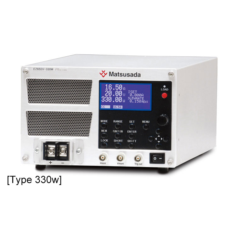
| EZD650V-330W | 650 V | 16.5 A | 330 W |
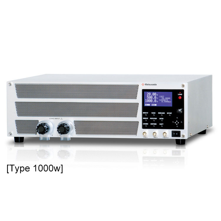
| EZD650V-1000W | 50 A | 1000 W |
| Models | Rated voltage | Rated current | Rated power |
|---|---|---|---|
| EZD650V-2000WB | 650 V | 100 A | 2000 W |
* A single slave operation is not allowed.
Functions
Multi operation mode
EZD series is available with the following seven operation modes.
- Constant Current (CC) mode
- Constant Resistance (CR) mode
- Constant Power (CP) mode
- Constant Voltage (CV) mode
- CC mode + CV mode
- CR mode + CV mode
- CP mode + CV mode
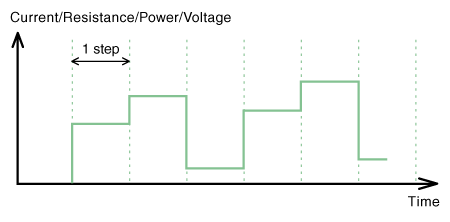
Switching mode
This mode allows for periodic switching between user-defined upper and lower setpoints. The function is available in CC, CR, CP, and CV modes.
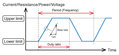
Note: Setting
Upper and Lower Limits
Setting ranges for upper and lower limits vary depending on the selected operation mode.
(The lower limit must be set to a value strictly lower than the upper limit.)
Frequency
- Setting range: 1 Hz to 4 kHz
- Setting resolution: 0.1 Hz
Duty ratio
- Setting range: 5% to 95%
- Setting resolution: 0.1%
- Slew rate (in CC mode)
-
Model Range Setting range Setting resolution EZ650V-1000W H 0.8A/µs to 0.08A/µs 0.001A/µs 80 mA/µs to 8 mA/µs 0.1 mA/µs 8 mA/µs to 0.8 mA/µs 0.01 mA/µs 0.8 mA/µs to 0.08 mA/µs 0.001 mA/µs L 80 mA/µs to 8 mA/µs 0.1 mA/µs 8 mA/µs to 0.8 mA/µs 0.01 mA/µs 0.8 mA/µs to 0.08 mA/µs 0.001 mA/µs 80µA/µs to 8µA/µs 0.1µA/µs EZ650V-330W H 0.26A/µs to 0.026A/µs 0.001A/µs 260 mA/µs to 26 mA/µs 0.1 mA/µs 26 mA/µs to 0.26 mA/µs 0.01 mA/µs 0.26 mA/µs to 0.026 mA/µs 0.001 mA/µs L 26 mA/µs to 2.6 mA/µs 0.1 mA/µs 2.6 mA/µs to 0.26 mA/µs 0.01 mA/µs 0.26 mA/µs to 0.026 mA/µs 0.001 mA/µs 26µA/µs to 2.6µA/µs 0.1µA/µs
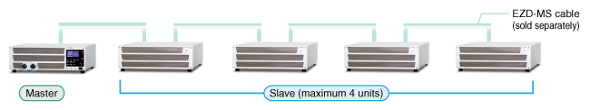
Master-Slave Control
In the EZD series, the operations of up to five units are performed as a single system as long as these types have the same rated voltage. (The series requires optional dedicated cables for the connection.)
The master unit indicates the total values that are obtained from the connected units setting and monitoring as setting and monitoring values. In order to gain the highest load power up to 9 kW, Model EZD650V-1000W should be selected for a master unit, and Model EZD650V-2000WB is also to be selected for four slave units.
All five Model EZD650V-1000W units
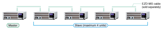
Total load power of 5 kW.
A Model EZD650V-1000W unit and four Model EZD650V-2000WB units
Total load power of 9 kW.
Sequential control
EZD series has two types of sequential control. They are available in CC, CR, CP, and CV modes. The pattern is readily created through the front panel and the exclusive software. The program can save two patterns of the fast sequence as well as 10 patterns of the normal sequence at maximum in the EZD unit, and can also be recalled at any time.
Fast sequence
This function executes a sequence of predefined steps, each with a fixed duration.
- The setting is available with 1,024 steps at maximum.
- Repeat count: 1 to 10000 times or infinity
- Setting range: 10 µs to 1000 ms
- Setting resolution: 100 µs
Normal sequence
This function generates complex test patterns using a combination of ramp and step waveforms.
- Up to 256 steps can be programmed.
- Repeat count: 1 to 10000 times or infinity
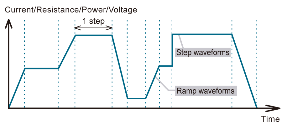
- Setting range: 10 ms to 1000 h
- Setting resolution (Applicable scope):
- 1 ms (1 ms to 1 min)
- 100 ms (1 min to 1 h)
- 1 s (1 h to 10 h)
- 10 s (10 h to 100 h)
- 1 min (100 h to 999 h 59 min)
Short circuit mode
This function simulates a short circuit by minimizing the input impedance.
- CC mode: maximum current of the setting range
- CR mode: minimum resistance of the setting range
- The current value when in short is limited according to the setting of the protection function.
External control function
Using the control terminals on the back of the panel, the setting change and the monitoring of the load status are provided.
- Setting control of each load by the external voltage or the external resistance
- LOAD ON/OFF
- Range switching
- FAULT input
- Input current monitor
- Input voltage monitor
- Status signal output (LOAD ON/OFF, FAULT, SHORT)
Memory function
The EZD series has both a preset memory and 99 setup memories. So, you can easily save and call the memory.
Digital Interface
The EZD series supports digital control via LAN, USB, RS-232C, RS-485, and GPIB using optional interface adapters. Additionally, up to 16 units (total 16 kW) can be connected and controlled via the digital interface for large-scale applications.
Note: An optional interface adapter is required for digital control. See Accessories
Specifications
- Input voltage
- 100 to 240 Vac, 50/60 Hz, Single-phase
- Operating mode
-
Constant Current (CC) mode
Constant Resistance (CR) mode
Constant Power (CP) mode
Constant Voltage (CV) mode
Constant Current (CC) + Constant Voltage (CV) mode
Constant Resistance (CR) + Constant Voltage (CV) mode
Constant Power (CP) + Constant Voltage (CV) mode - Load control
-
[Local] "SET" Key and rotary encoder on the front panel
[Analog remote] External control voltage 0 to 10 Vdc or external 10kΩ potentiometer
[Digital remote] Command
Options
- -LGob *
-
Optical Interface Port
This option changes the standard interfaces to a built-in optical interface port. By combining this option with an adapter for optical connection (sold separately), communication between the control device and the power supply can be controlled in an isolated state. Be sure to select this option when using the product in the following environments.Select the optional optical interface port (-LGob) when using this DC power supply under the following conditions.
- Noisy environments such as factories (example: when motors or coils are used near loads or power sources).
- If this power supply and your controller (PC or PLC) cannot be installed within 2 meters.
- When there is a possibility of arcing or output short-circuit.
- -LGob: Optical interface port + optical cable 2 meters
- -LGob (Fc5): Optical interface port + Optical cable 5 meters
- -LGob (Fc10): Optical interface port + optical cable 10 meters
- -LGob (Fc20): Optical interface port + optical cable 20 meters
- -LGob (Fc40): Optical interface port + optical cable 40 meters
Accessories
- Adapters for various digital interfaces (additional products)
-
To use Matsusada Precision’s digital interface, you need to prepare a digital interface adapter separately.
The following interface adapters are available according to your controller port.For details, refer to CO/USB series.- CO-E32m: LAN adapter
- CO-U32m USB adapter
- CO-MET2-9 RS-232C (9 pin) adapter
- CO-MET2-25: RS-232C (25 pin) adapter
- CO-MET4-25 RS-485 (25 pin) adapter
- CO-G32m GPIB adapter (Scheduled for discontinuation in December 2028)
Adapter for digital interface 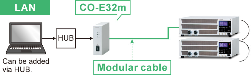
- Various optical interface adapters (additional products)
-
To use the optical interface, you need to prepare an optical interface adapter separately.
The following interface adapters are available according to your controller port.For details, refer to CO/USB series.- CO-E32: LAN to optical interface adapter
- USB-OPT: USB to optical interface adapter
- CO-OPT2-9: RS-232C (9 pin) to optical interface adapter
- CO-OPT2-25: RS-232C (25 pin) to optical interface adapter
- CO-OPT4-25: RS-485 (25 pin) to optical interface adapter
- CO-G32: GPIB to optical interface adapter (Scheduled for discontinuation in December 2028)
Example of communication with optical fiber 
- AC Input Cable
-
Standard CABLE TYPE1 

125 V/10 A 2.5 meters
Fixed lengthSold separately CABLE TYPE3 
250 V/10 A 2.5 meters
Fixed lengthSold separately CABLE TYPE4 
250 V/10 A 2.5 meters
Fixed length
- Master-slave communications cable
-
EZD-MS cable 1
Master-slave communications cable 0.55 metersEZD-MS cable 2
Master-slave communications cable 0.3 meters
- Rack mount flange 3U
-
This rack mount flange 3U attaches to both sides of the EZD series when it is stored in a 19" rack cabinet.
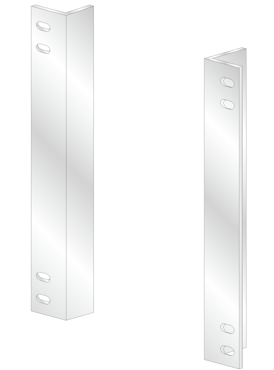
Rack mount flange
- Application software
-
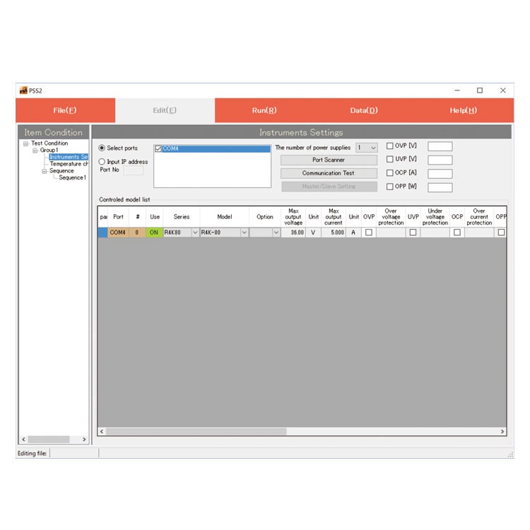
PSS2en series: Remote control, Test workflow design, and Data logging
Click here for the PSS2en seriesPSS2en is the dedicated software that can actuate various power supplies, electronic loads, and digital controllers for power supplies manufactured by Matsusada Precision Inc. with a simple setup.
It is perfect for the aging test, the burn-in test, and the withstand voltage test for electronic parts, as well as for the endurance test, intermittent/continuous operation test, or various simulation tests for automobile electric components.

Dimensions
Download
If you are unable to download a file
Please try the following solution.
- Please press Ctrl+F5 to clear the cache of your web browser and try again.
- Please restart your web browser and log in again to try again.
- Please change your web browser to another browser and try again.
- Restart the computer and try again.
- Please try again on a different computer.
-
EZD series Datasheet
Date: 2026-03-16 rev 11
PDF (4,440 KB)
-
How to Use DC Power Supplies
Date: 2026-04-16 rev 10
PDF (1,335 KB)
-
DC Electronic Load Selection Guide
Date: 2025-5-20 rev.05
PDF (5,477 KB)

-
EZD series Outline Drawing (DXF, PDF)
Date: 2024-07-25
ZIP (1,076 KB)
Login Required
-
EZD series Datasheet
Date: 2026-03-16 rev 11
PDF (4,440 KB)
-
How to Use DC Power Supplies
Date: 2026-04-16 rev 10
PDF (1,335 KB)
-
DC Electronic Load Selection Guide
Date: 2025-5-20 rev.05
PDF (5,477 KB)
-
EZD series Outline Drawing (DXF, PDF)
Date: 2024-07-25
ZIP (1,076 KB)
On this website, we provide only the latest versions of information and instruction manuals for our products. Therefore, the newest versions of manuals on the website may differ from those that came with products you purchased in the past.