Wiring and Operation
Connection of load
- Use short, heavy-gauge lead wires for the connection.
- Please use PVC electric cable (105°C) that can fully tolerate the voltage used. Use cables with sufficient current-carrying capacity. If using remote sensing, ensure the voltage drop across the load wires does not exceed the sensing compensation limit (typically 0.5 V per lead).
| AWG | mm2 | Max current (A) |
|---|---|---|
| 18 | 0.823 | 2.3 |
| 16 | 1.31 | 3.7 |
| 14 | 2.08 | 5.9 |
| 12 | 3.31 | 9.3 |
| 10 | 5.26 | 15 |
| 8 | 8.37 | 24 |
| 6 | 13.3 | 37 |
| 4 | 21.1 | 60 |
| 2 | 33.6 | 94 |
| 1 | 42.4 | 119 |
| 1/0 | 53.5 | 150 |
| 2/0 | 67.4 | 190 |
| 3/0 | 85.0 | 239 |
| 4/0 | 107 | 302 |
Use several cables or copper bars for models over 302 A.
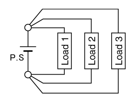
Parallel connection of load
Good
Bad
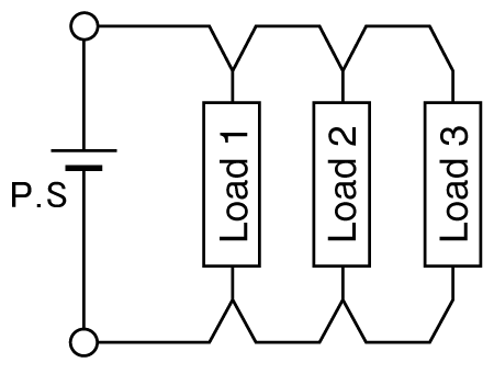
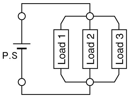
Wiring Configuration: Avoid daisy-chaining loads, as this can increase voltage drop and interference. Connect each load directly to the power supply output terminals (star connection) or use a low-impedance bus bar.
Specifications Definitions
Unless otherwise specified in the product datasheet or manual, the following definitions apply. Specifications represent values at rated output (full scale) after a two-hour warm-up period. The specification in this brochure indicates the value at rated power output (full scale) shown after a two-hour warm-up.
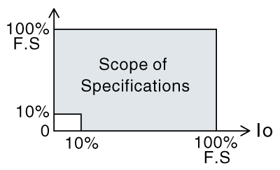
Scope of Specifications
The following specifications are applied within a range of 10 to 100% of the rated output.
- Ripple
- Stability
- Regulations
- Temperature coefficient
- Linearity of output
- Linearity of monitor
- Linearity of indications
Ripple
Ripple values are measured in rms and include high-frequency noise components.
Preset
Preset values are approximate. For precise settings, enable the output and measure it directly. For precise voltage settings, measure the output with a calibrated meter under no-load conditions. To set the current limit accurately, short the output terminals and adjust the current setting to the desired value while monitoring the output.
Recommended Products
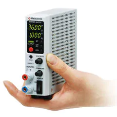
Matsusada Precision's high-performance DC power supplies