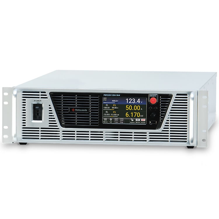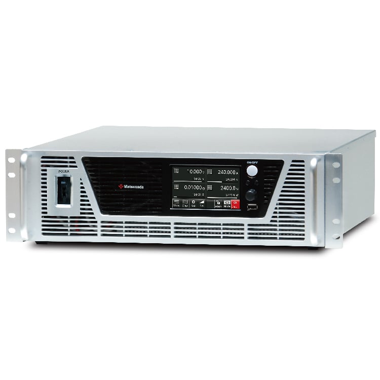
HIGH POWER DC ELECTRONIC LOAD
- Test voltages up to 150 V
- Sink current up to 240 A, 480 A
- High Power: 1200 W, 2400 W
- Multiple operating modes
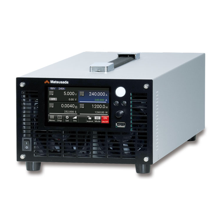
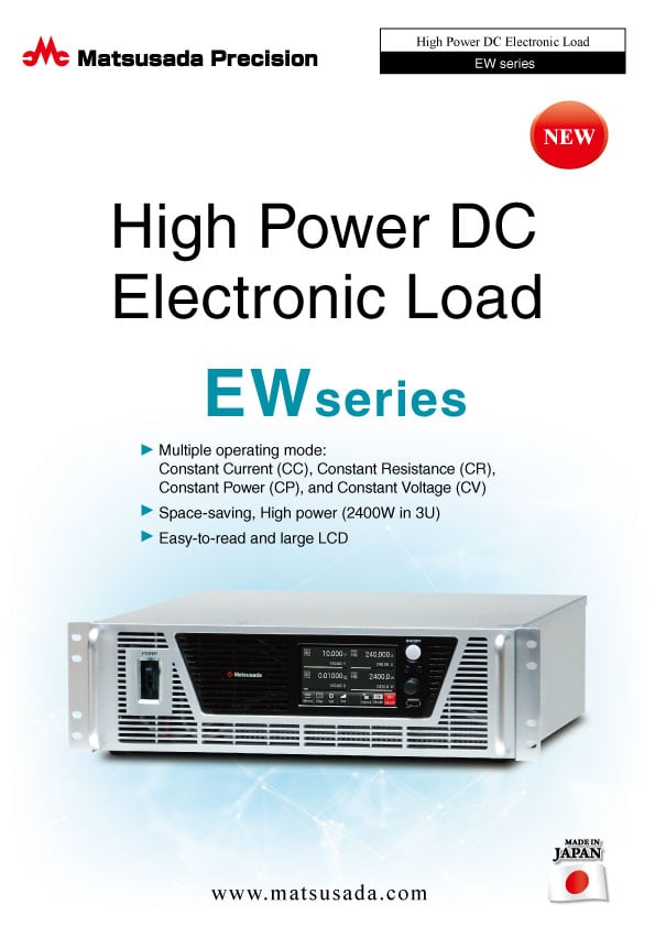
The EW series is a high-power DC electronic load featuring a space-saving design.
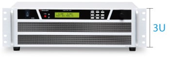
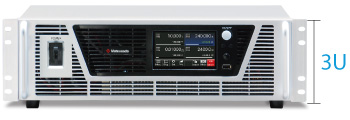
The EW Series is a compact 3U high-power DC electronic load delivering up to 2400W. With four operating modes-CC, CR, CP, and CV-it also offers fast transient testing through a dynamic mode and automated multi-step sequences.
Its large LCD provides clear monitoring of voltage, current, and power, while USB memory enables simple data logging and sequence management. Scalable up to 12kW with booster units, the EW Series is an ideal solution for testing DC-DC converters, batteries, and solar cells-combining high performance, ease of use, and trusted Japanese quality.
FEATURES AND BENEFITS
- Four operating modes: Constant Current (CC), Constant Resistance (CR), Constant Power (CP), Constant Voltage (CV)
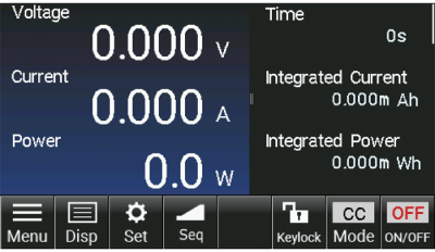
- Multi-item displays of current, voltage, and power on the large LCD screen
- High power density in a compact footprint
- Wide variety of testing applications with the switching mode and programmable function
- Expandable up to five units (12 kW) with booster
MAIN APPLICATIONS
- Load for switching power supply testing
- Absorbing surge current from brushless DC motors
- Evaluation testing of DC relay and DC switches
- Load for in-vehicle DC/DC converter testing
- Discharge test of a high current rechargeable battery and electric double-layer capacitor
- I-V characteristic test of solar cells
Models
| Models | Rated voltage | Rated current | Rated power |
|---|---|---|---|
| EW150V-2400W | 150 V | 480 A | 2400 W |
| EW150V-1200W Coming soon | 150 V | 240 A | 1200 W |
| Models | Rated voltage | Rated current | Rated power |
|---|---|---|---|
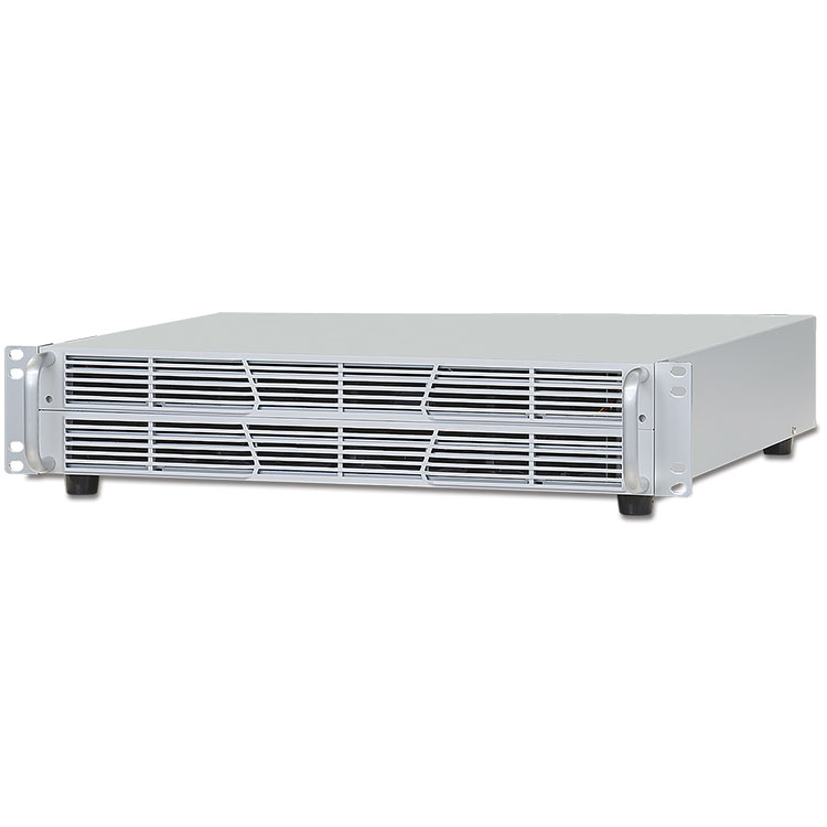
| EW150V-2400WB Coming soon | 150 V | 480 A | 2400 W |
* The booster unit cannot operate independently.
Functions
1.6 Times More Load Power Than Conventional Models
Four Operating Modes
Constant Current (CC) Discharge
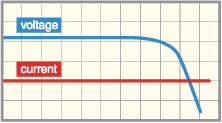
A set current is discharged. Even if the terminal voltage changes during discharge, a constant current can flow.
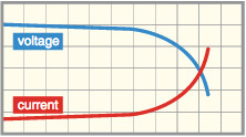
Constant Resistance (CR) Discharge
A set resistance is used to discharge. The discharge current value is determined according to the set value by measuring the terminal voltage value.
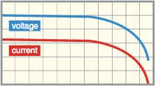
Constant Power (CP) Discharge
A set power value is used to discharge. If the terminal voltage changes during discharge, a certain amount of power can be consumed according to the change.
Constant Voltage (CV) Discharge
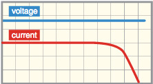
A set voltage value is used to discharge. Even if the terminal current changes during discharge, it can be operated at a constant voltage.
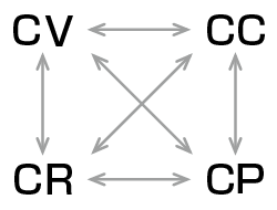
Auto switching between operating modes
With the auto-switching, the operating mode where the load current is minimized is automatically set in response to the set value. The individual function of CC+CV mode, CR+CV mode, and CP+CV mode using the auto-switching remains as it is.
Switching Mode
This mode allows you to periodically switch between two values.
It is available in CC mode, CR mode, CP mode, and CV mode.
-
Slew rate (in CC mode, Range H)
at 10 V or more and at an input of 30% or more of the rated current, with no voltage drop due to wiring
[EW150V-1200W] 16 A/μs to 0.5 mA/μs, setting resolution 0.5 mA/μs
[EW150V-2400W] 32 A/μs to 1 mA/μs, setting resolution 1 mA/μs -
Frequency
0.1 Hz to 20 kHz Setting resolution 0.1 Hz -
Duty cycle
0 to 100% Setting resolution 0.1%

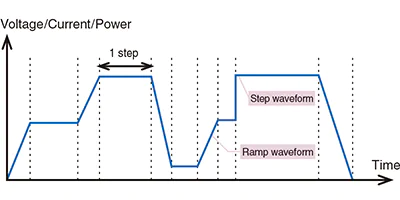
Sequence Function
- Current/Voltage/Power/Resistance setting the value of each program
(Available for the mode where the load current is minimized) - Step setting time 10 us to 1000 h
- The setting is available for up to 1,024 steps of 10 programs.
- Repetition frequency: infinite, or 1 time to 10000 times
The sequence function offers a set of step time, amplitude, ramp, and along with the end of the sequence, so you can create programs on the front panel.
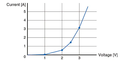
VI Mode
It is possible to register up to 128 by combining the voltage value with the current one. The mode provides a simulation of loads such as laser diodes and LEDs which have non-linear resistance characteristics.
Short Circuit Mode
Easily transfers to a low impedance state.
- CC/CP mode: Maximum
- CR mode: Maximum conductance

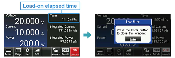
The Function of Total Current and Power Calculation
Displays the Elapsed Time of load-on and total current, total power.
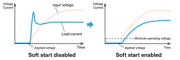
Soft Start/Stop
Allows slow rise/fall of the current at load-on/off. It is desirable to match the rise time on the power supply to reduce the occurrence of the current overshoot.
- Time: 10 μs to 500 ms
- Rising waveform: linear/saturation curve
- Minimum operating voltage: 0.05 V
Timer Setting
Automatically turns off the load after a specified time elapses from load-on.
- Setting time: 1 second to 10000 hours
Input/Output of Sequence Program
Reads and writes sequence programs using USB memory.
Spreadsheet software is available for files in CSV format.
Data Logging Function
Records current and voltage measurement values to USB memory at regular intervals.
- Interval: 0.1 s to 300 s

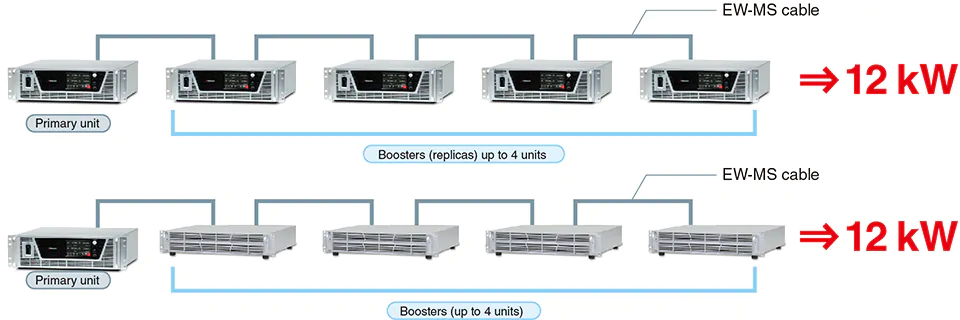
Parallel Operation Mode
Up to five EW series electronic loads can be combined to operate as a single device.
The primary unit shows the summed set value and the monitored value.
The power can be increased to 12 kW by combining four boosters with EW150V-2400W.
EW-MS cables or commercially available LAN cables can be used for the connection.
Specifications
- Input voltage
- 100 to 240 Vac, 50/60 Hz, Single-phase
- Operating mode
-
Constant Current (CC) mode
Constant Resistance (CR) mode
Constant Power (CP) mode
Constant Voltage (CV) mode
Automatic switching between operating modes - Load control
-
[Local] "SET" Key and rotary encoder on the front panel
[Analog remote] External control voltage 0 to 10 Vdc or external 10kΩ potentiometer
[Digital remote] Command
Options
- -LGob *
-
Optical Interface port
This option changes the standard interfaces to a built-in optical interface port. By combining this option with an adapter for optical connection (sold separately), communication between the control device and the power supply can be controlled in an isolated state. Be sure to select this option when using the product in the following environments.- -LGob: Optical interface port + optical cable 2 meters
- -LGob(Fc5): Optical interface port + optical cable 5 meters
- -LGob(Fc10): Optical interface port + optical cable 10 meters
- -LGob(Fc20): Optical interface port + optical cable 20 meters
- -LGob(Fc40): Optical interface port + optical cable 40 meters
Optical isolation adapter is required.Select the optional optical interface port (-LGob) when using this DC Electronic Load under the following conditions.
- Noisy environments such as factories (example: when motors or coils are used near loads or power sources).
- If this power supply and your controller (PC or PLC) cannot be installed within 2 meters.
- When there is a possibility of arcing or output short-circuit.
- -LRs *
-
RS-232C/RS-485 interface port
Using RS-232C/RS-485 communications, output controlling and operation status monitoring of these devices can be provided.
* Selecting each individual option simultaneously in -LGob and -LRs is not allowed.
How to Order
When ordering, add option No. to Model No. in alphabetical order followed by the input voltage.
Example:EW150V-2400W-LGob(Fc20)
ADDITIONAL PRODUCTS
- EW-MS cable 1 meter
-
Dedicated cable for controlling booster
The cable is used for the primary unit controlling the boosters (replicas).
The cable is required for one booster. You can substitute it with a commercially available LAN cable.
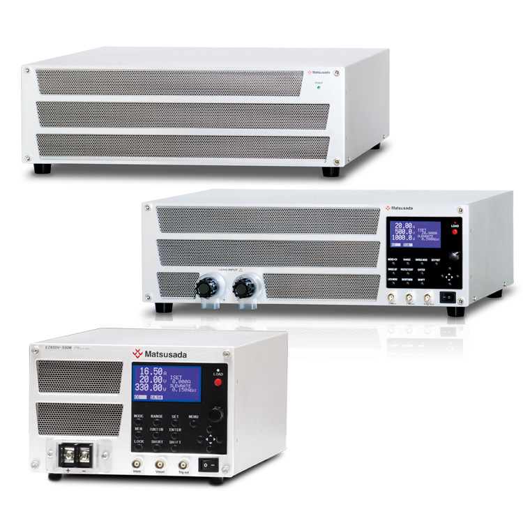
- Optical isolation adapter
-
To use the optical interface, you need to prepare an optical interface adapter separately. The following interface adapters are available according to your controller port.
- CO-E32: LAN to optical interface adapter
- USB-OPT: USB to optical interface adapter
- CO-OPT2-9: RS-232C (9 pin) to optical interface adapter
- CO-OPT2-25: RS-232C (25 pin) to optical interface adapter
- CO-OPT4-25: RS-485 (25 pin) to optical interface adapter
- CO-G32: GPIB to optical interface adapter (Scheduled for discontinuation in December 2028)
Example of communication with optical fiber 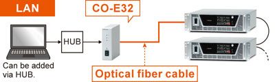
For details, refer to CO/USB series
- Rack mount shelf
-
Model: RMO-177H-EW
Rack mount shelf for storing electronic load units together in a 19-inch rack. Holds up to two EW150V-1200W models. For details, please refer to the datasheet of "RMO series" 19-inch rack mount shelf.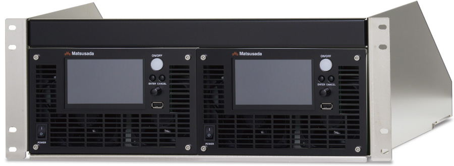
- AC input cable
-
Sold separately CABLE TYPE3 

250 V / 10 A 2.5 meters Fixed length
Sold separately CABLE TYPE4 
250 V / 10 A 2.5 meters Fixed length
-
How to Order
To order, please specify the model No.
Example: EW-MS cable, CO-E32, CABLE TYPE 3
- Application software
-
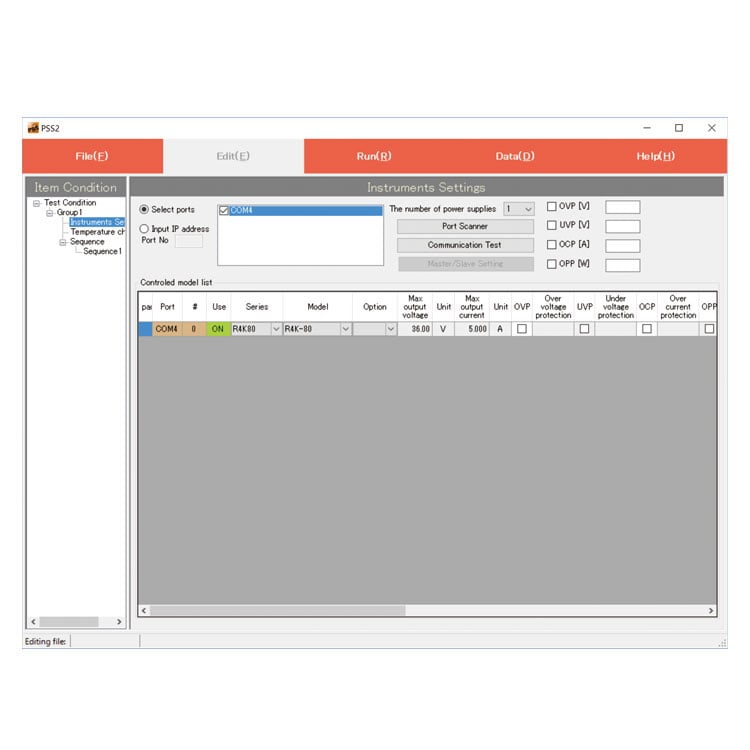
PSS2en series: Remote control, Test workflow design, and Data logging
PSS2en is the dedicated software that can actuate various power supplies, electronic loads, and digital controllers for power supplies manufactured by Matsusada Precision Inc. with a simple setup.
It is perfect for the aging test, the burn-in test and the withstand voltage test for electronic parts, and for the endurance test, intermittent/continuous operation test, or various simulation tests for electric components of automobiles.
For details, refer to PSS2en page.
Dimensions
Download
If you are unable to download a file
Please try the following solution.
- Please press Ctrl+F5 to clear the cache of your web browser and try again.
- Please restart your web browser and log in again to try again.
- Please change your web browser to another browser and try again.
- Restart the computer and try again.
- Please try again on a different computer.
-
EW series Datasheet
Date: 2025-11-24 rev 13
PDF (2,157 KB)
-
How to Use DC Power Supplies
Date: 2026-04-16 rev 10
PDF (1,335 KB)
-
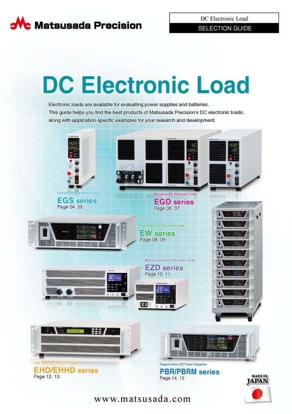
DC Electronic Load Selection Guide
Date: 2025-5-20 rev.05
PDF (5,477 KB)

-
EW series Basic Instruction Manual (Japanese and English)
Date: 2024-8-29 rev 1.3
PDF (846 KB)
-
EW series Instruction Manual
Date: 2026-06-16 rev 1.4
PDF (2,613 KB)
Login Required
-
EW series Datasheet
Date: 2025-11-24 rev 13
PDF (2,157 KB)
-
How to Use DC Power Supplies
Date: 2026-04-16 rev 10
PDF (1,335 KB)
-
DC Electronic Load Selection Guide
Date: 2025-5-20 rev.05
PDF (5,477 KB)
-
EW series Basic Instruction Manual (Japanese and English)
Date: 2024-8-29 rev 1.3
PDF (846 KB)
-
EW series Instruction Manual
Date: 2026-06-16 rev 1.4
PDF (2,613 KB)
On this website, we provide only the latest versions of information and instruction manuals for our products. Therefore, the newest versions of manuals on the website may differ from those that came with products you purchased in the past.