
HIGHLY-FUNCTIONAL SMALL DC CHARGE-DISCHARGE POWER SUPPLY
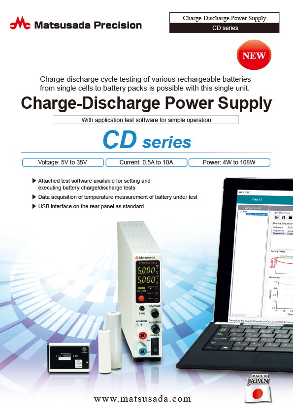
Charge-discharge cycle testing of various rechargeable batteries from single cells to battery packs is possible with this single unit.
- Voltage: 5V to 35V
- Current: 0.5A to 10A
- Power: 4W to 108W
- With battery test software
Optimum for charge-discharge test of various rechargeable batteries
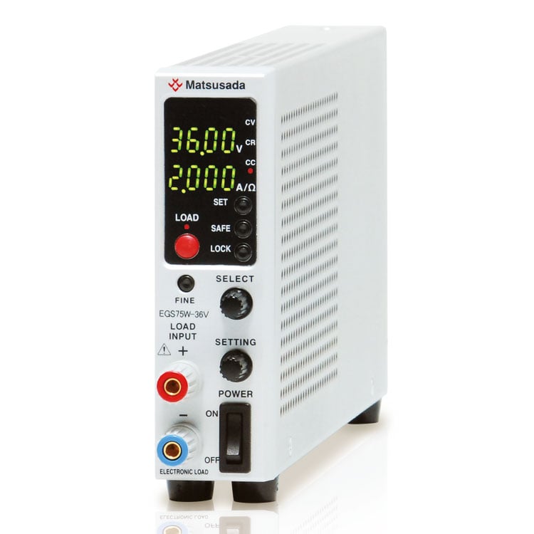
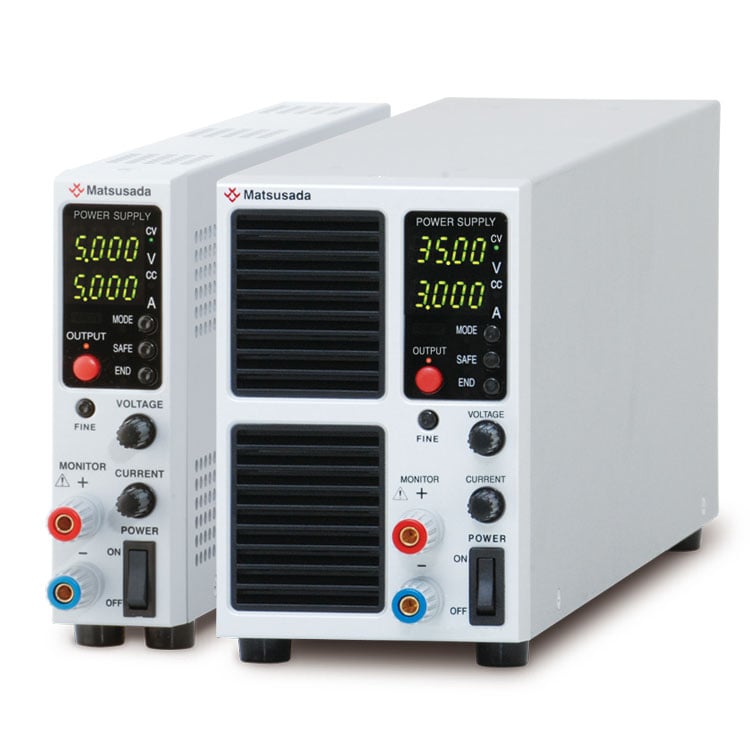
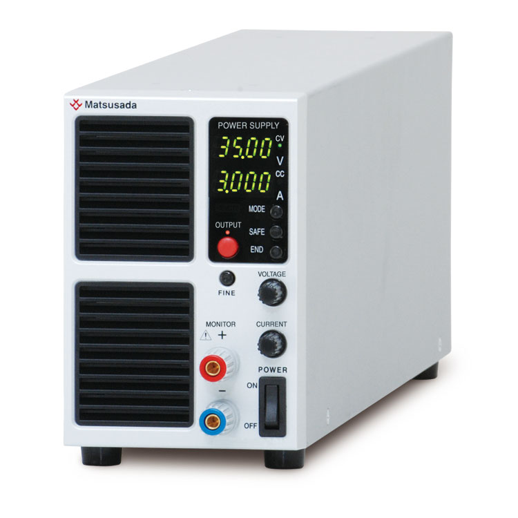
CD series is an ultra-small design DC charge-discharge power supply that can be easily installed on a test bench. When a battery is connected to the CD series, it safely performs charge and discharge cycle tests while monitoring the battery's voltage, current, and temperature.
With a compact width of 1.38" and 3.31", it can handle up to 108 W charge-discharge. The attached software is very convenient when you conduct multi-channel charge-discharge test.
As the natural discharge during downtime after charging can be minimized by suction prevention function, this product is optimum for battery test.
FEATURES AND BENEFITS
- Designed for various charge/discharge testing of batteries
- Attached test software available in various charge/discharge testing
- Built-in USB interface is standard
- Available for load voltage 0 V input two models
- Data acquisition of battery temperature measurement
- High resolution D/A and A/D converter

APPLICATIONS
- Designed for various charge/discharge testing of batteries
Models
| Model | Maximum Output Voltage [V] | Input Voltage [V] | Maximum I/O Current [A] |
Maximum I/O Power [W] |
AC input | ||
|---|---|---|---|---|---|---|---|
| 120 Vac ±10% 50 Hz/60 Hz single phase [A] |
200 Vac * ±10% 50 Hz/60 Hz single phase [A] |
230 Vac * ±10% 50 Hz/60 Hz single phase [A] |
|||||
| Input Current (typ.) | |||||||
| CD5-5-LThUs1 | 5 V | 1.5 to 5 V | 5 A | 25 W | 1 A | 0.5 A | 0.35 A |
| CD5-10-LThUs1 | 10 A | 50 W | 2 A | 1 A | 0.7 A | ||
| CD8-0.5-LLzThUs1 | 8 V | 0 to 8 V | 0.5 A | 4 W | 1 A | 0.5 A | 0.35 A |
| CD8-1-LLzThUs1 | 1 A | 8 W | 1 A | 0.5 A | 0.35 A | ||
| CD8-0.5-LThUs1 | 1.5 to 8 V | 0.5 A | 4 W | 1 A | 0.5 A | 0.35 A | |
| CD8-1-LThUs1 | 1 A | 8 W | 1 A | 0.5 A | 0.35 A | ||
| CD8-2-LThUs1 | 2 A | 16 W | 1 A | 0.5 A | 0.35 A | ||
| CD8-3-LThUs1 | 3 A | 24 W | 1 A | 0.5 A | 0.35 A | ||
| CD18-0.5-LThUs1 | 18 V | 1.5 to 18 A | 0.5 A | 9 W | 1 A | 0.5 A | 0.35 A |
| CD18-1-LThUs1 | 1 A | 18 W | 1 A | 0.5 A | 0.35 A | ||
| CD18-2-LThUs1 | 2 A | 36 W | 1 A | 0.5 A | 0.35 A | ||
| CD18-4-LThUs1 | 4 A | 72 W | 2 A | 1 A | 0.3 A | ||
| CD18-6-LThUs1 | 6 A | 108 W | 2.5 A | 1.3 A | 0.93 A | ||
| CD35-3-LThUs1 | 35 V | 1.5 to 35 V | 3 A | 105 W | 2.5 A | 1.3 A | 0.93 A |
* Option available soon
Discontinued Products
Sales of the following models ended on April, 2024. We continue to support the products.
| Model | Maximum Output Voltage [V] | Input Voltage [V] | Maximum I/O Current [A] |
Maximum I/O Power [W] |
AC input | ||
|---|---|---|---|---|---|---|---|
| 120 Vac ±10% 50 Hz/60 Hz single phase [A] |
200 Vac ±10% 50 Hz/60 Hz single phase [A] |
230 Vac ±10% 50 Hz/60 Hz single phase [A] |
|||||
| Input Current (typ.) | |||||||
| CD5-5-LUs1 | 5 V | 1.5 to 5 V | 5 A | 25 W | 1 A | 0.5 A | 0.35 A |
| CD5-10-LUs1 | 10 A | 50 W | 2 A | 1 A | 0.7 A | ||
| CD8-0.5-LLzUs1 | 8 V | 0 to 8 V | 0.5 A | 4 W | 1 A | 0.5 A | 0.35 A |
| CD8-1-LLzUs1 | 1 A | 8 W | 1 A | 0.5 A | 0.35 A | ||
| CD8-0.5-LUs1 | 1.5 to 8 | 0.5 A | 4 W | 1 A | 0.5 A | 0.35 A | |
| CD8-1-LUs1 | 1 A | 8 W | 1 A | 0.5 A | 0.35 A | ||
| CD8-2-LUs1 | 2 A | 16 W | 1 A | 0.5 A | 0.35 A | ||
| CD8-3-LUs1 | 3 A | 24 W | 1 A | 0.5 A | 0.35 A | ||
| CD18-0.5-LUs1 | 18 V | 1.5 to 18 V | 0.5 A | 9 W | 1 A | 0.5 A | 0.35 A |
| CD18-1-LUs1 | 1 A | 18 W | 1 A | 0.5 A | 0.35 A | ||
| CD18-2-LUs1 | 2 A | 36 W | 1 A | 0.5 A | 0.35 A | ||
| CD18-4-LUs1 | 4 A | 72 W | 2 A | 1 A | 0.3 A | ||
| CD18-6-LUs1 | 6 A | 108 W | 2.5 A | 1.3 A | 0.93 A | ||
| CD35-3-LUs1 | 35 V | 1.5 to 35 V | 3 A | 105 W | 2.5 A | 1.3 A | 0.93 A |
Functions
Three Charge Modes
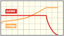
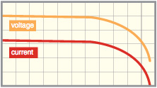
Constant Current/Constant Voltage (CC/CV) charge
By setting both of current value and voltage value, the output exceeding the value you set can be disabled.
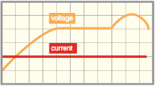
Constant Current (CC) charge
The charge is carried out at the current value you set. Even if the terminal voltage changes during charge, a constant current can be passed.
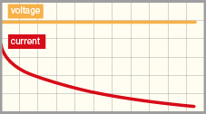
Constant Voltage (CV) charge
The charge is carried out at the voltage value you set. Even if the charge current changes, a constant voltage can be applied.
Charge completion condition setting
- Setting of time
- The time can be set up to 999 hours 59 minutes 59 seconds by one-second unit. If the time reaches the setting time, the charge is completed.
- Setting of voltage
- Set the voltage value to complete the charge. If the terminal voltage of the battery reaches the setting value, the charge is completed (only at a constant current charge).
- Setting of current
- Set the current to complete the charge. If the current that is passed to the battery reaches the setting value, the charge is completed (only at a constant voltage charge).
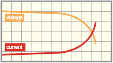
- Setting of -△V
- For some batteries, the voltage increases when the charge is completed, and then the voltage decreases to complete the charge. The voltage reduction value at that time is measured and the charge is completed if the voltage decreases by -△V you set.
Three Discharge Modes
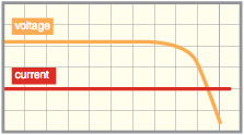
Constant Current (CC) Discharge
The discharge is carried out at the current value you set. Even if the terminal voltage changes during discharge, a constant current can be passed.
Constant Resistance (CR) discharge
The discharge is carried out at the resistance value you set. The value of terminal voltage is measured and the current value for discharge is decided according to the setting value.
Constant Power (CP) Discharge
The discharge is carried out at the power value you set. If the terminal voltage changes during discharge, constant power can be consumed according to the change.
Discharge completion condition setting
- Setting of time
- The time can be set up to 999 hours 59 minutes 59 seconds by one-second unit. If the time reaches the setting time, the charge is completed.
- Setting of voltage
- Set the voltage value to complete the charge. If the terminal voltage of the battery reaches the setting value, the charge is completed.
Digital control function
| Control function | ON/OFF setting, Charge/Discharge operation switching, Charge/Discharge mode switching | |
|---|---|---|
| Various status displays (Charge/Discharge status, Operation mode: OVP, OCP, UVP, OPP, OTP, OHP, OBP, ACF, RS) | ||
| Collective control when multiple devices are connected | ||
| Setting function | I/O voltage setting, I/O current setting | Voltage/Current value mode (maximum rated voltage/current value) |
| OVP/OCP/UVP/OPP setting | Voltage/Current power value mode (maximum overvoltage/overcurrent/over discharge/over power protection value) | |
| Constant power/Constant resistance setting | Power value mode (maximum rated power value), Resistance value mode (0.2 Ω to 18 kΩ) | |
| Reading function | I/O voltage measurement, I/O current measurement | Voltage/Current value mode (maximum rated voltage/current value) |
| I/O voltage setting value, I/O current setting value | Voltage/current value mode (maximum rated voltage/current value) | |
| OVP/OCP/UVP/OPP setting | Voltage/Current power value mode (maximum overvoltage/overcurrent/over discharge/ over power protection value) | |
| Constant power/Constant resistance/ Temperature setting value |
Power value mode (maximum rated power value), Resistance value mode (0.2 Ω to 18 kΩ), Temperature value mode (0 to +100°C) | |
Remote function
External output ON/OFF
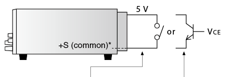
| OUTPUT | Relay | Open collector |
|---|---|---|
| ON | SHORT | VCE 0.4 V or less |
| OFF | OPEN | VCE 2 V or more |
Sink current 1 mA
* As +S is set to common, input the external control voltage based on +S. Otherwise, a failure may be caused.
Remote sensing
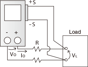
The voltage reduction (VO-VL) due to resistance (R) of the output line and degradation of stability due to contact resistance are prevented (up to 0.5 V).
Various protection functions
For the charge-discharge tests, various protection functions are prepared for protecting your devices and this unit.
- OVP (overvoltage protection)
- OCP (overcurrent protection)
- UVP (under (low) voltage protection)
- OPP (over-power protection)
- OTP (internal over temperature protection 1)
- OHP (internal over temperature protection 2)
- OBP (over battery temperature protection)
- ACF (input voltage reduction)
- RS (remote sense line reverse connection protection)
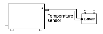
Battery Temperature Measurement Function
The temperature of a battery is measured by the temperature sensor. If the temperature becomes abnormal, charge and discharge are stopped in an urgent manner to protect the battery.
Specifications
Options
- -LGmb
-
digital interface board
Digital control with LAN/USB/RS-232C/RS-485/GPIB is available.
-LGmb devices connected in a daisy chain can control up to 16 units.* As for the option, USB interface is not attached.
* For more information on the digital interface, refer to CO/USB series datasheet.- -LGmb: digital interface + communication cable 2 meters length
- -LGmb(Mc0.15): digital interface + communication cable 0.15 meters length
- -LGmb(Mc0.5): digital interface + communication cable 0.5 meters length
A separate adapter (sold separately) is required for connection. For details, click here.
- -LZ
-
carrying handle
The carrying handle is attached to the upper surface. (only the model of dimension diagram C of datasheet)
- -L(200V)
-
200 Vac ±10% input on sale soon
For the input current, refer to the "MODELS".
- -L(230V)
-
230 Vac ±10% input on sale soon
For the input current, refer to the "MODELS".
How to Order
For Model No. please be sure to contact the sales representative.
Accessories
- Adapters for various digital interfaces (additional products)
-
To use Matsusada Precision’ s digital interface, you need to prepare a digital interface adapter saparately. The following interface adapters are available according to your controller port.
For details, refer to CO/USB series.- CO-E32m: LAN adapter
- CO-U32m: USB adapter
- CO-MET2-9: RS-232C (9 pin) adapter
- CO-MET2-25: RS-232C (25 pin) adapter
- CO-MET4-25: RS-485 (25 pin) adapter
- CO-G32m: GPIB adapter (Discontinued in December 2028)
Adapter for digital interface 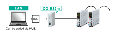
AC Input Cable
|
Standard Except for -L(200V), -L(230V) option |
CABLE TYPE1 |  |
 |
125 V / 10 A | 2.5 meters Fixed length |
|---|---|---|---|---|---|
|
Standard For -L(200V), -L(230V) option |
CABLE TYPE3 | |
 |
250 V / 10 A | 2.5 meters Fixed length |
| Sold separately | CABLE TYPE4 | |
 |
250 V / 10 A | 2.5 meters Fixed length |
Various tools are prepared so that you can use the CD series more conveniently.
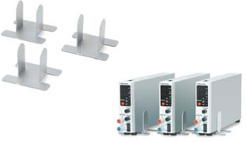
- Stand [1.38-inch wide models]
-
Convenient for a single use for an individual device.
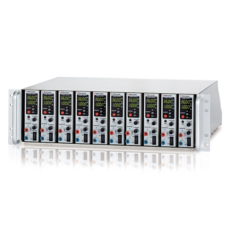
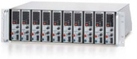
- Rack mount shelf [RMO series]
-
10 units * /1 shelf are stored in the cabinet and each unit can be removed easily. [* 1.38-inch wide models]
Dimensions
Software
Battery Cycle Test Software "CD-BC" (Attached) *
CD-BC is dedicated software for remote-controlling our company's charge-discharge power supply. It realizes ideal power supply control when you carry out the charge-discharge test for various rechargeable batteries such as lithium-ion batteries. It enables the setting of test conditions, test execution, confirmation of test status, and display and saves test results.
* “CD-BC” is only controlling one channel version. If you want to control multiple channels, you need to purchase the CD-BC-512 ch.
Features
- The charge-discharge test (creating test condition to executing to checking) can be executed by dedicated software only.
- Executing the charge-discharge test by using the charge-discharge power supplies made our company of maximum 256 units.
- Checking the datalog during the test.
- Executing the charge-discharge test linked with Espec's temperature chamber.
- Charge-discharge test for various batteries: lead-acid, nickel-cadmium (NiCd), nickel-metal hydride (NiMH), lithium-ion (Li-ion), and lithium-ion polymer (Li-ion polymer), are supported.
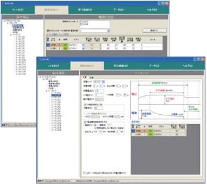
1. Creating of test condition
Create a condition for charge and discharge.
Up to 16 patterns of charge and discharge sequence can be set. You can set various test conditions according to purpose such as selection of charge and discharge mode and setting of each protection function.
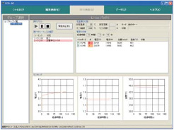
2. Executing of test
Execute the test for each group you set.
On the execution screen, necessary information such as sequence, thermostatic chamber, the status of power supply, voltage value, and current value at test can be monitored on one screen. If the test is executed for multiple groups at the same time, the statuses can be collectively monitored.
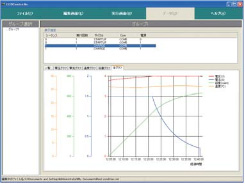
3. Checking of measurement data
Check the completed test data. You can check the data for each cycle of the sequence. You can check the status for each unit time and end condition of each cycle.
The data can be displayed as a graph.
Operation Requirement *
* It does not guarantee the operation.
- Microsoft and Windows are registered trademarks of Microsoft Corporation in the USA and other countries.
- Other product names are registered trademarks of each company.
| OS | Windows 10 (32/64 bit), 8.1 (32/64 bit), 8 (32/64 bit), 7 (32/64 bit), Vista (32/64 bit), Microsoft .NET Framework4.0SP1 | ||||||
|---|---|---|---|---|---|---|---|
| Language | English/Japanese | ||||||
| CPU | Pentium4 or more | ||||||
| RAM | 1 GB or more | ||||||
| HDD | 500 MB or more free capacity | ||||||
| Monitor | 1024 x 768 or more resolution | ||||||
| Connection port | USB port or COM port is required depending on the connection. | ||||||
| USB port | 1 port or more (When using CD-BC-512ch, USB protection key connection is required.) | ||||||
Download
If you are unable to download a file
Please try the following solution.
- Please press Ctrl+F5 to clear the cache of your web browser and try again.
- Please restart your web browser and log in again to try again.
- Please change your web browser to another browser and try again.
- Restart the computer and try again.
- Please try again on a different computer.
-
CD series Datasheet
Date: 2024-04-17 rev.11
PDF (2,684 KB)
-
DC POWER SUPPLIES SELECTION GUIDE
Date: 2023-12-06 rev.00
PDF (1,202 KB)

-
CD series Basic Instruction Manual
Date: 2020-09-11 rev 0.0
PDF (1,076 KB)
-
CD series Instruction Manual
Date: 2020-10-12 rev0.1
PDF (2,039 KB)
-
CD/CDPU series software CD-BC Instruction Manual
Date: 2021-06-14 rev 3.5
PDF (2,744 KB)
-
CD series USB Driver
Date: 2023-08-23 rev1.7.5
ZIP (6,617 KB)
The account registration is necessary for downloading
-
CD series Datasheet
Date: 2024-04-17 rev.11
PDF (2,684 KB)
-
DC POWER SUPPLIES SELECTION GUIDE
Date: 2023-12-06 rev.00
PDF (1,202 KB)
-
CD series Basic Instruction Manual
Date: 2020-09-11 rev 0.0
PDF (1,076 KB)
-
CD series Instruction Manual
Date: 2020-10-12 rev0.1
PDF (2,039 KB)
-
CD/CDPU series software CD-BC Instruction Manual
Date: 2021-06-14 rev 3.5
PDF (2,744 KB)
-
CD series USB Driver
Date: 2023-08-23 rev1.7.5
ZIP (6,617 KB)
In this website, we provide only the latest version of information including instruction manuals as of our products. Therefore, the newest versions of manuals on the website might be not same as the ones of products you purchased in the past.