Basics of Analog Remote Control
To achieve high performance, stability, and low ripple when using analog remote control with DC power supplies, proper connection and grounding are essential. Ensuring the correct setup is the most critical step in installation.
Remote Control
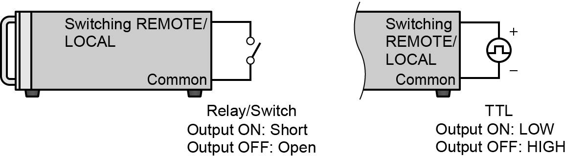
- Remote/Local switching
-
This signal switches between the remote control and the local control.
-
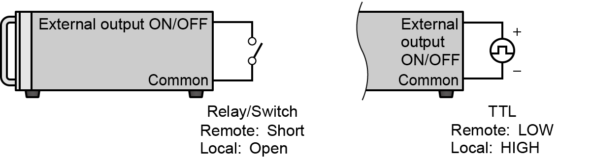
External Output ON/OFF
(Formerly: Remote switch (LS)) -
Connect a relay or switch to control output ON/OFF.
-
Interlock (Not safety interlock)
(Formerly: Door switch (LD)) -
Connect the terminal to a switch on a door or protective cover, and when that contact opens, the output stops. (This is not a safety interlock as defined by the machinery directive.)
For more details, see our glossary entry: Interlock
- External Inhibit (INH)
-
Enables/disables the output.
Programming
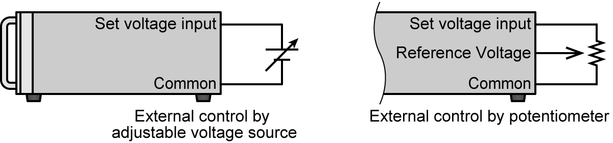
Output voltage, current, etc. can be controlled by an external analog remote. There are two methods for analog programming of output and protection value.
- External control by adjustable voltage source <example> 0 to 10 V
- External control by potentiometer
<example> 0 to 10 kΩ
- Output voltage
-
Analog programming of output voltage.
- Output current
-
Analog programming of output current.
- Output power
-
Analog programming of output power.
- Overvoltage protection (OVP)
-
Analog programming of overvoltage protection value. Turns off the output and protects the load in the event of an error due to overvoltage.
- Overcurrent protection (OCP)
-
Analog programming of overcurrent protection value. Turns off the output and protects the load in the event of an abnormality due to overcurrent such as a short circuit.
- Overpower protection (OPP)
-
Analog programming of overpower protection value. Turns off the output and protects the load in the event of an error due to overpower.
Monitoring
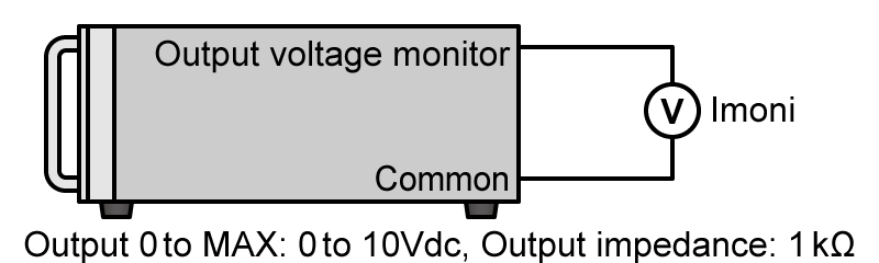
- Voltage monitor
-
Output voltage can be monitored by connecting a voltmeter or multimeter. For example, a monitor voltage of 0 to 10 V corresponds to the output voltage range from zero to full scale.
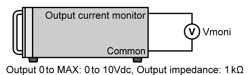
- Current monitor
-
Output current can be monitored and measured by connecting a multimeter or other voltmeter. For example, the monitor voltage of 0 to 10 V can be checked corresponding to the zero to full scale of the output current.
Remote sensing
- Voltage remote sensing
-
The voltage drop for the resistance due to the output cable can be compensated by connecting the remote sensing line to both poles of the load.
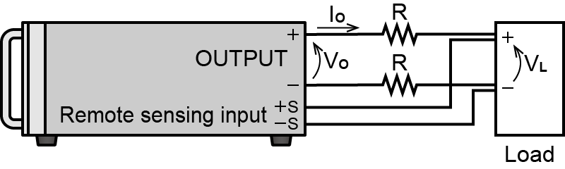
For more details, see our glossary entry: Remote Sensing
Status
Various status signals are provided via open collector outputs, and the status of the device can be monitored by connecting a multimeter or similar to the corresponding pin.
For more information, please see the FAQ: What is an open collector in a power supply?
- OUTPUT
-
Output ON state signal
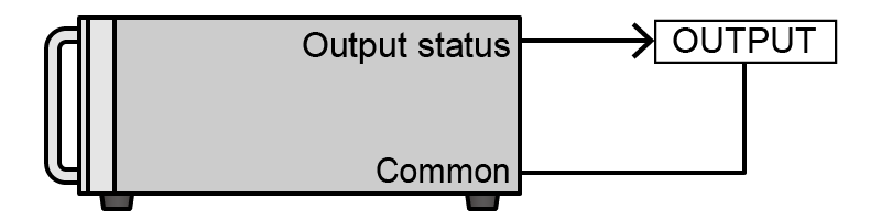
OUTPUT state, Open collector output is low impedance.
- Constant Voltage (CV)
-
Constant Voltage (CV) state signal
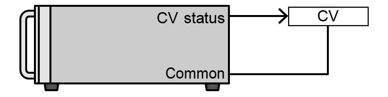
CV state, Open collector output is low impedance.
- Constant Current (CC)
-
Constant Current (CC) state signal

CC state, Open collector output is low impedance.
- Constant Power (CP)
-
Constant Power (CP) state signal
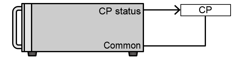
CP state, Open collector output is low impedance.
- Constant Resistance (CR)
-
Constant Resistance (CR) state signal

CR state, Open collector output is low impedance.
- Fault (FLT)
-
Various fault signals are available. The faults that can be detected vary by product. Fault signals include overvoltage protection, overcurrent protection, overpower protection, overtemperature protection, low AC input voltage, sense reverse connection, and interlock.
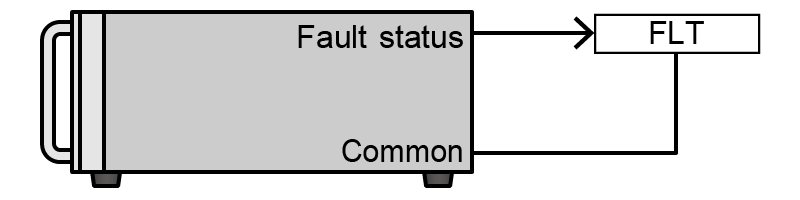
FLT state, Open collector output is low impedance.
- Overvoltage protection (OVP)
-
Overvoltage Protection (OVP) state signal
- Overcurrent protection (OCP)
-
Overcurrent Protection (OCP) state signal
- Overpower Protection (OPP) state signal
-
Overpower Protection (OPP) state signal
- Overtemperature protection (OTP)
-
Overtemperature Protection (OTP) state signal
- AC input failure (ACF)
-
AC Input Failure (ACF), low input voltage state signal
- Remote sense reverse connection failure
-
Remote sense reverse connection failure state signal
- Interlock (previous: Door switch OFF)
-
Interlock state signal (previous: Door switch OFF)
Terms
- Master/Slave
-
Master/slave is a function that allows the slave device to follow the operation of the master device. When the master device is controlled, the slave device follows and performs the same operation. By connecting the output terminals of the power supply in series or parallel, it can be controlled as a single power supply with increased voltage and current outputs.
- 1 mA current source
-
The 1 mA current source is a precision constant current source to control the set value of the output in resistance mode.
- Reference voltage
-
There are two types of reference voltages: internal and external. The internal reference voltage is output from the analog remote terminal, and the output can be controlled by connecting an external resistor. The other external reference voltage provides another reference power supply, and its output is input to the analog remote terminal to control the power supply output.
- Fail-safe mode
-
Fail-safe mode is a mode in which the logic of the control is inverted to ensure safety even in the event of a control wiring malfunction such as wire breakage.
- Common (COM)
-
Common is a shared connection point, which is a potential that serves as a signal reference. Or, it is the common ground.
Depending on the power supply, the common of the analog remote control terminal may be a positive common connected to the positive output terminal or a negative common connected to the negative output terminal.
For more information, please see Matsusada Precision's FAQ: "What does positive or negative common mean in analog remote control?"
- Return (RTN)
-
"Return" refers to the signal return path. It designates the terminal where the output current returns through the connected circuit.
- Relay
-
A relay is an electromagnetic relay, which is connected to a device to transmit a signal.
- TTL
-
TTL stands for Transistor-Transistor Level and represents a signal standard.
- Open collector
-
Open collector refers to the signal output method of electronic circuits. The collector of the transistor becomes the output terminal.
For more information about open collectors, please see Matsusada Precision's FAQ: "What is an open collector in a power supply?"
- Potentiometer
-
A potentiometer is a variable resistor used to adjust resistance continuously. It is widely used for analog signal control in remote operations to precisely set values. It is often referred to as a "pot" or "variable resistor."
- Output state auto recovery prevention (Previous: power failure protection)
-
The output state auto-recovery prevention function is a safety feature. It prevents the output from restarting automatically after a power failure occurs while the unit is active.
Appendix
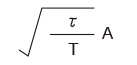
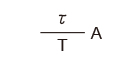
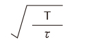
Waveform Conversion Table
- [Note]
-
- Crest factor = Peak value/RMS value
- Form factor = RMS value/Mean value
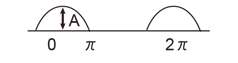
| Name | Wave | Shape | RMS | Crest factor | Form factor |
|---|---|---|---|---|---|
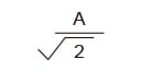
| Sine wave |
|
|
|
|
|
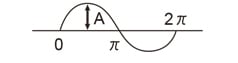
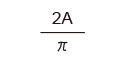
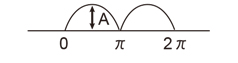
| Half-wave rectified wave |
|
|
|
2 |
|
| Full-wave rectifier wave |
|
|
|
|
|
| Triangular wave |

|
|
|
|
|
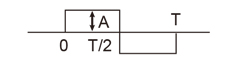
| Rectangular wave |
|
A | A | 1 | 1 |
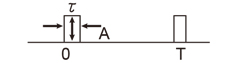
| Square wave |
|
|
|
|
|
Wire Gauge Index
| Gauge A.W.G |
Diameter [inches] |
Diameter [mm] |
Cross-sectional area [mm2] |
|---|---|---|---|
| 0000 | 0.4600 | 11.6840 | 107 |
| 000 | 0.4096 | 10.4038 | 85.0 |
| 00 | 0.3648 | 9.2659 | 67.4 |
| 0 | 0.3249 | 8.2525 | 53.5 |
| 1 | 0.2893 | 7.3482 | 42.4 |
| 2 | 0.2576 | 6.5430 | 33.6 |
| 3 | 0.2294 | 5.8268 | 26.7 |
| 4 | 0.2043 | 5.1892 | 21.1 |
| 5 | 0.1819 | 4.6203 | 16.8 |
| 6 | 0.1620 | 4.1148 | 13.3 |
| 7 | 0.1443 | 3.6652 | 10.6 |
| 8 | 0.1285 | 3.2639 | 8.37 |
| 9 | 0.1144 | 2.9058 | 6.63 |
| 10 | 0.1019 | 2.5883 | 5.26 |
| 11 | 0.0907 | 2.3038 | 4.17 |
| 12 | 0.0808 | 2.0523 | 3.31 |
| 13 | 0.0720 | 1.8288 | 2.63 |
| 14 | 0.0641 | 1.6281 | 2.08 |
| 15 | 0.0571 | 1.4503 | 1.65 |
| 16 | 0.0508 | 1.2903 | 1.31 |
| 17 | 0.0453 | 1.1506 | 1.04 |
| 18 | 0.0403 | 1.0236 | 0.823 |
| Gauge A.W.G |
Diameter [inches] |
Diameter [mm] |
Cross-sectional area [mm2] |
|---|---|---|---|
| 19 | 0.0359 | 0.9119 | 0.653 |
| 20 | 0.0320 | 0.8128 | 0.519 |
| 21 | 0.0285 | 0.7239 | 0.412 |
| 22 | 0.0253 | 0.6426 | 0.325 |
| 23 | 0.0226 | 0.5740 | 0.259 |
| 24 | 0.0201 | 0.5105 | 0.205 |
| 25 | 0.0179 | 0.4547 | 0.162 |
| 26 | 0.0159 | 0.4039 | 0.128 |
| 27 | 0.0142 | 0.3607 | 0.102 |
| 28 | 0.0126 | 0.3200 | 0.08 |
| 29 | 0.0113 | 0.2870 | 0.0647 |
| 30 | 0.0100 | 0.2540 | 0.0507 |
| 31 | 0.0089 | 0.2261 | 0.0401 |
| 32 | 0.0080 | 0.2032 | 0.0324 |
| 33 | 0.0071 | 0.1803 | 0.0255 |
| 34 | 0.0063 | 0.1600 | 0.0201 |
| 35 | 0.0056 | 0.1422 | 0.0159 |
| 36 | 0.0050 | 0.1270 | 0.0127 |
| 37 | 0.0044 | 0.1143 | 0.0103 |
| 38 | 0.0040 | 0.1016 | 0.00811 |
| 39 | 0.0035 | 0.0889 | 0.00621 |
| 40 | 0.0031 | 0.0787 | 0.00487 |
Related Technical Articles
Recommended products
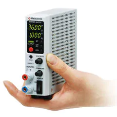
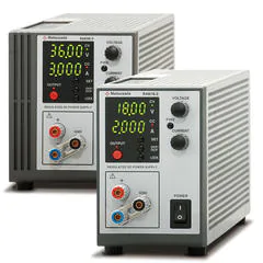
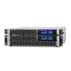
Matsusada Precision's high-performance DC power supplies