- Input Voltage
-
The input voltage range specifies the minimum and maximum voltages at which the power supply can operate while maintaining its rated output and performance specifications.
- Max
- Em
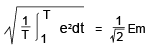
- RMS
-
E (rms) =
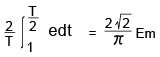
- Average
-
E (ave) =
AC inputs typically utilize single-phase or three-phase configurations, with three-phase used for higher power output models.
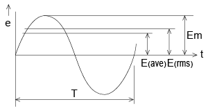
Fig. The sinusoidal AC voltage waveform
- Input Current
-
The input current is the amount of current input to a power supply expressed in RMS. Both series regulators and switching power supplies have capacitive rectifier circuits. This causes the input current waveform to not be sinusoidal but in a waveform as expressed below. The AC waveform of units with PFC (Power Factor Correction) will be sinusoidal.
Input current (rms) =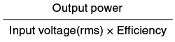
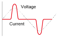
Fig. Input current waveform
- Input Power
-
Because power supplies have capacitive rectification circuits and smoothing circuits, the waveform of the input current will be distorted. The product of the input voltage (RMS) and the input current (RMS) is apparent power. The active power is the time-averaged product of the instantaneous voltage and current over a full cycle. Apparent power is the power that flows in the power supply, active power is the power consumed by the power supply. The gap between the apparent power and active power is the power not utilized, and is returned to the power grid.
- Apparent power = E (rms) x I (rms)
-
Active power =

- Efficiency
-
Efficiency is the ratio of output power to input active power. This value in the specification is at the rated output power. Efficiency is typically highest near the rated load and decreases at very light loads.
-
Efficiency (%) =
 x 100
x 100
- Power Factor
-
Power factor is the ratio of active power to apparent power. In the case of a power supply with capacitive input, the power factor is normally approximately 0.6. A power supply with PFC (Power Factor Correction) is approximately 0.9.
-
Power factor =

- Inrush Current
-
As switching power supplies apply capacitive input circuits, the inrush current can be from multiples of ten to multiples of hundreds of times that of normal operation. Inrush current is the crest value of current that flows when applying an input voltage to a power supply. In series regulators, an inrush current, typically 5 to 10 times the rated steady-state current, occurs. This is primarily caused by the charging of the secondary-side filter capacitor and potential transformer core saturation at power-on.
- Leakage Current
-
Leakage current refers to the current that flows through the protective ground conductor to earth. Limits are defined by regional safety regulations to prevent electric shock and ensure operator safety.
Current flowing through stray capacitance between the primary and secondary transformer windings, or through noise filter capacitors to the ground, constitutes leakage current. The diagram below illustrates a typical leakage current measurement circuit.
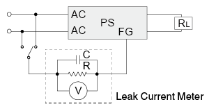
Fig. Leakage Current Measurement Circuit
- Line Regulation (Input Regulation)
- Line regulation is the fluctuation of the output voltage when the input voltage is changed within a specified range.
- Load Regulation
-
- Static Load Regulation
Static load regulation is the fluctuation of the output voltage when the load is changed from no load to the rated load.
- Dynamic Load Regulation
Also called transient response time, the dynamic load regulation is the output response time when the load is changed from no load to rated load quickly.
-
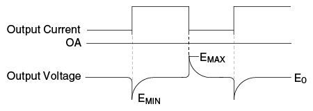
Fig. Dynamic load regulation
- Ripple
-
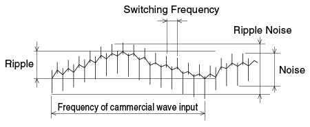
Ripple is a wave synchronized with the switching frequency and/or input frequency added to the output voltage. Ripple is usually expressed in peak-to-peak terms. When a capacitor is added to the output of a switching power supply, the component of the ripple synchronized with the switching frequency becomes smaller, but the composition synchronized with the input frequency remains the same. For series regulators, the ripple is only the noise synchronized with the input frequency.
- Ripple and Noise
-
Output noise is the combination of periodic ripple and random, high-frequency noise components superimposed on the DC output. It is often specified as PARD (Periodic and Random Deviation). Most switching power supplies use rectangular waveform inverters, so noise from switching transistors or output rectifier diodes is added to the output. Below shows the relation of ripple, output noise, and ripple noise. Series regulators, which lack high-frequency switching components, exhibit significantly lower noise compared to switching power supplies. Their output noise is primarily composed of ripple at the line frequency and its harmonics.
-
- Thermal Design (Heat Dissipation)
-
Since power supplies convert electrical energy, energy loss manifests as heat. Effective heat dissipation is a critical component of power supply design to ensure reliability.
- a. Natural Convection Cooling
-
Natural convection cooling dissipates heat via air movement caused by temperature differences, without using fans. Since this method relies on airflow, sufficient clearance around the unit is required. When installing inside an enclosure, ensure proper ventilation to prevent heat buildup. Effective exhaust ventilation is often more critical than intake size. Always install the power supply according to the specified orientation.
- b. Forced Air Cooling
-
Forced air-cooled power supplies use internal fans to generate airflow across components. For these units, maintaining the ambient temperature within specifications is typically sufficient. However, ensure that the intake and exhaust vents are never blocked to maintain proper airflow.
- Remote Control
-
Remote control functionality allows users to turn the power supply output on/off or adjust voltage/current settings using external signals. Control can be achieved via contact closures (relays, switches), transistors, or logic levels from integrated circuits. Logic polarity varies by model (e.g., LOW = ON, HIGH = OFF). Always verify the specifications in the datasheet before use.
- Isolation/Dielectric Strength
-
- Isolation Resistance
-
Isolation resistance is the resistance when applying a specified DC voltage between specified terminals.
- Dielectric strength
-
Dielectric voltage is a voltage that does not break the power supply or does not cause a spark discharge when a specified AC voltage is applied between specified terminals. To test the dielectric strength, increase the voltage gradually from 0 V so that rapid voltage change does not cause impulse voltage, or increase the voltage with a zero crossing switch.
- Operating Temperature
-
Operating temperature refers to the ambient temperature range in still air (unless forced air cooling is specified) where the power supply meets its specifications. Avoid installing the unit vertically or at extreme angles unless permitted. For forced air-cooled units, the operating temperature is the temperature of the air entering the intake. As a general rule, the lifetime of an electrolytic capacitor is reduced by 50% for every 10°C rise in temperature; therefore, operating at lower temperatures prolongs product life.
- Storage Temperature
-
Storage temperature is the ambient temperature at which the power supply can be safely stored without deterioration or performance of the power supply. Avoid storing power supplies in hot areas so as not to deteriorate the aluminum electrolytic capacitors within the power supply.
Recommended Products
Matsusada Precision's high-performance power supplies