


Types and Principles of Electron Microscope Lenses
This article details the lenses used in electron microscopes. As illustrated in the diagram below, the optical system consists of condenser lenses, objective lenses, intermediate lenses, and projector lenses. While they share the name "lens" with optical microscopes, their structure and operating principles differ significantly because they manipulate electron beams rather than light.
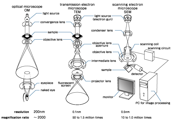
Of these, the lenses correspond to condenser lenses, objective lenses, intermediate lenses, eyepieces, and projector lenses. Compared to an optical microscope, the structure of the lens itself is different even if the same name "lens" is used because an electron beam is used as the light source.
Unlike optical lenses that use glass, electron microscopes employ electromagnetic fields to focus the electron beam. These components are known as "electron lenses" and are classified into two main types: electrostatic lenses and electromagnetic lenses. There are various types of electronic lenses, but what they have in common is that they utilize electromagnetic action.
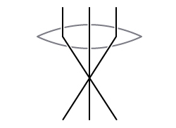
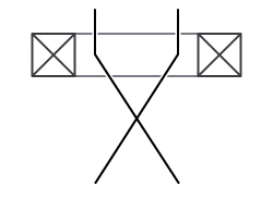
Figure: Comparison of Optical Lens and Electronic Lens
We introduce some examples of electronic lenses. An "electrostatic lens (electric field lens)" uses an electric field, especially an electrostatic field, to converge electrons. Electrostatic lenses utilize an electric field to focus electrons. A typical configuration involves a negatively charged central electrode positioned between two positively charged external electrodes. This arrangement creates an electric field that modifies the electron path.
To explain in a little more detail, electrons make a motion with constant acceleration in the electric field in the direction perpendicular to the equipotential plane. For example, between parallel electrodes, the equipotential plane is also parallel to the electrodes, so the electrons receive a force that moves between the electrodes in the shortest distance. Therefore, as shown in the figure below, the shape of the equipotential plane is controlled by devising the shape of the external electrode so that the electron can take the desired orbit.
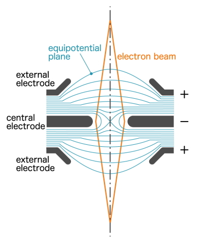
The figure is a cross-section and the actual shape should be axisymmetric (rotational symmetry). This type of lens has the advantage of operating even if the power supply voltage is somewhat unstable. However, there are problems such as large aberrations and the inability to shorten the focal length for high-energy electrons, so we have replaced the "electromagnetic lens" introduced below except for the part that accelerates and decelerates the electrons.
On the other hand, the "electromagnetic lens (magnetic field lens)" uses a magnetic field instead of an equipotential plane. Electromagnetic lenses utilize magnetic fields to control the electron beam. When electrons pass through a magnetic field, the Lorentz force acts perpendicular to both the direction of motion and the magnetic field lines, causing the electrons to spiral and converge toward the center.
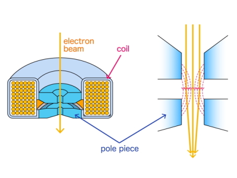
Basically, it is an electromagnet that uses a coil. But since the magnetic field strength is weak (the density of magnetic field lines is low), surround a coil with a material such as iron and create a magnetic pole that protrudes toward the center of the hole. This protruding magnetic pole is called a "pole piece", and the electron beam passes through the area surrounded by this pole piece.
At this time, the electrons passing through the center of the hole are not affected because they are traveling in the same direction as the direction of the magnetic field. But the electrons passing off the center of the hole are affected by the magnetic field and are gathered in the center while drawing a spiral orbit. This is the principle of focusing with an electromagnetic lens.
Since the degree of focusing is affected by the strength of the magnetic field, it is essential that the power supply voltage is stable.
Electromagnetic lenses are less affected by aberrations than electrostatic lenses, but they are still larger than optical lenses. Therefore, when using it, it is necessary to use only the electrons that have passed through the center of the lens as much as possible. The "objective lens diaphragm" placed under the lens plays this role. This cuts electrons from the periphery of the lens, which has large aberrations.
Positional Relationship between Sample and Lens
The placement of the sample relative to the objective lens is a critical factor in SEM design. There are two primary configurations: the "out-lens method" and the "in-lens method." One is the "out-lens method" in which the electron beam is placed after passing through the objective lens (in the case of SEM) or before (in the case of TEM). The other one is the "in-lens method" in which the electron beam is placed inside the objective lens (in the case of SEM only).
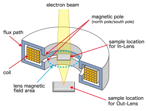
The in-lens method offers higher resolution, which shortens the focal length, but it cannot be used if the sample is affected by a magnetic field. In that case, the out-lens method, which is less affected by the magnetic field, will be used.
In addition, the in-lens method can only target samples of a size that can be placed inside the lens. On the other hand, with the out-lens method, it is possible to target samples that are larger than the in-lens method.
Therefore, it is necessary to use the out-lens method when the sample is large or affected by the magnetic field. And you use the in-lens method when the sample is small and not affected by the magnetic field. However, a "semi-in-lens (snorkel) method" objective lens was developed to largely mitigate this drawback of the in-lens method.
Since the sample is placed under the objective lens, it looks like an out-lens type, but the focal length can be shortened by devising the shape of the pole piece, so it is possible to obtain a resolution close to that of the in-lens method. The semi-in-lens method enables high-resolution observation of even large samples.
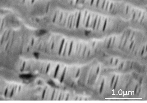
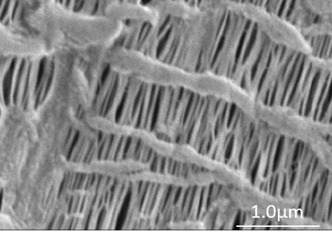
Figure: Image Comparison between Out-lens Method and Semi-in-lens Method
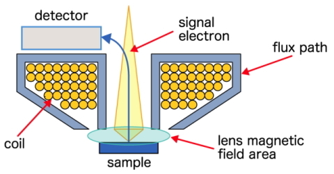
In addition, in the case of the out-lens method, there is a method of moving the detector closer to the sample for increasing the resolution. In this case, the out-lens acts as an obstacle to detector insertion. Therefore, it is necessary to increase the focal length, and the advantage of bringing the detector closer is lost.
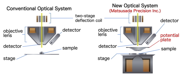
Matsusada Precision addresses these optical challenges with the Precision SEM3500 and SEM5600 systems. These models feature a specialized optical system that incorporates a "bottom lens" below the sample, in addition to the standard top lens. This design allows the detector to be positioned closer to the sample, improving resolution while maintaining a short focal length because the lens is under the sample. With the bottom lens, it is possible to increase the resolution.
Related Technical Articles
Recommended products
Matsusada Precision manufactures precision high-voltage power supplies for scanning electron microscopes.


Reference (Japanese site)
- Japanese source page 「電子顕微鏡(SEM)技術解説シリーズ② 電子顕微鏡のレンズについて」
(https://www.matsusada.co.jp/column/sem2.html) - 電子顕微鏡の原理
(https://www.jaima.or.jp/jp/analytical/basic/em/principle/) - 走査電子顕微鏡(SEM)の原理と応用
(https://www.jaima.or.jp/jp/analytical/basic/em/sem/) - 88年の常識を覆す画期的な電子顕微鏡を開発
(https://www.jst.go.jp/pr/announce/20190524/index.html) - 走査電子顕微鏡の原理と応用(観察,分析)
(https://www.jstage.jst.go.jp/article/jjspe/77/11/77_1021/_pdf)