Basics of Voltage Measurement
Voltage measurements are performed to verify the proper operation of electrical equipment and to inspect circuits. When measuring voltage, the voltmeter terminals must be connected in parallel with the component or circuit being measured.
Standard voltmeters or multimeters can easily measure voltages in the range of 1 V to 10 V, such as those found in general electronic circuits or consumer electronics. However, measurements involving high voltage or extremely low voltage require specialized equipment and techniques to ensure safety and accuracy.
How to measure high voltage (1000 V or more)
When measuring a high voltage of 1000 V or higher, you cannot measure it directly with a standard measuring instrument. High voltage carries sufficient energy to damage or destroy standard measuring instruments. Furthermore, the risk of electric discharge poses a severe shock hazard, necessitating extreme caution.
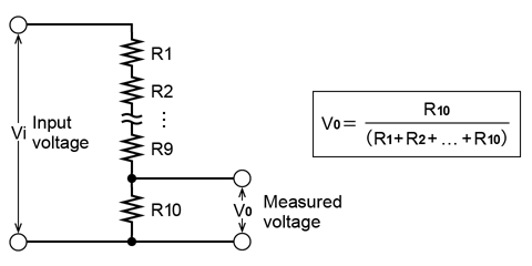
The fundamental principle of high-voltage measurement is to connect a high-value resistor in series with the measuring instrument. The voltage across the series of resistances is proportional to the magnitude of each resistance according to Ohm's law. The voltage applied to the voltmeter will be distributed if you connect a voltmeter and a high resistance in series.
For example, if the ratio of the connected resistance to the internal resistance of the measuring instrument is 9 : 1, the voltage applied to the resistance and the measuring instrument will also be 9 : 1. Compared to the state where no resistor is connected, the voltage applied to the measuring instrument is 1 / 10. This method is called voltage division, and there are the following methods for measuring high voltage using this mechanism.
The voltage divider (high voltage divider)
The voltage divider has a circuit built into the housing, an input terminal, and a measurement terminal. Also called a high-voltage divider, the basic circuit diagram of the voltage divider is as follows. While primarily used for DC voltage measurement, this method can also measure AC voltage at commercial power frequencies (50 Hz or 60 Hz).
Note that the voltage divider may generate heat during use, so you must be aware of the resistance value changes due to heat. It is also necessary to consider the voltage divider's resistance and the voltmeter's input resistance when making measurements. Since it handles high voltage, be careful to prevent current leakage caused by dirt or foreign matter adhering to the terminals.
Multiplier
Since the principle of the multiplier is the same as that of the voltage divider, the precautions for use are also the same. However, the voltage divider can measure AC voltage in some frequency bands, but the multiplier can only measure DC voltage.
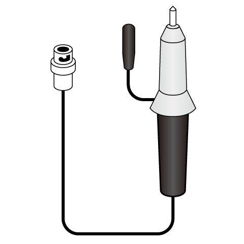
High voltage probe
High voltage probes include high voltage multimeter probes, high voltage oscilloscope probes, and high voltage differential probes. Generally, high voltage probes are high voltage divider probes with high voltage resistors inside.
For example, there are various types of probes used when measuring voltage waveforms with an oscilloscope, including those that can accurately measure high-frequency signals and those that reduce the impact on the measurement target. Among these, the probe that is compatible with high voltages is the high-voltage oscilloscope probe.
High voltage probes have different measurable voltages depending on the frequency. Therefore, be sure to check not only the maximum input voltage but also the frequency and the voltage that can be applied.
When measuring a high AC voltage, there is also a method of changing the voltage using the induced electromotive force of the coil.
Examples of high voltage probes
- Fluke high voltage probes for multimeters
(https://www.fluke.com/en-us/products/accessories/probes) - Tektronix high voltage probes for oscilloscopes
(https://www.tek.com/en/products/oscilloscopes/oscilloscope-probes/high-voltage-probe-single-ended) - Tektronix high voltage differential probes
(https://www.tek.com/en/products/oscilloscopes/oscilloscope-probes/high-voltage-differential-probes)
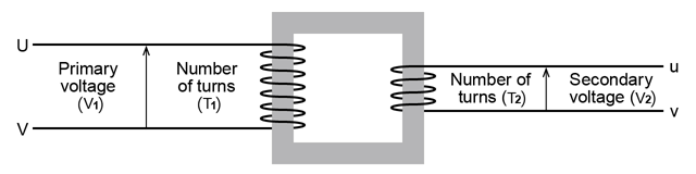
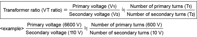
VT (Voltage Transformer)
VT (Voltage Transformer) is a device that converts the high voltage of an AC circuit into a voltage that is easy to measure. Previously it was called PT (Potential Transformer). The basic structure of the VT is the same as that of a transformer, as shown in the figure below. The input and output coils have a different number of turns and are wound around a donut-shaped iron core. The overhead wire voltmeters used in railway systems are an application of this principle. Please note that the overall accuracy can be affected by the specific voltmeter combined with the VT.
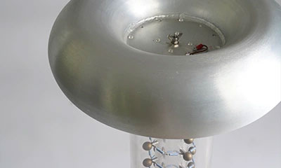
Static electricity measuring instrument (Electrostatic fieldmeter)
Static electricity is a typical example of electricity with high voltage. Since static electricity cannot be accurately measured when it comes into contact with a probe, etc., you must use a non-contact measuring instrument. A voltmeter for measuring static electricity is called an electrostatic voltmeter, and there are types such as surface electrometers and electrostatic fieldmeter.
This device measures surface static electricity. It operates based on the attractive or repulsive force between its electrodes and the charged object, which causes a pointer to move. A key advantage is that it can perform measurements independently, without the need for additional instruments.
High-voltage circuits can cause a discharge even if they are not in contact with each other or lead to a serious accident if there is an electric leakage. Safety measures such as proper grounding are also necessary when measuring high voltage. Follow the correct usage according to the specifications of the device.
How to measure low voltages (1 mV or less)
Standard measuring instruments may not offer sufficient accuracy for voltages below 1 mV. Unlike high-voltage measurements, low-voltage measurements often require signal amplification.
Since the signal level is extremely low, noise that is typically negligible can significantly impact measurement results. Therefore, noise suppression is a critical factor when measuring low voltages.
Noise that affects voltage includes external noise such as electromagnetic waves generated when the surrounding electrical equipment is switched on and off, as well as internal noise generated in the measurement circuit.
The points to remove noise in both direct current (DC) and alternating current (AC) are as follows.
In the case of DC
In circuits containing different metals, different temperatures at the junctions generate electromotive forces. This phenomenon is called Thermal Electromotive Force (EMF). Even in circuits that measure voltage, multiple types of metals are used in terminals, connectors, solders, and so on. Therefore, if there is a difference in the temperature of these joints, it will generate the thermal electromotive force.
To minimize thermal EMF, use conductors made of the same material whenever possible and avoid creating junctions of dissimilar metals. If a terminal is touched, allow it to return to ambient temperature before measuring. Maintaining a stable ambient temperature through air conditioning can also help.
In the case of AC
To mitigate this, it is advisable to use twisted-pair lead wires to cancel out electromagnetic interference. Additionally, proper shielding of the measurement environment is essential to prevent static electricity and external noise from affecting the signal.
In low voltage measurements, even small factors that are not usually a problem can become noise and affect the measurement. For example, the effect of static electricity cannot be ignored. If there is an electric charge such as the measurer's clothing nearby, it may cause noise.
It is also necessary to shield the measurement environment and prepare an environment where static electricity is unlikely to occur. Pay attention not only to the measuring equipment and circuits but also to the surrounding environment.
Reference (Japanese site)
- 日本電気計器検定所 テクニカルノート
(https://www.jemic.go.jp/wp-content/themes/jemic/gizyutu/c_5_001.pdf) - (株)島津総合サービス リサーチセンター 技術解説
https://www.shimadzu.co.jp/ssr/etc/ssrDlog/knowhow.pdf(Link rot) - TECH+ 「注意しないと命にかかわるぞ!! - 高電圧プローブ」
(https://news.mynavi.jp/article/oscilloscope2-6/) - 東京精電株式会社 「分圧器・倍率器」
http://www.tokyo-seiden.co.jp/seihinn/new/eh0010/ (non-HTTPS address) - 富士電機 「CT(変流器)・VT(計器用変成器)のワンポイントアドバイス」
(https://www.fujielectric.co.jp/technica/beans/05.html)
Recommended products
Matsusada Precision manufactures various power supply equipment, including high-voltage power supplies with safety in mind.