Bipolar Power Supply Selection Chart
Matsusada Precision offers a wide range of bipolar power supplies, also known as four-quadrant power supplies or bipolar amplifiers. Our lineup is categorized into two types: models with built-in function generators and bipolar amplifiers designed for external signal input. Use the selection chart below to find the ideal model based on output power, frequency bandwidth, and voltage requirements.
Bipolar Power Supplies (Built-in Function Generator)
Ideal for standalone operation, these models include a built-in function generator, enabling waveform output without external equipment. Suitable for evaluation, testing, and applications requiring simple waveform control.
| Series |
DJOPF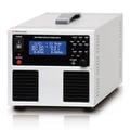
|
DOKF
|
DOPF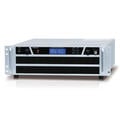
|
DOSF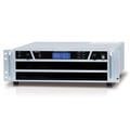
|
|
|---|---|---|---|---|---|
| Output Power | 50W, 60W | 400W | 150~2000W | 150~2000W | |
| Frequency Bandwidth | DC~30kHz | DC~120kHz | DC~30kHz | DC~200kHz | |
| Output Voltage | 5V | ±5V | |||
| 6V | ±6V | ||||
| 10V | ±10V | ±10V | |||
| 20V | ±20V | ±20V | ±20V | ±20V | |
| 25V | ±25V | ±25V | |||
| 30V | ±30V | ±30V | |||
| 40V | ±40V | ||||
| 45V | ±45V | ±45V | |||
| 60V | ±60V | ±60V | ±60V | ±60V | |
| 70V | ±70V | ||||
| 80V | ±80V | ±80V | |||
| 120V | ±120V | ||||
| 150V | ±150V | ||||
| 200V | ±200V | ||||
| 300V | ±300V | ||||
| Total models |
|
|
|
|
|
| Function Generator |
Built-in Type |
Built-in Type |
Built-in Type |
Built-in Type |
|
| Master/Slave Operation | -- |
Up to 3 units |
Up to 3 units |
Up to 3 units |
|
| Meter Indication |
|
|
|
|
|
| Sequence Function |
16 steps x 3 program |
1024 steps x 64 program |
16 steps x 3 program |
16 steps x 3 program |
|
| Communication |
Digital Option |
Digital Standard |
Digital Option |
Digital Option |
|
| Ripple | [CV mode] Less than 0.02% rms [CC mode] Less than 0.2% rms |
[CV mode] DOKF20-20: 2 mV Except DOKF20-20: 4 mV (typ.) [CC mode] 3 mA, Typical |
0.02 % rms | 0.02% rms | |
| Series |
DJOPF |
DOKF |
DOPF |
DOSF |
|
Bipolar Amplifiers (External Signal Input)
Designed to amplify external analog signals with high fidelity, these models are suitable for applications requiring precise waveform reproduction, such as piezo control, magnetic field generation, and dynamic testing.
| Series |
DJOP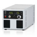
|
DHOP
|
DOP
|
DOS
|
DOL
|
DOA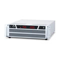
|
DOC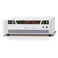
|
|
|---|---|---|---|---|---|---|---|---|
| Output Power | 50W, 60W | 225W, 240W | 150~2000W | 150~2000W | 270~640W | 75~300W | 50W, 100W | |
| Frequency Bandwidth | 30kHz | 100kHz | 30kHz | 200kHz | 15kHz | 1000kHz | 10kHz | |
| Output Voltage | 5V | ±5V | ||||||
| 6V | ±6V | |||||||
| 10V | ±10V | ±10V | ||||||
| 18V | ±18V | |||||||
| 20V | ±20V | ±20V | ±20V | ±20V | ||||
| 25V | ±25V | ±25V | ||||||
| 30V | ±30V | ±30V | ||||||
| 40V | ±40V | |||||||
| 45V | ±45V | ±45V | ±45V | |||||
| 60V | ±60V | ±60V | ±60V | ±60V | ||||
| 70V | ±70V | |||||||
| 75V | ±75V | |||||||
| 80V | ±80V | |||||||
| 120V | ±120V | ±120V | ||||||
| 150V | ±150V | ±150V | ||||||
| 200V | ±200V | |||||||
| 250V | 250V Option |
|||||||
| 300V | ±300V | |||||||
| 500V | ±500V | |||||||
| 1000V | ±1000V | |||||||
| 1000V or more | High Voltage Amplifiers | |||||||
| Total models |
|
|
|
|
|
|
|
|
| Function Generator | - | - | - | - | - | - | - | |
| Master/Slave Operation | - | - |
Up to 3 units |
Up to 3 units |
- | - | - | |
| Meter Indication |
Three-digit 2 screens |
Three-digit 2 screens |
Three-digit 2 screens |
Three-digit 2 screens |
Three-digit 2 screens |
Three-digit 2 screens |
Three-digit 2 screens |
|
| Sequence Function | - | - | - | - | - | - | - | |
| Communication | - | - | - | - | - | - | - | |
| Ripple | [CV mode] Less than 0.02% rms [CC mode] Less than 0.2% rms |
[CV mode] Less than 0.1% rms [CC mode] Less than 0.4% rms |
Less than 0.02% rms | Less than 0.02% rms | Less than or equal to 0.02% rms | [CV mode] 0.02% rms [CC mode] 0.2% rms |
||
| Series |
DJOP |
DHOP |
DOP |
DOS |
DOL |
DOA |
DOC |
|
Function Generator useful for bipolar amplifiers
External function generators for use with bipolar amplifiers. Recommended when advanced waveform control or higher resolution is required.