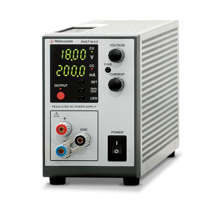
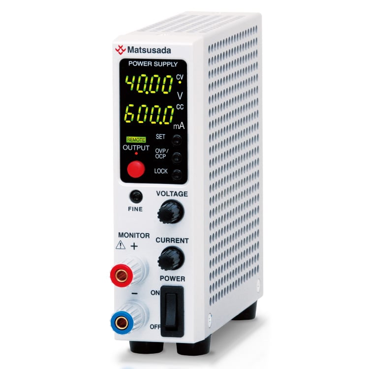
Ultra-Low Noise Performance with Linear Regulator Design
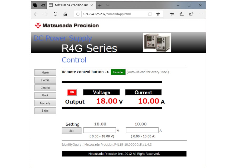
The R4G/R4GN series uses a linear regulator design to deliver high accuracy and ultra-low noise DC power. The series features a newly adopted high-resolution D/A and A/D converter, enabling precise settings and readouts on a 4-digit display.
Like our switching power supplies, such as the RK and REK series, the R4GN series features a negative common design. This facilitates remote control and easy integration into sequence control systems requiring a negative common ground.
Overvoltage and overcurrent protection are included as standard features. Additionally, digital communication functions are available, making the series suitable for a wide range of applications, from R&D experiments to automated production lines.
FEATURES AND BENEFITS
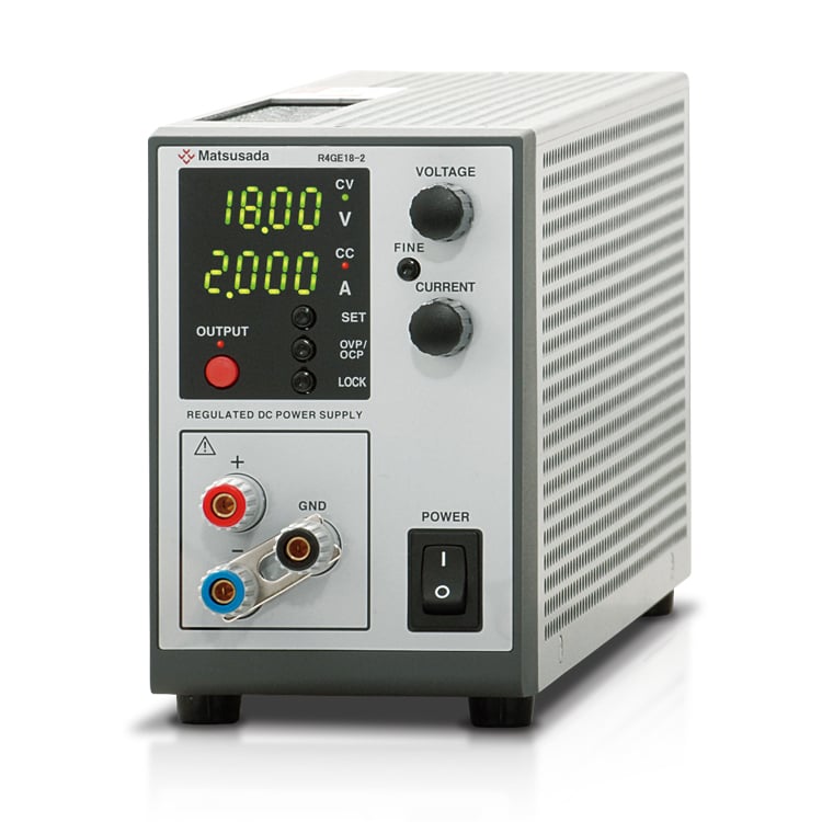
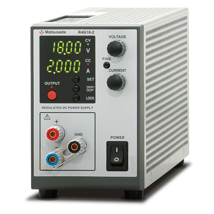
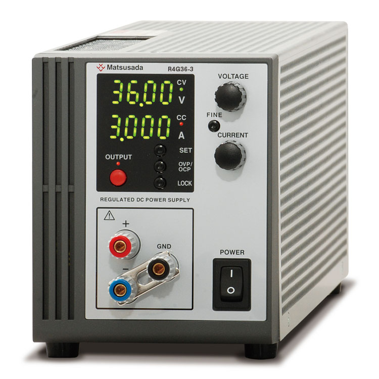
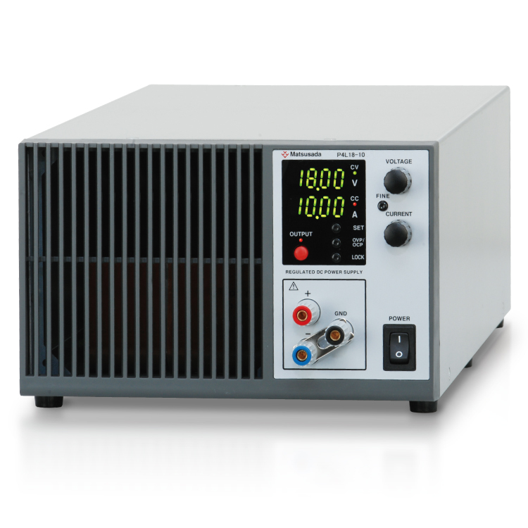
4-Digit Voltage and Current Display
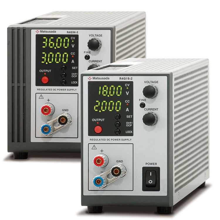
R4G
Voltage and current are displayed with 4-digit precision despite the compact size. This allows for detailed output control in steps of 1 mV and 0.1 mA.
R4GN
Voltage or Current is indicated with 4 digits despite its compact size. More extensive output control is available than ever before.
Ultra-low noise and High Speed Response
The linear regulator design ensures high-speed response with ultra-low ripple and noise. This series is ideal for applications where signal purity and stable power performance are critical.
Easy Integration into Automated Lines or Measuring System
R4G
Easily integrate into automated production lines or measurement systems by utilizing analog remote control, status outputs, and digital communication options.
R4GN
It is able to configure easily automation line or measuring system by utilizing options for analogue remote control, various status output, digital communication.
Comprehensive Standard Functions
Analogue remote control and multi-set in addition to overvoltage protection, overcurrent protection and key lock are included as standard equipment.
Applicable to Digital Interface Also
R4G
Digital interfaces can be built directly into the unit. This eliminates the need for expensive external communication controllers.
R4GN
Supports built-in digital interfaces. In addition to standard LAN, USB, and RS-232C, CC-Link is also available.
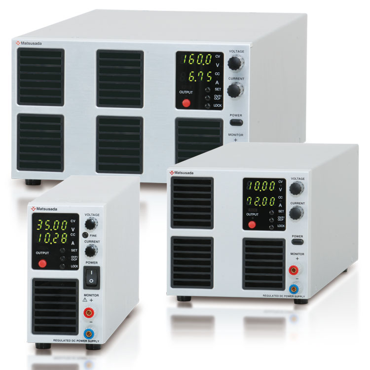
Fanless Cooling Design (Models up to 108 W)
It is quiet since it uses natural convection air cooling without a fan. This makes it ideal for applications that require silent operation, such as measuring the operating noise of test fan motors. In addition, it is a safe design in which the heat sink is not exposed from the case.
Negative common (R4GN series)
In many systems, particularly in Europe, the negative output of the power supply is mainly used as a common reference potential. The R4GN series is specifically designed with a negative common, making it ideal for systems requiring a common negative reference potential.
APPLICATIONS
For Research and Development (R&D) of Electronic Devices
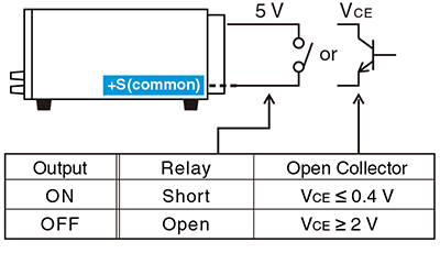
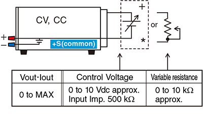
* The common side and the +output terminal are set to the same potential. Please use the floating control voltage without grounding, or setting the common of your equipment to the same potential. If you do not follow it, the power supply cannot be controlled properly and may cause malfunction. When using a multi-channel Programmable Logic Controller (PLC) or non-isolated PLC, note that there is a possibility of connection to other device grounds through the PLC.
Sink current 1mA
Logic of OUTPUT can be made reverse.
Output control
(Voltage, Current, Overvoltage protection, Overcurrent protection)
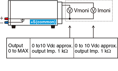
Output monitor
(Voltage, Current)
* Output control external signal should not be grounded but floating potential. positive output terminal and common become the same potential. The power supply can not be controlled or could be damaged if common is grounded via way of the customer's equipment. Please be aware that external control voltage signal could accidentally be connected to the ground of other equipment in case, for example, multi-channel, non-isolated PLC is in use.
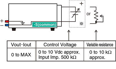
R4GN series
External output ON/OFF
* The common side and the -output terminal are set to the same potential. Please use the floating control voltage without grounding, or setting the common of your equipment to the same potential. If you do not follow it, the power supply cannot be controlled properly and may cause malfunction. When using a multi-channel Programmable Logic Controller (PLC) or non-isolated PLC, note that there is a possibility of connection to other device grounds through the PLC.
Sink current 1mA
Logic of OUTPUT can be made reverse.
Output control
(Voltage, Current, Overvoltage protection, Overcurrent protection)
Output monitor
(Voltage, Current)
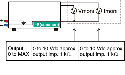
* The common side and the -output terminal are set to the same potential. Please use the floating control voltage without grounding, or setting the common of your equipment to the same potential. If you do not follow it, the power supply cannot be controlled properly and may cause malfunction. When using a multi-channel Programmable Logic Controller (PLC) or non-isolated PLC, note that there is a possibility of connection to other device grounds through the PLC.
R4G/R4GN series
Output of status
COMMON is floating with the output of an open collector for each COMMON. Isolation voltage 30 Vdc, sink current ≤ 5 mA
Power ON: ON at Power ON status
OUTPUT: ON at OUTPUT status
FLT: ON at abnormal status [ON for the status of OVP, OCP and Interlock.]
CV, CC: ON at CV or CC status
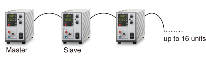
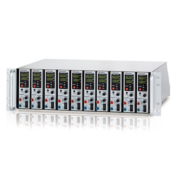
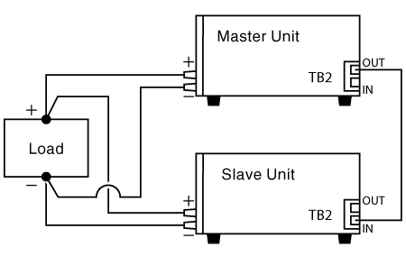
Parallel Operation by One Control
One master unit can control several slave units that are parallel connected. It is possible to increase output current by connecting more than 2 units of the same model power supply in parallel.
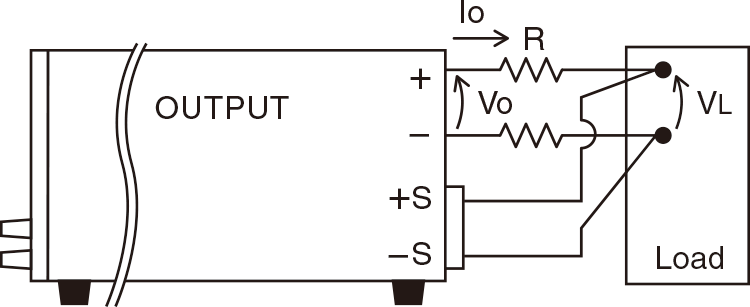
Remote Sensing
Prevent to degrade stability due to voltage drop (Vo-VL) by resistance (R) in output wiring or contact resistance. (up to 0.5 V)
(Except for R4G360-0.2, R4G650-0.1)
Digital Control Function (at selected various optional digital interfaces)
Control Function
Output ON/OFF setting
Display of various statuses (Output/Input/OVP/OCP/Interlock)
Digital control Max. 32 units
Package control multiple units hooked
Write Function
Setting output voltage/current
Percent mode *1, Voltage or Current mode *2
Setting OVP/OCP
Percent mode *1, Voltage or Current mode *2
Read Function
Measured output voltage/current
Percent mode *1, Voltage or Current mode *2
Setting output voltage/current
Percent mode *1, Voltage or Current mode *2
Setting OVP/OCP
Percent mode *1, Voltage or Current mode *2
Minimum setting unit for each model is one ten-thousandth (100.00%).
Minimum setting unit for each model is one count of the indicator.
Example of Connection and Operation
Using the same multiple units of the R4G/R4GN series, the output voltage and output current can be increased by connecting the outputs in series or parallel. Moreover, the synchronous operation and the master-slave operation with the -LGmb option are also available. Note: The common of the external Input/output control connector (TB1) is connected to the +output in the R4G series and the -output in the R4GN series. Do not connect the commons of the external Input/output control connector to each other.
Series connection
The total output voltage is up to 250 V.
The output voltage exceeding 250 V is unavailable in a series connection.
The output current will be the smallest value.
For the R4G/R4GN series, selecting the -LH high isolation voltage option increases the isolation voltage to 500 Vdc.
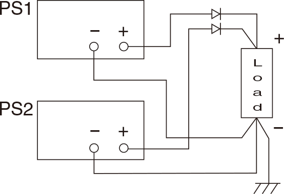
Parallel connection
Use the same value for voltage setting in parallel connection.
The output current is the sum of each current.
In order to prevent damage, set the OVP level of all the power supplies to the maximum.
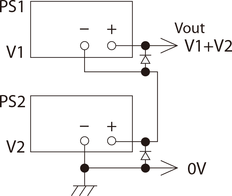
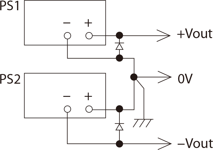
Split connection
+output and –output are available.
Specifications
Input voltage
120 Vac ±10%, 50/60 Hz, Single-phase
Output voltage control
[Local] Rotary encoder on front panel
[Analog remote] External control voltage 0 to 10 Vdc or external 10kΩ potentiometer
[Digital remote] Command (option)
Output current control
[Local] Rotary encoder on front panel
[Analog remote] External control voltage 0 to 10 Vdc or external 10kΩ potentiometer
[Digital remote] Command (option)
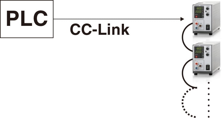
CC-Link interface port
A CC-Link master unit such as a PLC can control power supplies with CC-Link compatible with CC-Link ver1.10, which is possible to operate as a CC-Link device station. One unit occupies 2 stations, and a maximum of 32 units can be controllable.
Please refer to the CC-Link association web for CC-Link details.
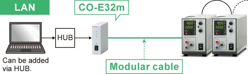
Multiple units can be simultaneously controllable by direct, HUB, or daisy chain connection.
-LGmb *1 *2
Digital Interface port
This is Matsusada Precision's proprietary digital communication port.
This interface has modular type IN and OUT ports to allow daisy-chain connection.
Combined with an adapter (sold separately). Multiple power supplies can be controlled at once.
Adapters for LAN, USB, RS-232C, RS-485, and GPIB are available so that you can choose a suitable communication interface.
One-control operation by master-slave connection is also possible.
-LGmb: Digital interface port + modular cable 2 meters
-LGmb(Mc0.15): Digital interface port + modular cable 0.15 meters
-LGmb(Mc0.5): Digital interface port + modular cable 0.5 meters
Optical Interface port
This option changes the standard interfaces to a built-in optical interface port.
By combining this option with an adapter for optical connection (sold separately), communication between the control device and the power supply can be controlled in an isolated state.
Be sure to select this option when using the product in the following environments.
-LGob: Optical interface port + optical cable 2 meters
-LGob(Fc5): Optical interface port + optical cable 5 meters
-LGob(Fc10): Optical interface port + optical cable 10 meters
-LGob(Fc20): Optical interface port + optical cable 20 meters
-LGob(Fc40): Optical interface port + optical cable 40 meters
Select the optional optical interface port (-LGob) when using this DC power supply under the following conditions.
Noisy environments such as factories (example: when motors or coils are used near loads or power sources).
If this power supply and your controller (PC or PLC) cannot be installed within 2 meters.
When there is a possibility of arcing or output short-circuit.
-LH
High isolation voltage
(only for models with a maximum output voltage of 80 V or less.)
With isolation voltage by ±500 Vdc, more R4G/R4GN series power supplies are available in series connection.
-LMi *1
Multiple Digital Interfaces
This interface comes with LAN, USB*, and RS-485 (Multi-drop) interfaces, providing flexible connectivity for various communication environments. (Simultaneous use of interfaces is not supported.)
Furthermore, an SCPI-compliant IVI driver is available for download from our website. This driver simplifies the development of control programs using a wide variety of languages such as LabVIEW, MATLAB, Python, C#, and Visual Basic.
*The USB port conforms to the USB Test and Measurement Class (USBTMC) protocol. If your application requires compatibility with the USB Communications Device Class (USB CDC), the RS-485 port can be used as a virtual COM port by using a third-party USB to RS-485 adapter.
-LRs *1 *2
RS-232C Interface port
Digital control is available with RS-232C. It is possible to hook 1 unit per 1 COM port equipped on a personal computer.
-LUs1 *1 *2
USB interface port
Digital control is available with USB. It is possible to hook 1 unit per 1 USB port equipped on a personal computer. If a number of USB ports equipped on the PC to be used is lacking, use a USB hub. But there is a case that the hub is not operated correctly.
OS for personal computers: Microsoft Windows Xp/Vista/7/8/10/11 Both of 32 bits and 64 bits are applicable
Microsoft and Windows are registered brands of Microsoft Corp. in the USA and others.
When ordering, please add the option symbols after the model name in alphabetical order. When selecting multiple options, remove “-L” from the second and subsequent option symbols and add them. Also, the option to change the input voltage (voltage) should be added last. Example: R4G18-2-LGob(Fc10)H(200V), R4G120-0.6-LCk(240V)
Additional accessories
AC Input Cable
The R4G/R4GN series comes with one AC power cord.
Standard
CABLE TYPE1
125 V/10 A
2.5 meters
Fixed length
-L(200 V)/-L(220 V) -L(240 V) option
CABLE TYPE3
250 V/10 A
2.5 meters
Fixed length
Sold separately
CABLE TYPE4
250 V/10 A
2.5 meters
Fixed length
Digital interface port
To use Matsusada Precision's digital interface, you need to prepare a digital interface adapter separately. The following interface adapters are available according to your controller port.
CO-E32m: LAN Adapter
USB-MET/CO-U32m: USB Adapter
CO-MET2-9: RS-232C (9 pin) Adapter
CO-MET2-25: RS-232C (25 pin) Adapter
CO-MET4-25: RS-485 (25 pin) Adapter
CO-MET2-9/CO-MET2-25/CO-MET4-25: The connector is D-sub type.
CO-G32m: GPIB Adapter (Scheduled for discontinuation in December 2028)
To use the optical interface, you need to prepare an optical interface adapter separately. The following interface adapters are available according to your controller port.
CO-E32: LAN to optical interface adapter
USB-OPT: USB to optical interface adapter
CO-OPT2-9: RS-232C (9 pin) to optical interface adapter
CO-OPT2-25: RS-232C (25 pin) to optical interface adapter
CO-OPT4-25: RS-485 (25 pin) to optical interface adapter
CO-G32: GPIB to optical interface adapter (Scheduled for discontinuation in December 2028)
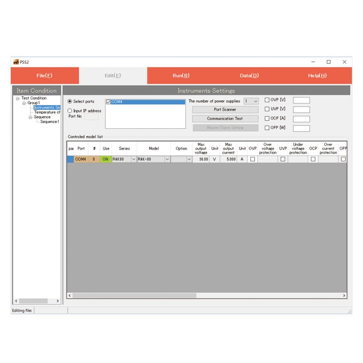
PSS2en series: Remote control, Test workflow design, and Data logging
PSS2en is the dedicated software that can actuate various power supplies, electronic loads, and digital controllers for power supplies manufactured by Matsusada Precision Inc. with a simple setup.
It is perfect for the aging test, the burn-in test and the withstand voltage test for electronic parts, and for the endurance test, intermittent/continuous operation test, or various simulation tests for electric components of automobiles. For details, refer to PSS2en page.
R4G/R4GT/R4GN series Instruction Manual (LMi Option)
Date: 2021-09-02 rev. 0.5 PDF (1,140 KB)
R4G/R4GT series Instruction Manual (LGmb, LGob, LUs1 and LRs in Option)
Date: 2023-08-07 rev.0.5 PDF (1,340KB)
R4G/R4GT series Instruction Manual (LCk option)
Date: 2023-3-14 rev.0.6 PDF (1,013 KB)
R4G series Instruction Manual (LNcn Option)
Date: 2020-06-16 rev 0.1 PDF (1,567 KB)
R4G series Rise and Fall Times
Date: 2020-10-29 rev. 01 PDF (210 KB)
USB driver (-LUs1 Option) for Windows 10, 11
Date: 2025-12-19 rev 2.12.36.20 ZIP(1,629KB)
USB driver (-LUs1 Option) for Windows XP, 7, 8, 8.1
Date: 2025-01-22 rev 1.7.6 ZIP (6,504 KB)
R4G/R4GT series LMi Option Driver (IVI Driver)
Last updated: February 10, 2020 rev.0.1 Zip File (8,754 KB)
RK/REK/R4G series USB Driver (LMi option guide)
Date: 2020-07-02 rev0.0 PDF (152 KB)
R4G series Outline Drawing (DXF, PDF)
Date: 2024-07-24 ZIP (3,454 KB)
On this website, we provide only the latest versions of information and instruction manuals for our products. Therefore, the newest versions of manuals on the website may differ from those that came with products you purchased in the past.


 Multiple units can be simultaneously controllable by direct, HUB, or daisy chain connection.