


What is electrical resistance?
Electricity has three elements: voltage, current, and resistance, and their combination determines how electricity flows.
The relationship between voltage, current, and resistance follows Ohm's law and is expressed as E (voltage) = I (current) × R (resistance).
Electrical resistance is one of these three elements of electricity, and its unit is the ohm (Ω).
The cause of resistance depends on the substance. In the case of metals, electricity is carried by conduction electrons present in the metal. However, the flow of electrons is impeded by collisions with the vibrating crystal lattice (phonons). This interaction creates electrical resistance in metals. This is the electrical resistance in metals.
On the other hand, insulators and semiconductors do not have conduction electrons. Electricity flows due to the transfer of charge between the valence band and the conduction band.
However, because the valence and conduction bands are not close together, electricity cannot flow unless energy is supplied to the valence electrons. This energy barrier, known as the band gap, creates high electrical resistance.
Resistance is the difficulty of electricity flow. Conductors such as metals have low resistance, while non-conductors such as rubber and leather have high resistance.
Generally, the power consumed by the resistor is released as thermal energy. Thus, for example, overvoltage or overcurrent can cause electronic equipment to heat up more than expected, which can lead to equipment burnout or fire. On the other hand, for the same voltage, a higher resistance value reduces the current flowing due to Ohm's law, resulting in lower power consumption.
What is a resistor?
If you want to add resistance to an electric circuit, use a resistor. A resistor is a part used to make it difficult for electricity to flow and is used to regulate the current flowing anywhere in a circuit or the voltage applied (meaning to send a signal or apply a voltage to a device).
There are the following types of resistors, and each type has its own characteristics.
- • Carbon film resistors
-
These are the most common and cost-effective resistors, available in a wide range of resistance values. They consist of a ceramic core coated with a carbon film. While they are affordable and easy to handle, their resistance value tends to change with temperature fluctuations.
- • Solid resistors
-
Solid resistors, also called carbon composition resistors (CCR) or solid composition resistors, are made of carbon powder mixed with resin. They are characterized by their ability to produce resistors with high withstand voltage and high resistance. Although durable and resistant to harsh conditions, carbon film resistors are more commonly used in recent years due to their lower accuracy and higher cost. Power ratings (wattage) include 1/4W (0.25W) and 1/2W (0.5W).
- • Metal Film Resistors
-
These are similar to carbon film resistors, but features ceramic covered with a metal such as nickel-chromium. In Japan, it is also called "kinpi". It has a small temperature coefficient and relatively high accuracy, but is somewhat more expensive. Power ratings (wattage) include 1/4W (0.25W), 1/2W (0.5W), and 1W.
- • Metal Oxide Film Resistors
-
It is a resistance wrapped with a film of metal oxide such as tin oxide on the surface of ceramic. Also called "Sankin" in Japan. Because the coating is an oxidized metal, it does not burn at high temperatures, so it is often used for medium power applications. Another advantage is that they are inexpensive relative to their power rating. However, accuracy and temperature characteristics are inferior to those of metal film resistors. Power ratings (wattage) include 1/2W (0.5W), 1W, 2W, and 3W.
- • Wirewound resistors, cement resistors, enamel resistors
-
A resistor consisting of a thin metal wire with high resistance, such as nichrome wire, wound around a ceramic bobbin or similar. A resistor coated or filled with cement is known as a wirewound cement resistor, and coated with enamel is an enamel wirewound resistor. It is characterized by low resistance but high power. The temperature coefficient is small and heat resistance is an advantage, but it has an inductance component due to its coil structure. Supports a wide range of power from 1/8W to 100W.
- • Network resistors
-
Multiple resistors are combined in one package. Various resistors are made in combination according to the purpose and application.
- • Semi-fixed resistors
-
Also called trimmer resistors or trimmer potentiometers, these are variable resistors whose resistance can be adjusted with a screwdriver via a small screw slot. They are typically used for fine adjustment or calibration in electronic circuits, and once set, the resistance value is not intended to be changed frequently.
Resistance is used in the following ways.
- • Current limiting resistor
-
A resistor is used to limit the current flow so that it does not become too high. For example, when lighting LEDs, connecting power directly to the LEDs will damage them. A resistor must be placed in series between the LED and the power supply, which is called a current-limiting resistor. If an LED with a forward voltage (Vf) of 2V is connected to a 5V power supply and operated at 10mA, a 300 Ω current-limiting resistor is required. R = (5V-2V)/0.01A = 300 Ω
- • Voltage divider circuit
-
A voltage divider circuit, also called a voltage divider, is a circuit or resistor used to divide a voltage. It is introduced in the basic calculation problem of electronic circuits, but when it is not possible to measure voltage directly such as in high voltage circuits, high voltage is measured using a voltage divider circuit. Photomultiplier tubes also require voltage dividers to be applied to multiple dynodes. In this case, a voltage divider is also used.
- • Pull-up resistor and pull-down resistor
-
These resistors are required when external signals such as switches and sensors are input to the microcontroller. For example, when connecting a microcontroller and a switch in a circuit, if the switch and the microcontroller are connected in series, when the switch is turned off, the input pins of the microcontroller are not connected anywhere.
This state is called high-impedance (Hi-Z) or floating. This condition makes the circuit susceptible to noise and surges, leading to reduced circuit stability and damage to the microcontroller.
To prevent this, a resistor is connected between the microcontroller's input pin and the voltage source (pull-up) or ground (pull-down). This ensures the input pin is maintained at a stable High or Low level, avoiding a "floating" state when the switch is open.Pull-up resistors 
Pull-down resistors 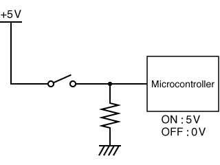
- • Termination resistor
-
A termination resistor, also called a terminator or termination, is an electronic component that is attached to the end of a communication cable, especially one with a high frequency.
In high-frequency signal cables for computer equipment, part of the waveform is reflected at the end of the cable.
Therefore, resistors must be used to dissipate the energy of the high-frequency signal. Termination resistors are used for this purpose.
Resistor color code reading and calculation for selection
The resistance value of the resistor can be read from the color code printed on its surface. The color printed on the far right of the resistor represents the tolerance, the second color from the right represents the multiplier, and the colors to the left represent the significant digits.
Since only tolerance values are assigned to silver and gold, it will be easier to find the resistance if you first find silver or gold to the right.
If silver or gold is not used, black, red, or brown will be on the right side.

| Color | Black | Brown | Red | Orange | Yellow | Green | Blue | Purple | Gray | White | Silver | Gold |
|---|---|---|---|---|---|---|---|---|---|---|---|---|
| Number | 0 | 1 | 2 | 3 | 4 | 5 | 6 | 7 | 8 | 9 | - | - |
| Numerical value | 100 | 101 | 102 | 103 | 104 | 105 | 106 | 107 | - | 10-3 | 10-2 | 10-1 |
| Tolerance | ±20% | ±1% | ±2% | ±0.05% | ±0.5% | ±0.25% | ±0.1% | ±10% | ±5% |
The following example demonstrates how to read the color codes.

4700 Ω = 4.7 kΩ
In this example, the yellow and purple on the left side are the resistance numbers, the second band from the right (red) is the multiplier, and the gold on the far right is the tolerance. Yellow is 4, purple is 7, and red is 2 with an tolerance of ±5% for gold, so this resistance is 4,700 Ω.

4700 Ω = 4.7 kΩ
In the following example, the resistance value is 4,700 Ω, but yellow is 4, purple is 7, black is 0, and brown is 1. The brown color on the far right represents a tolerance of ± 1%.
When selecting a resistor, first check the power rating of the resistor. As a rough guide, select a resistor with a derating power rating of at least twice the power dissipation of the circuit. The power consumed by the resistor is calculated as follows.
For example, for a 5V, 10mA circuit, the required resistance is 500 Ω according to Ohm's law. Therefore, the power consumed by the resistor is 0.01 x 5 = 0.05W. Therefore, select a resistor with a power rating of 0.1W or higher.
On the other hand, in a 12 V, 1.2 A circuit, the resistance would be 10 Ω. The power consumed by the resistor is 1.2 x 12 = 14.4 W. For such applications, select high-power components such as cement or enamel wirewound resistors that meet the required power rating.
While resistors may look similar, they come in various types with different resistance values and characteristics. Understanding resistor characteristics and color codes is essential for ensuring accurate component selection and circuit reliability.
Related Technical Articles
Reference (Japanese site)
- Japanese source page 「電気抵抗の役割と抵抗値の読み方」
(https://www.matsusada.co.jp/column/role_of_electrical_resistance.html) - 抵抗器とは? | 村田製作所 技術記事
(https://article.murata.com/ja-jp/article/what-is-resistor) - 抵抗器の基礎知識 | ROHM
(https://www.rohm.co.jp/electronics-basics/resistors/r_what1) - 抵抗器の基礎 | KOA株式会社
(https://www.koaglobal.com/product/library/resistor/basic/)