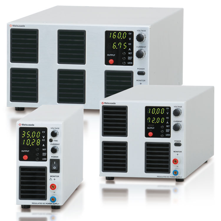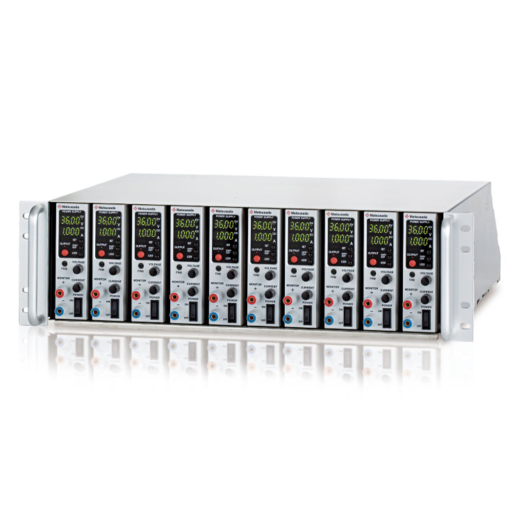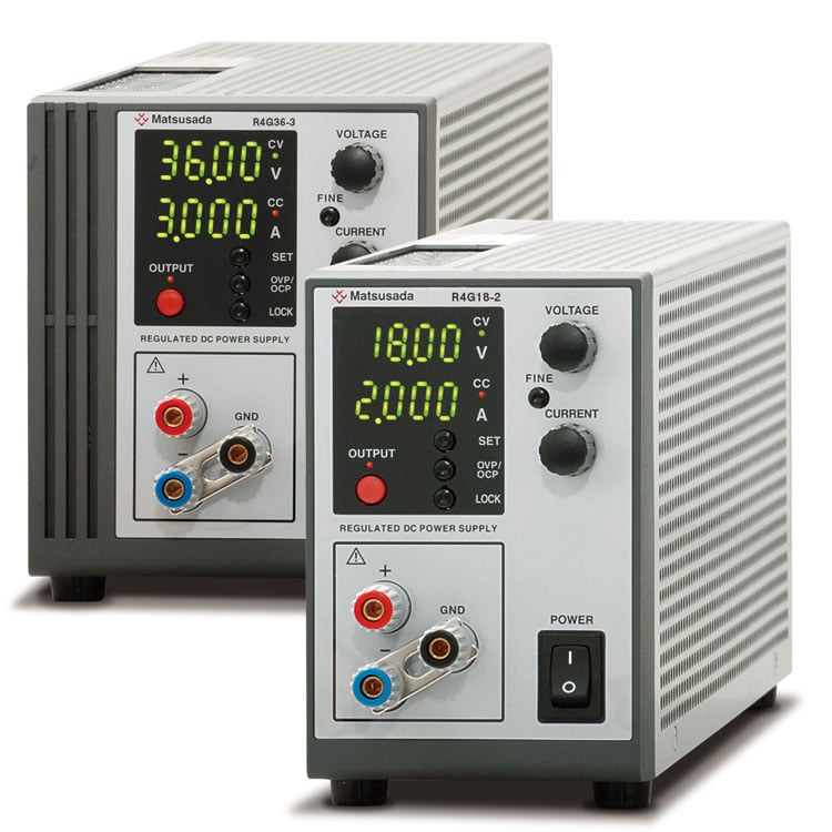
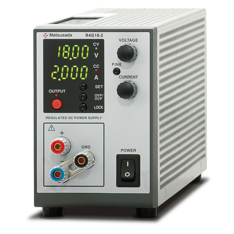
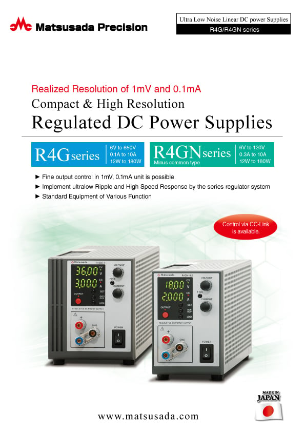
COMPACT AND HIGH RESOLUTION
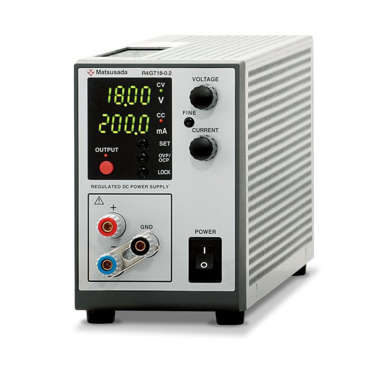
REGULATED DC POWER SUPPLY
- Max Voltage: 6V to 650V
- Max Current: 0.1A to 10A
- Max Power: 12W to 180W
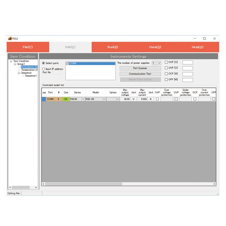
- Control via CC-Link is available.
ULTRA LOW NOISE WITH LINEAR REGULATOR SYSTEM
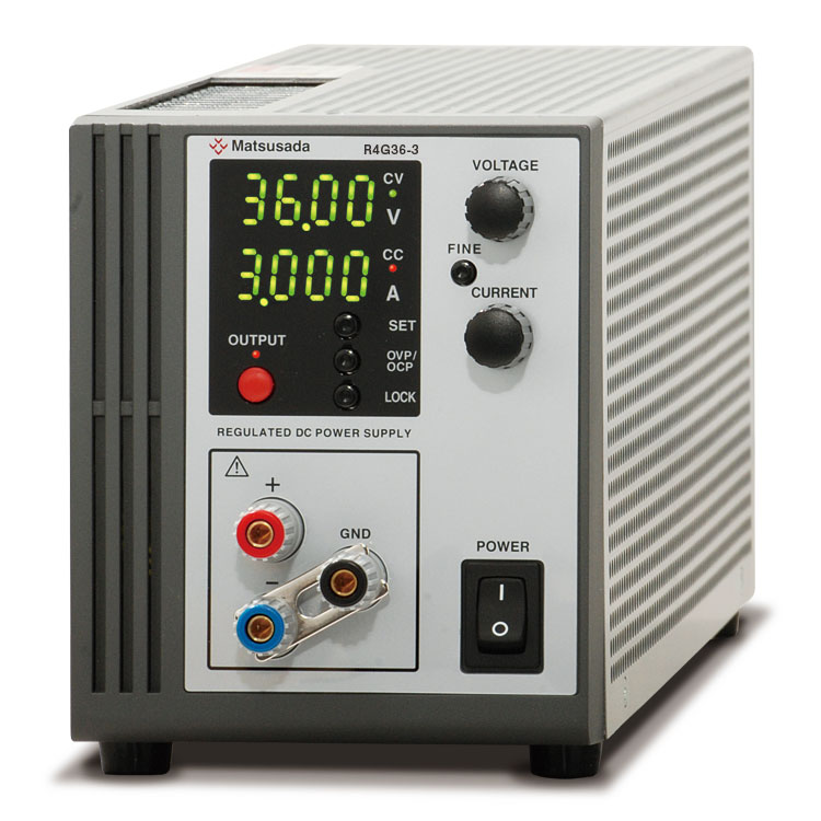
R4G/R4GN series are linear regulator system high accuracy and ultra-low noise DC power supply, so that enabled setting and reading out more fine output with a four digits indicator and a high-resolution D/A, and A/D converter adapted newly.
Overvoltage protection and Overcurrent protection are included as standard equipment, and digital communication function is available. They are applicable to a wide range, from experiments to automation lines.
FEATURES AND BENEFITS
- Voltage and / or Current displayed 4 digits indicator
- Voltage or Current is indicated with 4 digits despite of its compact size.
It has been possible to control output in more detailed unit as [1 mV] and [0.1 mA] than ever.
- Ultra low Ripple and High Speed Response
- High-Speed Response with ultra-low ripple and low noise by the linear regulator system.
It is best fit to applications that fundamental performance is important as DC power supplies.
- Ease of Formation of Automation Line or Measuring System
- It is able to configure easily automation line or measuring system by utilizing options for analogue remote control, various status output, digital communication.
- Standard Equipment of Various Function
- Analogue Remote Control and Multi-set in addition to Overvoltage Protection, Overcurrent Protection and Key Lock are included as standard equipment.
- Applicable to Digital Interface also
- It is able to built-in digital interface despite of series regulator system.
In addition to standard LAN, USB, and RS-232C, CC-Link (except for models in 360V or more) is also available.
- Silent Naturally-cooling System (108W Model and Smaller)
- Operation sound is silent as no cooling fan.
It is best fit for usage that its operation sound hinders measuring like as test of fan motor.
And it is the safety design so as not to expose the heatsink from the case.
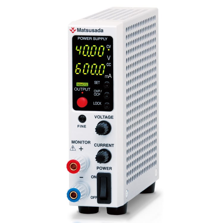
- Negative common (R4GN series)
- In European nations, the negative side of the power supply is mainly used as a common reference potential.
It is available with negative common type devices such as negative common type
APPLICATIONS
- Various Research and Development
- As a power source for automatic inspection systems, etc.
- For plating
- For Aging
- School Training Aid
Models
| Model | Maximum Output | ||
|---|---|---|---|
| Voltage | Current | Power | |
| R4G6-2 | 6 V | 2 A | 12 W |
| R4G8-5 | 8 V | 5 A | 40 W |
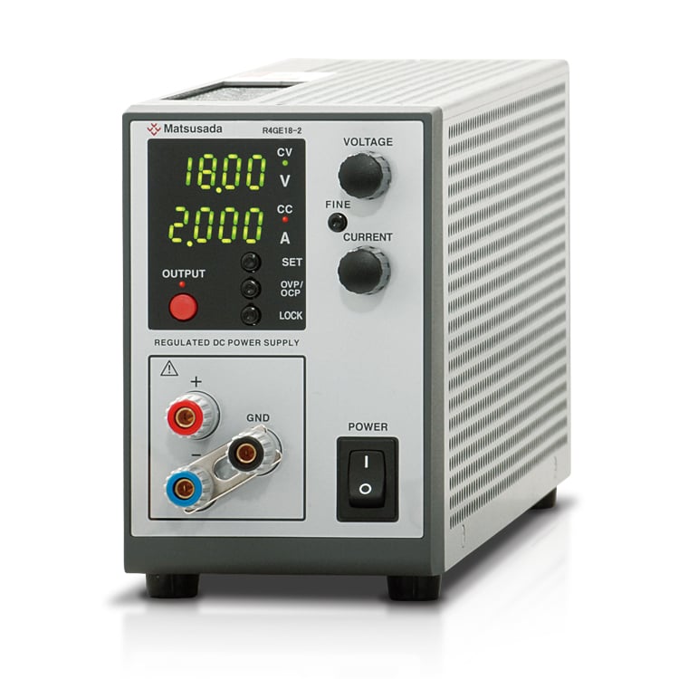
| R4G18-2 | 18 V | 2 A | 36 W |
| R4G18-3 | 3 A | 54 W | |
| R4G18-5 | 5 A | 90 W | |
| R4G18-10 | 10 A | 180 W | |
| R4G36-1 | 36 V | 1 A | 36 W |
| R4G36-3 | 3 A | 108 W | |
| R4G36-5 | 5 A | 180 W | |
| R4G45-2 | 45 V | 2 A | 90 W |
| R4G45-4 | 4 A | 180 W | |
| R4G60-1.2 | 60 V | 1.2 A | 72 W |
| R4G80-1 | 80 V | 1 A | 80 W |
| R4G120-0.3 | 120 V | 0.3 A | 36 W |
| R4G120-0.6 | 0.6 A | 72 W | |
| R4G160-0.45 | 160 V | 0.45 A | 72 W |
| R4G250-0.3 | 250 V | 0.3 A | 75 W |
| R4G360-0.2 | 360 V | 0.2 A | 72 W |
| R4G650-0.1 | 650 V | 0.1 A | 65 W |
| Model | Maximum Output | ||
|---|---|---|---|
| Voltage | Current | Power | |
| R4GN6-2 | 6 V | 2 A | 12 W |
| R4GN8-5 | 8 V | 5 A | 40 W |
| R4GN18-2 | 18 V | 2 A | 36 W |
| R4GN18-3 | 3 A | 54 W | |
| R4GN18-5 | 5 A | 90 W | |
| R4GN18-10 | 10 A | 180 W | |
| R4GN36-1 | 36 V | 1 A | 36 W |
| R4GN36-3 | 3 A | 108 W | |
| R4GN36-5 | 5 A | 180 W | |
| R4GN45-2 | 45 V | 2 A | 90 W |
| R4GN45-4 | 4 A | 180 W | |
| R4GN60-1.2 | 60 V | 1.2 A | 72 W |
| R4GN80-1 | 80 V | 1 A | 80 W |
| R4GN120-0.3 | 120 V | 0.3 A | 36 W |
| R4GN120-0.6 | 0.6 A | 72 W | |
Functions
External Analog Control
- R4G series
-
External Output ON/OFF
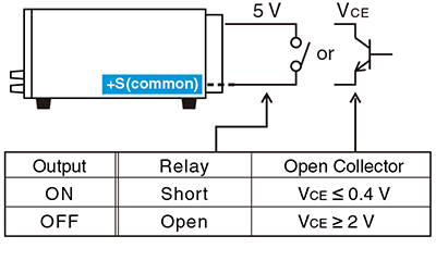
* The common side and the +output terminal are set to the same potential. Please use the floating control voltage without grounding, or set the common of your equipment to the same potential. If you do not follow it, the power supply cannot be controlled properly and may cause malfunction. When using a multi-channel Programmable Logic Controller (PLC) or non-isolated PLC, note that there is a possibility of connection to other device grounds through the PLC.
- Sink current 1mA
- Logic of OUTPUT can be made reverse.
Output Control
(Voltage, Current, Overvoltage protection, Overcurrent protection)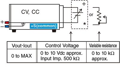
Output Monitor
(Voltage, Current)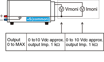
* Output control external signal should not be grounded but floating potential. + output terminal and common become same potential. Power supply can not be controlled or could be damaged if common is grounded via way of customer's equipment. Please be aware that external control voltage signal could accidentally be connected to the ground of other equipment in case, for example, multi-channel, non-isolated PLC is in use.
- R4GN series
-
External Output ON/OFF
 * The common side and the -output terminal are set to the same potential. Please use the floating control voltage without grounding, or set the common of your equipment to the same potential. If you do not follow it, the power supply cannot be controlled properly and may cause malfunction. When using a multi-channel Programmable Logic Controller (PLC) or non-isolated PLC, note that there is a possibility of connection to other device grounds through the PLC.
- Sink current 1mA
- Logic of OUTPUT can be made reverse.
Output Control
(Voltage, Current, Overvoltage protection, Overcurrent protection)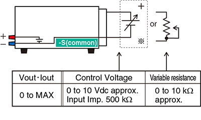
Output Monitor
(Voltage, Current)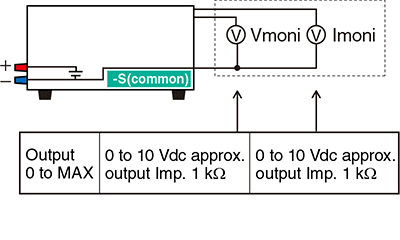
* The common side and the -output terminal are set to the same potential. Please use the floating control voltage without grounding, or set the common of your equipment to the same potential. If you do not follow it, the power supply cannot be controlled properly and may cause malfunction.When using a multi-channel Programmable Logic Controller (PLC) or non-isolated PLC, note that there is a possibility of connection to other device grounds through the PLC.
- R4G/R4GN series
-
Output of Status

COMMON is floating with the output of Open Collector for each COMMON.
Isolation voltage 30 Vdc, Sink Current ≤ 5 mA- Power ON: ON at Power ON status
- OUTPUT: ON at OUTPUT status
- FLT: ON at abnormal status
[ON for the status of OVP, OCP and Interlock.] - CV, CC: ON at CV or CC status
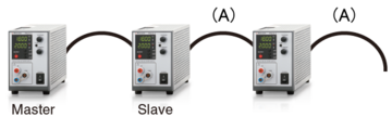
Parallel Operation by One Control
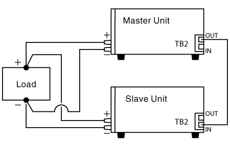
One master unit can control several slave units that are parallel connected.
It is possible to increase output current by connecting more than 2 units of the same model power supply in parallel.
Remote Sensing
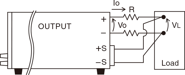
Prevent to degrade stability due to voltage drop (Vo-VL) by resistance (R) in output wiring or contact resistance. (up to 0.5 V)
(Except for R4G360-0.2, R4G650-0.1)
Digital Control Function (at selected various optional digital interface)
| Control Function |
Output ON/OFF setting Display of various Status (Output/Input/OVP/OCP/Interlock) Digital Control Max. 32 units Package Control Multiple Units Hooked |
|
|---|---|---|
| Write Function | Setting Output Voltage/Current | Percent Mode *1, Voltage or Current Mode *2 |
| Setting OVP/OCP | Percent Mode *1, Voltage or Current Mode *2 | |
| Read Function | Measured Output Voltage/Current | Percent Mode *1, Voltage or Current Mode *2 |
| Setting Output Voltage/Current | Percent Mode *1, Voltage or Current Mode *2 | |
| Setting OVP/OCP | Percent Mode *1, Voltage or Current Mode *2 | |
- Minimum setting unit for each model is one ten-thousandth (100.00%).
- Minimum setting unit for each model is one count of the indicator.
Example of Connection and Operation
Using the same multiple units of R4G/R4GN series, the output voltage and output current can be increased by connecting the outputs in series or parallel. Moreover, the synchronous operation and the master/slave operation with -LGmb option are also available.
Note: The common of the external Input/output control connector (TB1) is connected to the +output in the R4G series and the -output in the R4GN series. Do not connect the commons of the external Input/output control connector to each other.
Series Connection
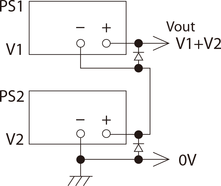
The total output voltage is up to 250 V.
The output voltage exceeding 250 V is unavailable in series connection.
The output current will be the smallest value.
Parallel Connection
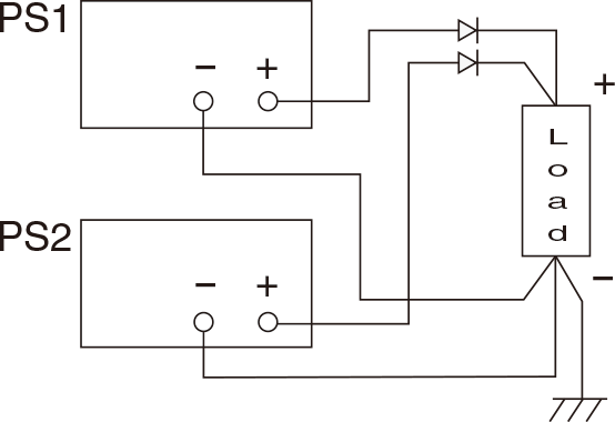
Use the same value for voltage setting in parallel connection.
The output current is the sum of each current.
In order to prevent damage, set the OVP level of all the power supplies to the maximum.
Split Connection
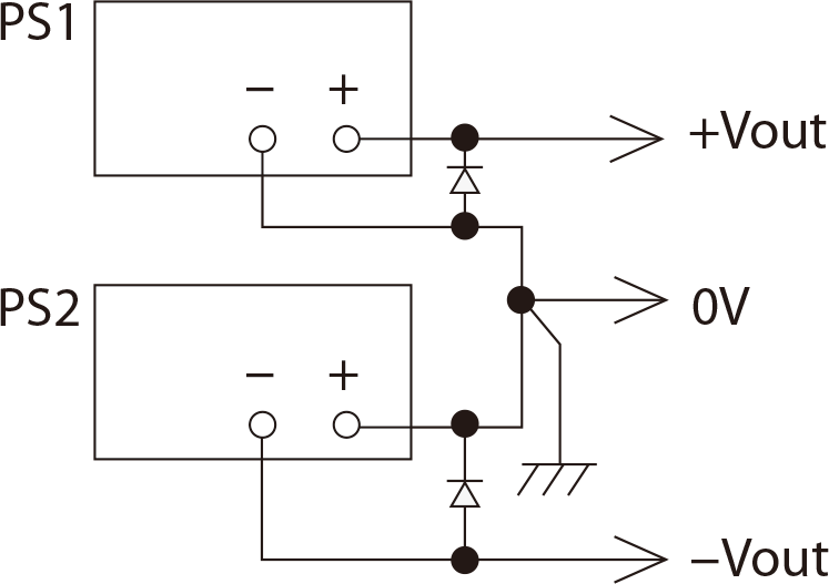
+output and –output are available.
Specifications
Options
- -LCk
-
CC-Link Interface Board *1 *3
CC-Link master unit such as PLC can control power supplies with CC-Link compatible with CC-Link ver1.10, possible to operate as CC-Link device station. One unit occupies 2 stations, maximum 32 units can be controllable.Please refer to CC-Link association web for CC-Link details.
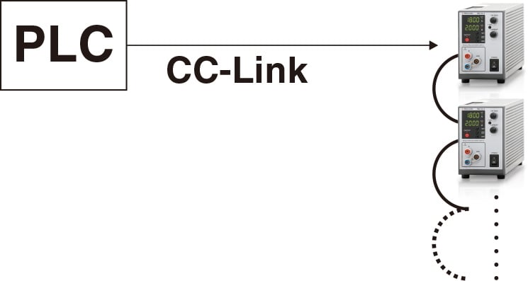 Multiple units can be simultaneously controllable by direct, HUB, or daisy chain connection.
- -LGmb
-
Digital Interface Board *1 *2
Enable digital control via LAN/USB/RS-232C/RS-485/GPIB as well as one control with Master/Slave.- -LGmb: Digital interface + modular cable 2 meters
- -LGmb(Mc0.15): Digital interface + modular cable 0.15 meters
- -LGmb(Mc0.5): Digital interface + modular cable 0.5 meters
Adapters (sold separately)
To use the digital interface, you need to prepare an digital interface adapter separately. The following interface adapters are available according to the communication method of your controller port.
- CO-E32m: Adapter for LAN
- Total 16 units can be connected to one CO-E32m.
- LAN cable is not provided.
- CO-U32m: Adapter for USB
- Total 16 units can be connected to one CO-U32m.
- USB cable is not provided.
- CO-MET2-9: Adapter for RS-232C (9 pin)
- Total 16 units can be connected to each CO-MET2-9.
- CO-MET2-25: Adapter for RS-232C (25 pin)
- Total 16 units can be connected to each CO-MET2-25.
- CO-MET4-25: Adapter for RS-485 (25 pin)
- Total 16 units can be connected to each CO-MET4-25.
- CO-G32m: Adapter for GPIB
- Total 16 units can be connected to one CO-G32m.
- GPIB cable is not provided.
For details, refer to CO/USB series datasheet.
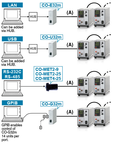 (A) CO-M cable
A two-meter cable is provided in each unit without interface option. If you need a longer cable, please consult with our sales staff.Master/slave
 ...up to 16 units
When noisy environment is presumed, the following -LGob option (optical interface) is required.
...up to 16 units
When noisy environment is presumed, the following -LGob option (optical interface) is required.
- -LGob
-
Optical Interface Board *1 *2
With optical communication, isolation control is performed. As complete isolation is performed by means of optical fiber, this enables advance prevention of erroneous operation involved with transient phenomenon caused by surges, inductive lightning, external noise, etc.- -LGob: Optical interface board + optical cable 2 meters
- -LGob(Fc5): Optical interface board + optical cable 5 meters
- -LGob(Fc10): Optical interface board + optical cable 10 meters
- -LGob(Fc20): Optical interface board + optical cable 20 meters
- -LGob(Fc40): Optical interface board + optical cable 40 meters
Select the optional optical interface board (-LGob) when using this DC power supply under the following conditions.
- Noisy environment including factories (Example: Motors or coils are used near power supplies and loads).
- Using with high voltage floating (more than 250 V).
- Installation distance of 2 meters or more between the DC power supply and a controller such as a computer, laptop, or Programmable Logic Controller (PLC).
Adapters (sold separately)
To use the optical interface, you need to prepare an optical interface adapter separately. The following interface adapters are available according to the communication method of your controller port.
- CO-E32: Adapter for LAN
- Total 32 units can be connected to one CO-E32.
- LAN cable is not provided.
- USB-OPT: Adapter for USB
- Total 32 units can be connected to one USB-OPT.
- USB cable is not provided.
- CO-OPT2-9: Adapter for RS-232C (9 pin)
- Total 32 units can be connected to each CO-OPT2-9.
- CO-OPT2-25: Adapter for RS-232C (25 pin)
- Total 32 units can be connected to each CO-OPT2-25.
- CO-OPT4-25: Adapter for RS-485 (25 pin)
- Total 32 units can be connected to each CO-OPT4-25.
- CO-G32: Adapter for GPIB
- Total 32 units can be connected to one CO-G32.
- GPIB cable is not provided.
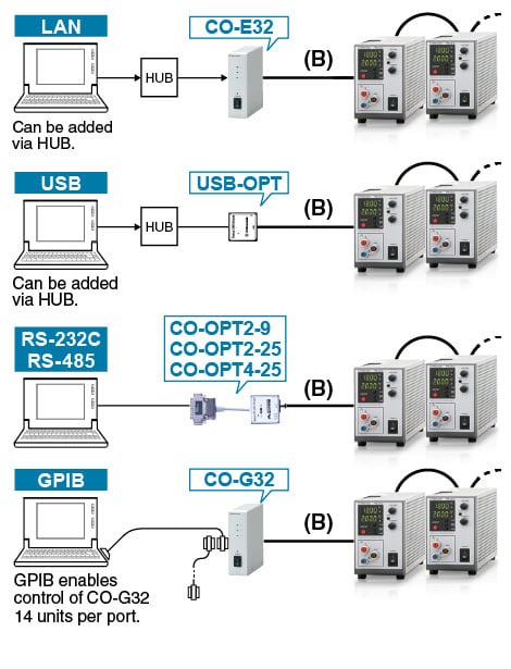 (B) Optical fiber cable
- -LH
-
High isolation voltage (only for up to 80 V models)
With isolation voltage by ±500 Vdc, more R4G/R4GN series power supplies are available in series connection.
- -LMi
-
Multi digital interface *1 *4
Digital control is available with LAN, USB (USB/TMC), RS-485 (Multi-Drop). (These interfaces cannot be used simultaneously. RS-485 supports FULL DUPLEX communication only.)
Also, the option employs IVI driver corresponding to SCPI command, enabling faster development of control program using programming languages including Labview, VisualBasic, and C#.
- -LRs
-
RS-232C Interface Board *1 *2
Digital Control is available with RS-232C. It is possible to hook 1 unit per 1 COM port equipped on your computer.
- -LUs1
-
USB Interface Board *1 *2
Digital Control is available with USB. It is possible to hook 1 unit per 1 USB port equipped on your computer. If the number of USB ports equipped on the computer to be used is lacking, use a USB hub. But there is a case that the hub is not operated correctly.Computer operating system: Microsoft Windows XP/Vista/7/8/10 Both 32 bits and 64 bits are applicable.Microsoft and Windows are registered brands of Microsoft Corp. in USA and other.
- -LZ
-
Handle for carrying
It is available for all the models. For more details, download the datasheet below.
- -L(200V), -L(220V), -L(240V)
- It is applicable to above input voltages other than standard 120 Vac.
- Either one of these options is selectable.
- For the detail function of optical interface, USB interface, RS-232C interface and digital interface, please refer to the datasheet of digital controller CO/USB series.
- Only for models of its maximum output voltage 360 V and lower.
How to Order
When ordering, add Option No. to Model No.in alphabetical order followed by the input voltage.
- Example:
- R4G18-2-LGob(Fc10)HNcn(200V)
- R4G120-0.6-LCkNcn(240V)
Accessories
| Standard | CABLE TYPE1 |  |
 |
125 V / 10 A | 2.5 meters Fixed length |
|---|---|---|---|---|---|
| Standard [-L(200 V) / -L(220 V) / -L(240 V) option] |
CABLE TYPE3 | |
 |
250 V / 10 A | 2.5 meters Fixed length |
| Sold separately | CABLE TYPE4 | |
 |
250 V / 10 A | 2.5 meters Fixed length |
Dimensions
Download
If you are unable to download a file
Please try the following solution.
- Please press Ctrl+F5 to clear the cache of your web browser and try again.
- Please restart your web browser and log in again to try again.
- Please change your web browser to another browser and try again.
- Restart the computer and try again.
- Please try again on a different computer.
-
R4G/R4GN series Datasheet
Date: 2023-07-21 rev.14
PDF (3,731 KB)
-
DC POWER SUPPLIES SELECTION GUIDE
Date: 2023-12-06 rev.00
PDF (1,202 KB)

-
How to Use DC Power Supplies
Date: 2024-03-05 rev. 08
PDF (1,467 KB)

-
R4G/R4GE series Basic Instruction Manual
Date: 2020-09-17 rev 0.0
PDF (375 KB)
-
R4GN series Basic Instruction Manual
Date: 2021-09-22 rev 0.0
PDF (433 KB)
-
R4G/R4GE series Instruction Manual
Date: 2021-09-29 rev. 08
PDF (1,531 KB)
-
R4GN series Instruction Manual
Date: 2023-08-11 rev.0.1
PDF (1,517 KB)
-
R4G/R4GT/R4GN series Instruction Manual (LMi Option)
Date: 2021-09-02 rev. 0.5
PDF (1,140 KB)
-
R4G/R4GT series Instruction Manual (LGmb, LGob, LUs1 and LRs in Option)
Date: 2023-08-07 rev.0.5
PDF (1,340KB)
-
R4G/R4GT series Instruction Manual (LCk option)
Date: 2023-3-14 rev.0.6
PDF (1,013 KB)
-
R4G series Instruction Manual (LNcn Option)
Date: 2020-06-16 rev 0.1
PDF (1,567 KB)
-
R4G series Rise and Fall Times
Date: 2020-10-29 rev. 01
PDF (210 KB)
-
R4G series USB Driver
Date: 2023-08-23 rev1.7.5
ZIP (6,617 KB)
-
R4G/R4GT series LMi Option Driver (IVI Driver)
Last updated: February 10, 2020 rev.0.1
Zip File (8,754 KB)
-
RK/REK/R4G series USB Driver (LMi option guide)
Date: 2020-07-02 rev0.0
PDF (152 KB)
The account registration is necessary for downloading
-
R4G/R4GN series Datasheet
Date: 2023-07-21 rev.14
PDF (3,731 KB)
-
DC POWER SUPPLIES SELECTION GUIDE
Date: 2023-12-06 rev.00
PDF (1,202 KB)
-
How to Use DC Power Supplies
Date: 2024-03-05 rev. 08
PDF (1,467 KB)
-
R4G/R4GE series Basic Instruction Manual
Date: 2020-09-17 rev 0.0
PDF (375 KB)
-
R4GN series Basic Instruction Manual
Date: 2021-09-22 rev 0.0
PDF (433 KB)
-
R4G/R4GE series Instruction Manual
Date: 2021-09-29 rev. 08
PDF (1,531 KB)
-
R4GN series Instruction Manual
Date: 2023-08-11 rev.0.1
PDF (1,517 KB)
-
R4G/R4GT/R4GN series Instruction Manual (LMi Option)
Date: 2021-09-02 rev. 0.5
PDF (1,140 KB)
-
R4G/R4GT series Instruction Manual (LGmb, LGob, LUs1 and LRs in Option)
Date: 2023-08-07 rev.0.5
PDF (1,340KB)
-
R4G/R4GT series Instruction Manual (LCk option)
Date: 2023-3-14 rev.0.6
PDF (1,013 KB)
-
R4G series Instruction Manual (LNcn Option)
Date: 2020-06-16 rev 0.1
PDF (1,567 KB)
-
R4G series Rise and Fall Times
Date: 2020-10-29 rev. 01
PDF (210 KB)
-
R4G series USB Driver
Date: 2023-08-23 rev1.7.5
ZIP (6,617 KB)
-
R4G/R4GT series LMi Option Driver (IVI Driver)
Last updated: February 10, 2020 rev.0.1
Zip File (8,754 KB)
-
RK/REK/R4G series USB Driver (LMi option guide)
Date: 2020-07-02 rev0.0
PDF (152 KB)
In this website, we provide only the latest version of information including instruction manuals as of our products. Therefore, the newest versions of manuals on the website might be not same as the ones of products you purchased in the past.