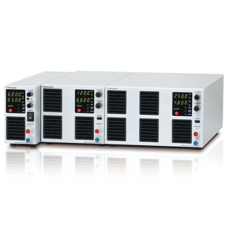
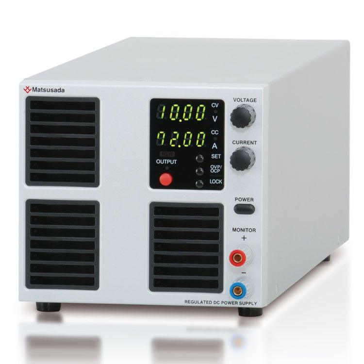
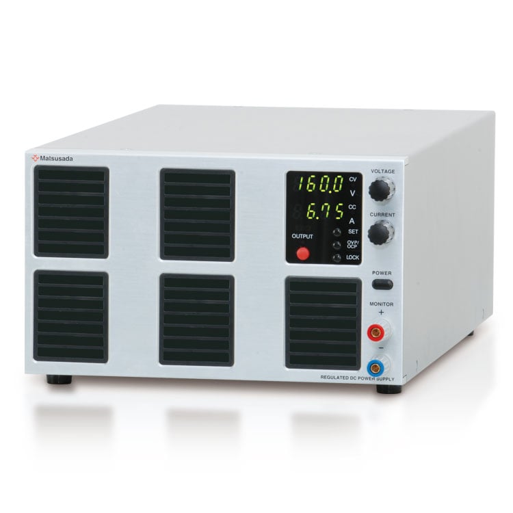
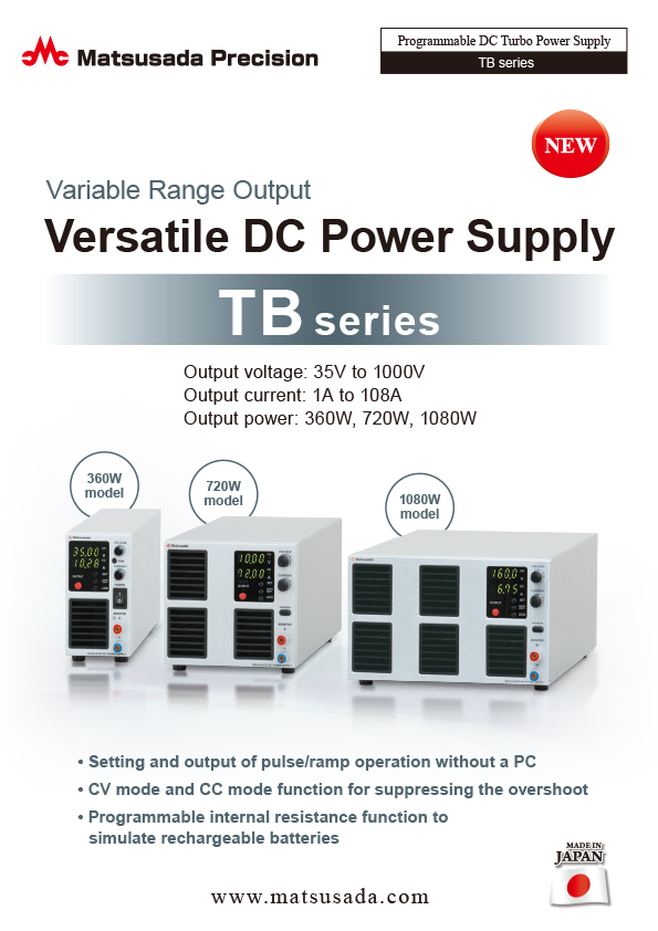
VERSATILE DC POWER SUPPLY
Variable Range Output
- Voltage range: 35 V to 1000 V
- Current: 1 A to 108 A
- Power: 360 W to 1080 W
- Pulse and Ramp sequence functions available
Wide-range output enabled by the "Turbo Function"
The TB series is a programmable DC power supply featuring a unique "Turbo Function" that provides a voltage and current coverage area three times wider than conventional DC power supplies of equivalent power rating.
All TB series models allow flexible voltage and current output within their rated power, eliminating the need to select different power supplies for varying requirements. A single TB unit supports a wide range of applications.
In addition to its wide output range, the TB series is engineered for exceptional performance. It features a power factor correction (PFC) circuit with a factor of 0.99, a fast and accurate four-digit display, and a precision rotary encoder. Its high energy efficiency also contributes to reducing CO2 emissions.
Digital communication via LAN, USB, RS-232C, RS-485, and GPIB is available with optional adapters, making it ideal for automated measurement and production line integration.
* An external adapter (sold separately) is required.
FEATURES
- Pulse/Ramp Sequence Operation: Create waveforms without a PC.
- Turbo Function: Achieves wide-range voltage and current output.
- CV/CC Priority Setting: Suppresses overshoot when the output is triggered.
- Variable Internal Resistance: Simplifies simulation of rechargeable batteries, solar cells, and fuel cells.
- Sink Current Suppression: Reduces reverse current flowing from the load to the unit, preventing voltage drops on the load when the output is OFF.
- Low-Noise Switching System: Optimized for research and development environments.
- Universal AC Input: Equipped with a power factor correction (PFC) circuit for global use.
MAIN APPLICATIONS
-
Evaluation test of electrical elements for automobile
Covered from 12 V to higher Voltage. By this one-unit -
Devices evaluation testing
For devices with different rated values -
Evaluation Testing with series/parallel connected power supplies
Suitable for battery, and capacitor evaluation with series/parallel connected power supplies -
Communication equipment inspection
To various tests for servers and rooters -
Power conditioners testing
For simulation of solar cell and fuel cell
Models
| Model | Maximum output | Ripple *1 (rms) | |||
|---|---|---|---|---|---|
| Voltage | Current | Power | Voltage | Current | |
| TB35V36A360W | 35 V | 36 A | 360 W | 8 mV | 30 mA |
| TB35V72A720W | 72 A | 720 W | 15 mV | 60 mA | |
| TB35V108A1080W | 108 A | 1080 W | 20 mV | 200 mA | |
| TB80V14A360W | 80 V | 14 A | 360 W | 7 mV | 16 mA |
| TB80V28A720W | 28 A | 720 W | 15 mV | 30 mA | |
| TB80V42A1080W | 42 A | 1080 W | 10 mV | 54 mA | |
| TB160V8A360W | 160 V | 8 A | 360 W | 15 mV | 10 mA |
| TB160V15A720W | 15 A | 720 W | 20 mV | 15 mA | |
| TB160V22A1080W | 22 A | 1080 W | 20 mV | 25 mA | |
| TB250V5A360W | 250 V | 5 A | 360 W | 20 mV | 10 mA |
| TB250V10A720W | 10 A | 720 W | 25 mV | 12 mA | |
| TB250V15A1080W | 15 A | 1080 W | 30 mV | 25 mA | |
| TB350V3A360W*2 | 350 V | 3 A | 360 W | 25 mV | 11 mA |
| TB350V6A720W*2 | 6 A | 720 W | 30 mV | 10 mA | |
| TB350V9A1080W*2 | 9 A | 1080 W | 35 mV | 16 mA | |
| TB650V1.6A360W*2 | 650 V | 1.6 A | 360 W | 30 mV | 6 mA |
| TB650V3.2A720W*2 | 3.2 A | 720 W | 35 mV | 7 mA | |
| TB650V4.8A1080W*2 | 4.8 A | 1080 W | 40 mV | 20 mA | |
| TB850V1.2A360W*2 | 850 V | 1.2 A | 360 W | 35 mV | 5 mA |
| TB850V2.4A720W*2 | 2.4 A | 720 W | 40 mV | 10 mA | |
| TB850V3.6A1080W*2 | 3.6 A | 1080 W | 45 mV | 15 mA | |
| TB1000V1A360W*2 | 1000 V | 1 A | 360 W | 40 mV | 5 mA |
| TB1000V2A720W*2 | 2 A | 720 W | 45 mV | 10 mA | |
| TB1000V3A1080W*2 | 3 A | 1080 W | 50 mV | 15 mA | |
- Ripple values range from 10% to 100% of the rated output.
- The front panel does not have monitor terminals.
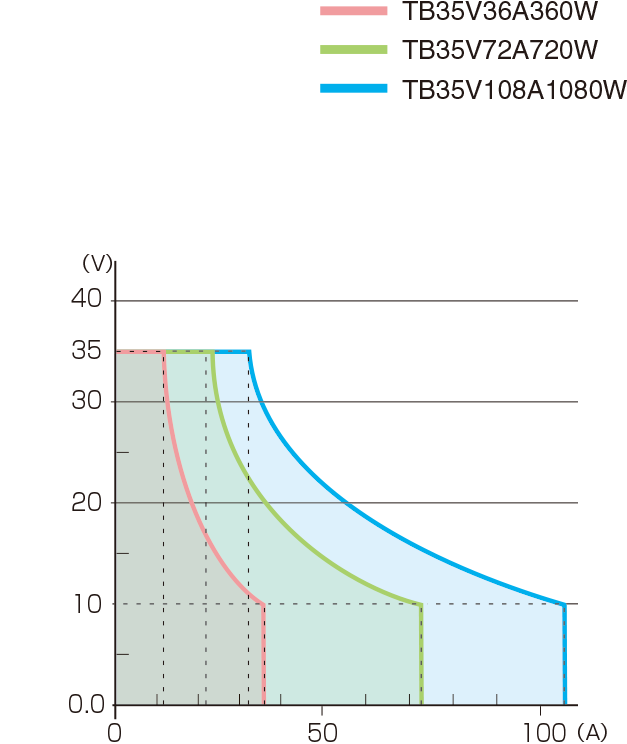
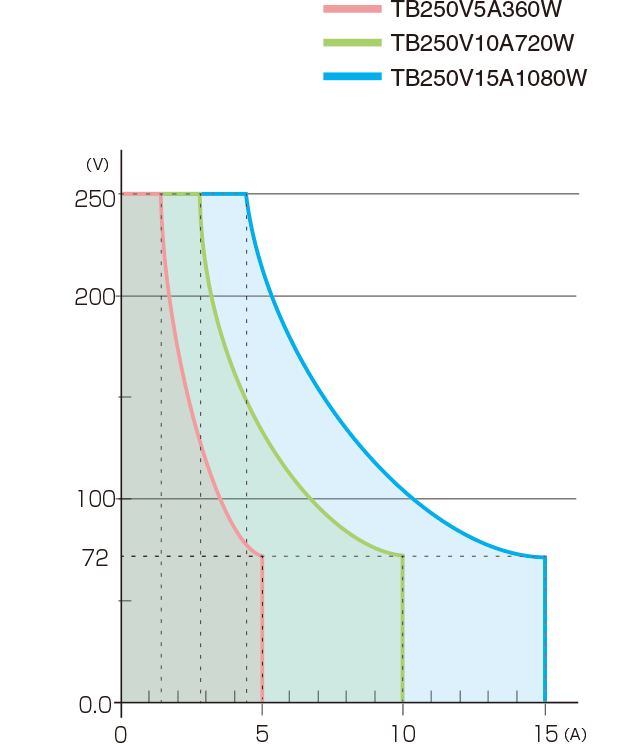
Functions
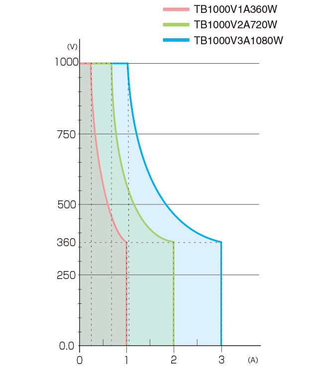
Images of Output Range
With the turbo function, a wide range of voltage and current output compared with conventional DC power supplies.
Pulse, Ramp, and Master Follow Functions
The following output control modes (A to D) are available to meet various testing requirements.
A. Pulse (Step) Sequence Function
The Sequence function lets you generate complex voltage and current patterns by automatically cycling through settings stored in memories a, b, and c. You can run the sequence continuously or for a specified number of cycles. By setting the duration of any step (a, b, c, or off) to 0.0, you can easily skip steps to create custom test patterns. This flexibility is ideal for product evaluation and reliability testing.
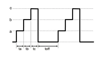
The parameters ta, tb, tc, and toff can be set to 0.0 s, or from 1.0 s to 99.9 h.
B. Ramp Function
The Ramp function provides linear control to gradually increase the output to a set voltage/current, or decrease it to zero. This feature is useful for applications that require a slow power-up or power-down.
* The ramp operation can be applied to: Voltage and Current, Voltage Only, or Current Only.
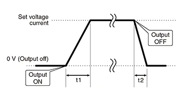
t1 and t2 can be set respectively in 0.0s to 999.9s.
C. Combined Sequence and Ramp
For advanced control, the Sequence and Ramp functions can be used together. This allows you to create complex profiles by smoothly ramping the voltage and/or current between the discrete steps defined in memories a, b, and c. The entire waveform can be run continuously or for a pre-set number of cycles, making it a powerful tool for various testing scenarios.
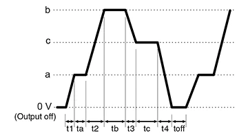
t1 and t2 can be set from 0.0 s to 999.9 s, while ta, tb, tc, and toff can be set to 0.0 s or from 1.0 s to 99.9 h.
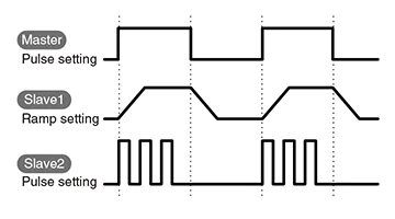
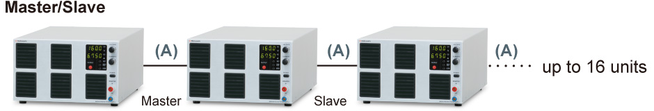
D. Master Follow (Tracking)
Master-follow is a function that allows a slave equipment to follow the output status of the master equipment in a master/slave connection. The output status of the master equipment is transmitted to the slave equipments to enable interlocked operation. The master and slave can be set to different modes of operation, allowing for complex testing.
* The Master Follow function is available only with Matsusada Precision's original digital interface.
- [NOTE]
- (1) This function cannot be used in conjunction with “Delayed Trigger Function”
- (2) Time accuracy in sequence operation is ±0.5%. Take care when using the product in long-term running operations.
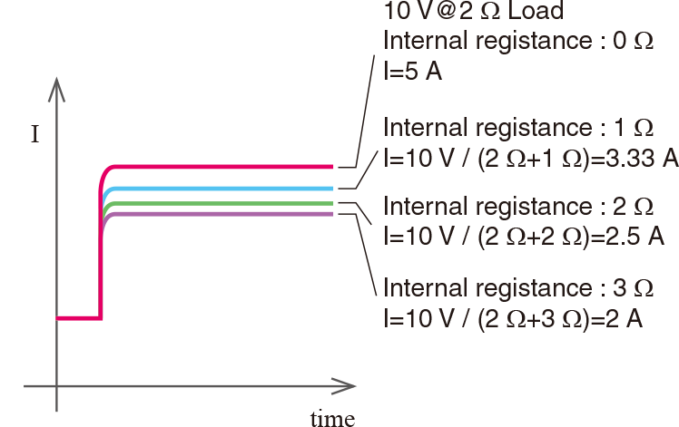
Variable Internal Resistance Function (in CV mode)
By setting the internal resistance value as any value, it causes a voltage drop due to load current.
This is the best fit for simulating batteries, solar cells/panels, and fuel cells.
(Programmable range of the internal resistance value is 0 Ω to rated voltage/rated current)
Function for Multi-setting
Three sets of voltage and current values can be stored in memory, in addition to the standard preset.
It is very useful for experiment to collect repeatedly data and inspection of products.
Two Modes for Lock
Either of two modes can be selected and set, "Full Lock," which locks all operations from the front panel, or "Normal Lock," which locks only output ON/OFF. (The above two modes can stop the output emergently with the power switch.)
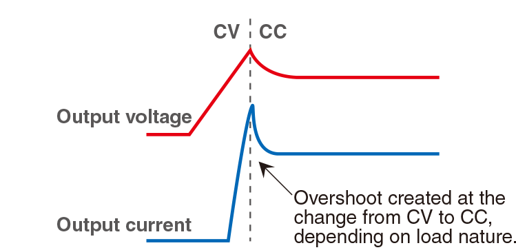
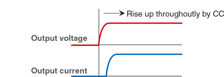
CC/CV Preferred setting
CV (Constant Voltage) or CC (Constant Current) preferred mode can be selectable. When a load is such as a diode whose resistance value can dramatically change at a certain point, an overshoot of current may take place if the power supply is triggered under CV mode.
The TB series can help suppress this overshoot by choosing the CC mode trigger as a preference. This feature is highly valued for lowering the risk of damaging expensive loads typically such as high-power laser diode modules.

Sink Current Suppression
When supplying power to loads with capacities like batteries and capacitors, the sink current suppression is used to reduce the reverse current flowing from the load to the unit in order to prevent a voltage drop on the load as the output is OFF or the set voltage is lowered.
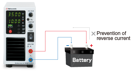
Note: Reverse current cannot be controlled and stabilized. Connect a dummy resistor or reverse current prevention diode when a load of the reverse voltage is equal to or higher than the rated voltage (inductive loads, regenerative motors, etc.).
Delayed Trigger Function
The delayed trigger function allows it to delay the time for output start and output stop, and work based on it during OUTPUT ON/OFF. The delayed trigger function can be used when 1 unit of TB is used, of course. The delayed trigger function can also be used when output voltage/output current are set individually by connecting several Matsusada Precision power supplies using master/slave connection terminal.
- This function can not be used with Function for Pulse & Ramp sequence and Master Follow together.
- Can be connected to up to 16 units.
- R4K-36 series, R4K-80 series, RK-80 series, RK series, and REK series.
- Only for slave-local. In the case of the slave remote control, the exact same model of power supply needs to be used. Also, in the case of slave-local, each output voltage and current can be set individually. In the case of slave-remote, output voltage, and current can be set with a one-control function in which each slave unit follows the master unit setting.
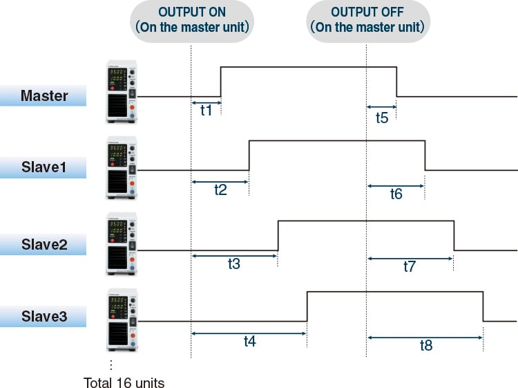
*t1 to t8 can be set in the range of 0.0 to 99.9 s.
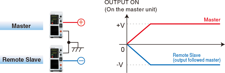
Dual Tracking and Multi-Output
Dual Tracking: By connecting two units in a master/slave configuration for positive and negative output, both outputs can be controlled simultaneously. The slave unit tracks the master unit's settings.
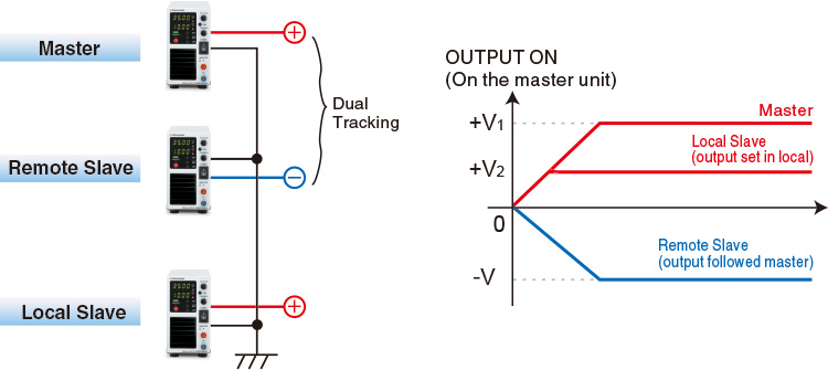
Multi-Output: This configuration combines local mode operation with dual tracking. Positive and negative outputs, along with any optional output voltages set on local slave units, are synchronized with the master unit's ON/OFF operation.
* As for dual tracking control, models at output voltage exceeding 250 V are not available with the function.
Dual Tracking
Multi Output
External Analog Control
The following functions are available. For details, download the datasheet below.
- External output ON/OFF
- Switching REMOTE/LOCAL
- Output monitor(Voltage, Current)
- Output control(Voltage, Current, Overvoltage protection, Overcurrent protection)
- Output of status
Digital Interface port
This is Matsusada Precision's proprietary digital communication port. This interface has modular type IN and OUT ports to allow daisy-chain connection. Combined with an adapter (sold separately). Multiple power supplies can be controlled at once. Adapters for LAN, USB, RS-232C, RS-485, and GPIB are available so that you can choose a suitable communication interface. One-control operation by master/slave connection is also possible.
Master-slave connections require all units to be the same model within the series.
If a noisy environment is expected, the -LGob optical interface port option is required.
Specifications
- Input voltage
- 100 to 240 Vac, 50/60 Hz, Single-phase
- Output voltage control
-
[Local] Rotary encoder on front panel
[Analog remote] External control voltage 0 to 10 Vdc or external 10kΩ potentiometer
[Digital remote] Command - Output current control
-
[Local] Rotary encoder on front panel
[Analog remote] External control voltage 0 to 10 Vdc or external 10kΩ potentiometer
[Digital remote] Command
Options
- -LEt *1
-
LAN Interface Port
Enables digital control via LAN.
For controlling multiple TB units:- A hub is required between the computer and the TB units, OR
- Units can be daisy-chained. (The first unit requires the -LEt option, while subsequent units use the standard digital interface.)
- -LFs
-
Pause air-cooling fan
The air cooling fan of the power supply can be stopped for 1.0 seconds to 120.0 seconds.
The time to stop can be arbitrarily set in 0.1-second increments on the front panel.
(Depending on the usage conditions, the output may be turned off by the protective function of the main unit. When using the -LFs option with Pulse & Ramp Sequence or Delayed trigger, use within the range which the cooling fan stop time is not exceeded. If the cooling fan stop time is exceeded, the output will stop.)
- -LGob *1
-
Optical interface port
This option changes the standard interfaces to a built-in optical interface port. By combining this option with an adapter for optical connection (sold separately), communication between the control device and the power supply can be controlled in an isolated state. Be sure to select this option when using the product in the following environments.- -LGob: Optical interface board + optical cable 2 meters
- -LGob(Fc5): Optical interface board + optical cable 5 meters
- -LGob(Fc10): Optical interface board + optical cable 10 meters
- -LGob(Fc20): Optical interface board + optical cable 20 meters
- -LGob(Fc40): Optical interface board + optical cable 40 meters
Select the optional optical interface port (-LGob) when using this DC power supply under the following conditions.
- Noisy environments such as factories (example: when motors or coils are used near loads or power sources).
- If this power supply and your controller (PC or PLC) cannot be installed within 2 meters.
- When there is a possibility of arcing or output short-circuit.
*Adapter (CO/USB series) is required separately for control via digital interface.
If you select the -LEt or -LUs1 option, no adapter is required.
- -LIc
-
Output current accumulation function
Accumulate the output current and display its value (up to +9999.999 Ah). The accumulated value is stored even when the output is off. Because the accumulated value that stops the output can be set preliminarily, it is very suitable for applications such as controlling plating solutions.
(Please consider the location of usage. High humidity environment can be the cause of failure and corrosion.)
- -LMi *1
-
Multi-digital interface port coming soon
(only for some models) For details, download the TB series datasheet.Digital control by LAN, USB (USBTMC), and RS-485 (Multidrop) is available. (These simultaneous uses are impossible. RS-485 supports half-duplex (2-wire) and full-duplex (4-wire) communication.) The option includes an IVI driver corresponding to the SCPI command. It makes it easy to control program development with various programming languages such as LabVIEW, Visual Basic, C#, etc.
- -LMs
-
Analog master-slave
Up to 3 units (same model), including the master unit, can be operated in parallel using the remote connector. Users can control units using a remote control or a standard/optional digital interface for the master unit. (One control)- Each parallel-connected unit power supply outputs equally.
- The master unit can display the whole system voltage and output.
- As the delivery term for the models with this option differs from the standard one, be sure to contact our sales representative.
[Optional items] Analog master/slave cable Model: TB-MS2 cable (to connect 2 units), TB-MS3 cable (to connect 3 units) It is a convenient connecting cable with connectors assembled. (If you select this option, you can make the same connecting cable even if you attach the attached parts yourselves.) The cable length between the connectors is 0.6 meters. If you would like to purchase this cable individually, consult your sales representative.
- -LUs1 *1
-
USB interface port
Enable digital control via USB.When you want to control multiple TB models via LAN;
- Prepare/insert a hub between your computer and the TB model, or
- To connect all models serially, the first TB model is equipped with the LAN interface port, and the second and later equipped with a standard digital interface.
OS for USB driver: Microsoft Windows Xp/Vista/7/8/10/11 (Both 32 bits and 64 bits are applicable) Microsoft and Windows are registered trademarks of Microsoft Corp. in the USA and others.
- -LZ
-
Handle for carrying
The top panel has a handle for easy carrying, so the height of TB becomes higher.[added height]
360 W models: 0.31 inches (8 mm), 720 W models: 0.43 inches (11 mm), 1080 W models: 0.39 inches (10 mm)
- -L(Mc0.5)/-L(Mc0.15)
-
Change Communication Cable Length
The length of the CO-M cable is to be 0.5 meters and 0.15 meters respectively. (only either one is selectable.)
How to Order
When placing an order, please add the option code(s) after the model name. If adding two or more options, omit the “-L” from the second and subsequent option codes, and list them in alphabetical order, with the cable length option placed at the end.
Example: TB35V36A360W-LFsGob(Fc10)IMsZ, TB160V22A1080W-LEtFsMsZ(Mc0.5)
Accessories
- Adapters for various digital interfaces (additional products)
-
To use Matsusada Precision's digital interface, you need to prepare a digital interface adapter separately. The following interface adapters are available according to your controller port.
For details, refer to CO/USB series.- CO-E32m: LAN adapter
- USB-MET/CO-U32m: USB adapter
- CO-MET2-9: RS-232C (9 pin) adapter
- CO-MET2-25: RS-232C (25 pin) adapter
- CO-MET4-25: RS-485 (25 pin) adapter
- CO-G32m: GPIB adapter (Scheduled for discontinuation in December 2028)
Adapter for digital interface 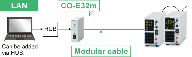
- Various optical interface adapters (additional products)
-
To use the optical interface, you need to prepare an optical interface adapter separately.
The following interface adapters are available according to your controller port.For details, refer to the CO/USB series.- CO-E32: LAN to optical interface adapter
- USB-OPT: USB to optical interface adapter
- CO-OPT2-9: RS-232C (9 pin) to optical interface adapter
- CO-OPT2-25: RS-232C (25 pin) to optical interface adapter
- CO-OPT4-25: RS-485 (25 pin) to optical interface adapter
- CO-G32: GPIB to optical interface adapter (Scheduled for discontinuation in December 2028)
Example of communication with optical fiber 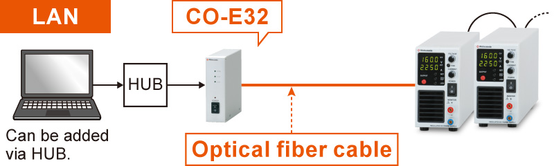
- AC INPUT CABLE
-
Standard
[360 W models]CABLE TYPE1 

125 V/10 A 2.5 meters
Fixed lengthStandard
[720 W models]CABLE TYPE8 125 V/125 A 2.5 meters
Fixed lengthStandard
[1080 W models]CABLE TYPE5 

300 V/25 A 2.5 meters Sold separately
[360 W and 720 W models]CABLE TYPE3 
250 V/10 A 2.5 meters
Fixed lengthSold separately
[360 W and 720 W models]CABLE TYPE4 
250 V/10 A 2.5 meters
Fixed lengthSold separately
[1080 W models]CABLE TYPE2 

125 V/15 A 2.5 meters
Fixed lengthPlease use the AC input cable suitable for the usage environment and the area. CABLE TYPE 3 and 4 correspond to CE marking.
- Application software
-
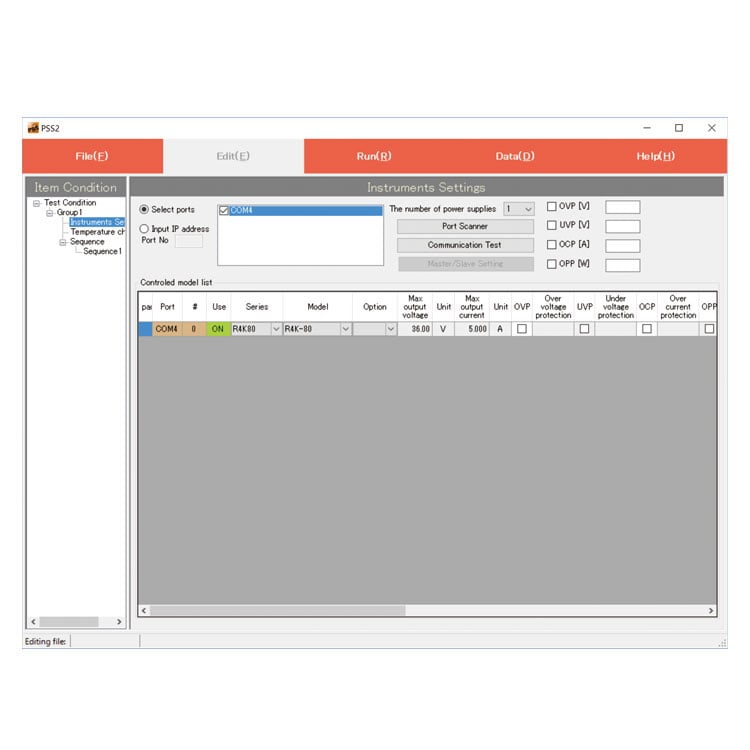
PSS2en series: Remote control, Test workflow design, and Data logging
Click here for the PSS2en seriesPSS2en is the dedicated software that can actuate various power supplies, electronic loads, and digital controllers for power supplies manufactured by Matsusada Precision Inc. with a simple setup.
It is perfect for the aging test, the burn-in test, and the withstand voltage test for electronic parts, as well as for the endurance test, intermittent/continuous operation test, or various simulation tests for automobile electric components.

Dimensions
Download
If you are unable to download a file
Please try the following solution.
- Please press Ctrl+F5 to clear the cache of your web browser and try again.
- Please restart your web browser and log in again to try again.
- Please change your web browser to another browser and try again.
- Restart the computer and try again.
- Please try again on a different computer.
-
TB series Datasheet
Date: 2026-01-15 rev 26
PDF (2,766 KB)
-
DC POWER SUPPLIES SELECTION GUIDE
Date: 2025-06-27 rev.02
PDF (5,265 KB)

-
How to Use DC Power Supplies
Date: 2025-11-11 rev 09
PDF (1,281 KB)

-
TB series Basic Instruction Manual (Both Japanese and English)
Date: 2021-04-13 rev 0.3
PDF (854 KB)
-
TB series Instruction Manual
Last updated: March 4, 2020 rev.0.6
PDF (3,050 KB)
-
TB series Instruction Manual (-LMi option)
Date: 2024-09-13 rev 0.2
PDF (1,482 KB)
-
USB driver (-LUs1 Option) for Windows 10, 11
Date: 2025-12-19 rev 2.12.36.20
ZIP(1,629KB)
-
USB driver (-LUs1 Option) for Windows XP, 7, 8, 8.1
Date: 2025-01-22 rev 1.7.6
ZIP (6,504 KB)
-
TB series IVI Driver (-LMi option)
Date: 2020-12-22 rev. 00
ZIP (8,379 KB)

-
TB series Outline Drawing (DXF, PDF)
Date: 2024-07-25
ZIP (2,387 KB)
Login Required
-
TB series Datasheet
Date: 2026-01-15 rev 26
PDF (2,766 KB)
-
DC POWER SUPPLIES SELECTION GUIDE
Date: 2025-06-27 rev.02
PDF (5,265 KB)
-
How to Use DC Power Supplies
Date: 2025-11-11 rev 09
PDF (1,281 KB)
-
TB series Basic Instruction Manual (Both Japanese and English)
Date: 2021-04-13 rev 0.3
PDF (854 KB)
-
TB series Instruction Manual
Last updated: March 4, 2020 rev.0.6
PDF (3,050 KB)
-
TB series Instruction Manual (-LMi option)
Date: 2024-09-13 rev 0.2
PDF (1,482 KB)
-
USB driver (-LUs1 Option) for Windows 10, 11
Date: 2025-12-19 rev 2.12.36.20
ZIP(1,629KB)
-
USB driver (-LUs1 Option) for Windows XP, 7, 8, 8.1
Date: 2025-01-22 rev 1.7.6
ZIP (6,504 KB)
-
TB series IVI Driver (-LMi option)
Date: 2020-12-22 rev. 00
ZIP (8,379 KB)
-
TB series Outline Drawing (DXF, PDF)
Date: 2024-07-25
ZIP (2,387 KB)
On this website, we provide only the latest versions of information and instruction manuals for our products. Therefore, the newest versions of manuals on the website may differ from those that came with products you purchased in the past.