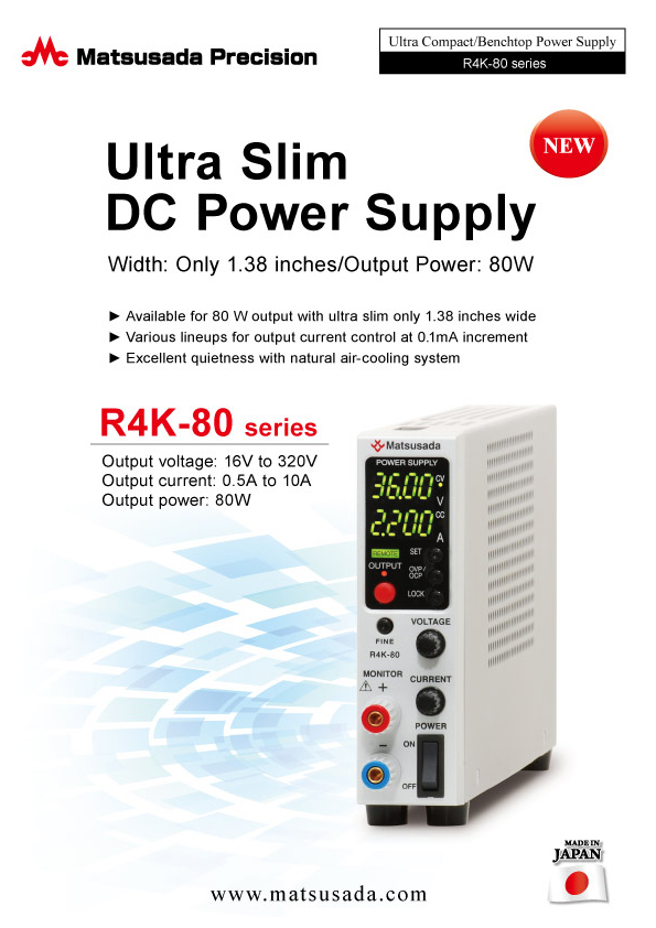
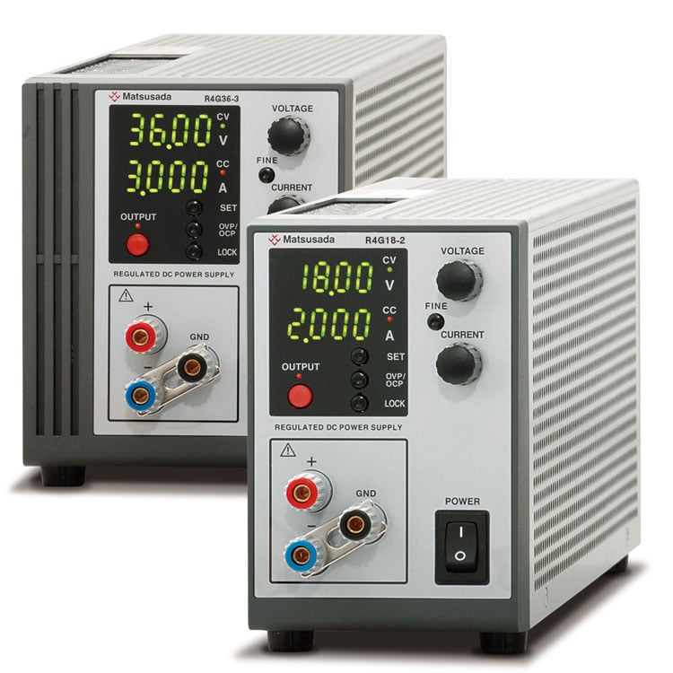
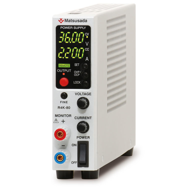
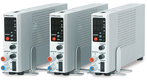
Ultra-Slim, High-Performance Benchtop Power Supply
The R4K-80 series is a programmable DC power supply designed for high precision and space efficiency. It features a newly added 4-digit digital meter and high-resolution D/A and A/D converters for precise setting and readback accuracy. Maintaining the compact form factor and ease of use of the conventional RK-80 series, the R4K-80 offers enhanced performance for demanding environments.
This series is an ideal choice for a wide range of applications, from laboratory research to automated production lines.
Features and Benefits
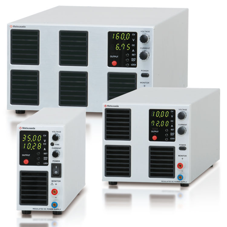
Compact and lightweight: Space-saving design optimized for benchtop use.
Silent operation: Fanless, naturally-cooled system ensures a quiet working environment.
Wide output range: Flexible voltage and current configurations within the 80 W power limit.
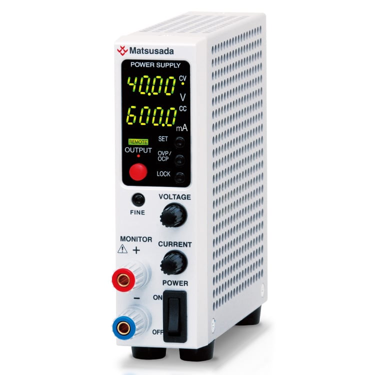
R4K-80L: 16 V / 10 A, R4K-80: 36 V / 5 A , R4K-80M: 110 V / 1.3 A, R4K-80H: 320 V / 0.5 A
Low noise: Proprietary power conversion technology optimized for research applications.
Universal input: Power factor correction (PFC) allows for global use.
Scalable: Supports master/slave operation and digital interface integration.
Useful New Five Additional Functions
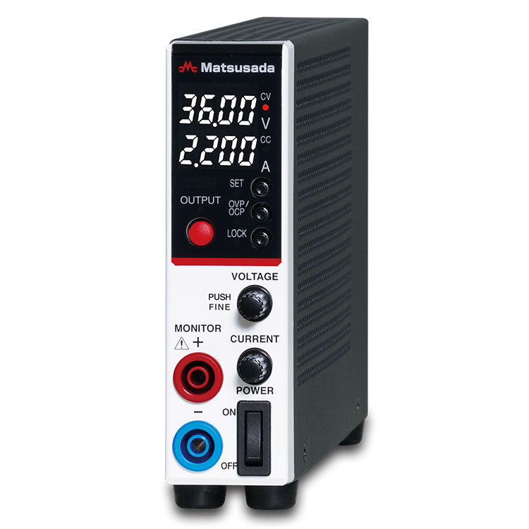
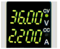
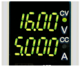
4-digit digital meter:
Precise display of output voltage and current.
High-resolution control:
Integrated D/A and A/D converters allow for fine adjustments via the rotary encoder.
Digital interface included:
Standard digital interface facilitates data logging and automated measurement.
Conversion adapters for RS-232C, RS-485, USB, or LAN (Ethernet) are sold separately.
Rapid setting:
The rotary encoder features a coarse/fine switching function, allowing for quick adjustments of voltage and current settings.
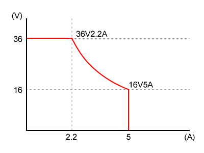
Flexible Operating Range
The R4K-80 series allows for flexible voltage and current settings within the rated 80 W power limit. This enables a single unit to cover a wide range of operating points.
Operation Note: Output voltage and current can be set arbitrarily as long as the total power does not exceed 80 W.
* This unit requires manual setting of voltage and current values; it does not automatically adjust the range during operation.
User-Friendly Design
New functions and a stylish front panel improve usability.
No.1Preset Display: Preset values are automatically displayed when the output is OFF.
No.2Enhanced Safety: Over Current Protection (OCP) is included for safer operation.
No.3Quick Lock: Features a one-touch lock function with two selectable modes.
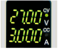
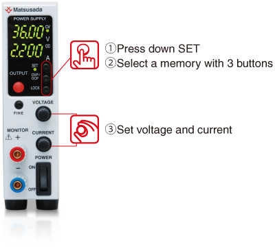
Memorize three voltage and current settings in addition to the standard preset values. There is no need to adjust the output when different settings, and convenient function for the production inspection process or testing which requires frequent data taking.
Memory (a)Memory (b)Memory (c)
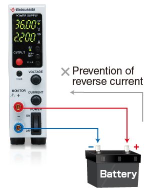
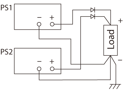
Sink Current Suppression
When supplying power to loads with capacities like batteries and capacitors, the sink current suppression is used to reduce the reverse current flowing from the load to the unit in order to prevent a voltage drop on the load as the output is OFF or the set voltage is lowered.
Note:
Reverse current cannot be controlled and stabilized. Connect a dummy resistor or reverse current prevention diode when the load of the reverse voltage is equal to or higher than the rated voltage (inductive loads, regenerative motors, etc.)
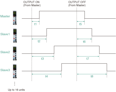
Delay Trigger Function
Only one R4K-80 is available when -LUs1, -LGob, or -LEt option is selected.
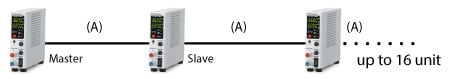
When turning OUTPUT ON/OFF, you can start or stop the output operation with some delay. The function is available not only for a single power supply but also for multiple units of Matsusada Precision DC power supplies in the digital interface *1 which are individually set values of output voltage/current in addition to a single power supply. *2
R4K-36 series, RK-80 series, RK series, and REK series For details, contact our sales office. They can be connected to up to 16 units.
Can be connected to up to 16 units.
Only for slave-local
In the case of the slave remote control, the exact same model of power supply needs to be used. Also, in the case of slave-local, each output voltage and current can be set individually. In the case of slave-remote, output voltage and current can be set with a one-control function in which each slave unit follows the master unit setting.
* +1 and +8 can be set respectively in 0.0 s to 99.9 s.
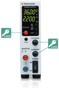
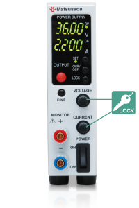
Two-level Lock Function
Two-level lock is selectable: "Full Lock" for locking all the switch operations and "Standard lock" for locking except for the output ON/OFF.
"Full lock" is used to prevent all erroneous operations, and "Standard lock" is for readily applying the emergency
stop along with misoperation prevention, which can ensure a "safe" operation.
(An emergency stop by the power switch is available in both types of lockings. )
Full LOCK
Locks all the switch operations except canceling the lock function.
It is especially suited to prevent misoperations in the remote control.
Standard LOCK
Locks the voltage/current setting switches.
It can prevent mistakenly changing the output setting in local control and immediately applying an emergency stop.
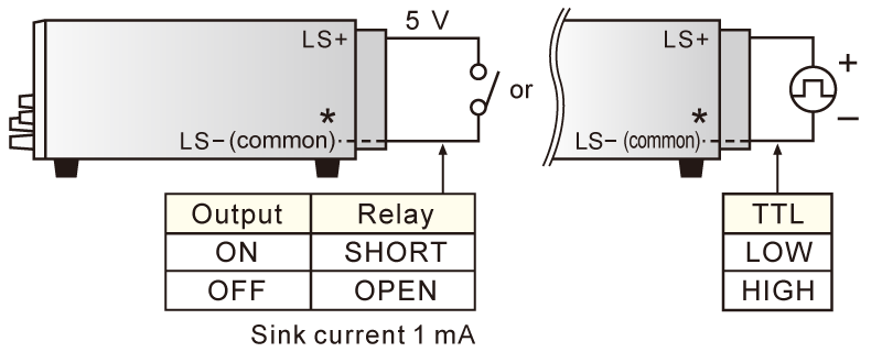
Remote Function
External output ON/OFF
Sink current 1 mA
* +S is common. So, the external control voltage shall be inputted with +S as a reference. Otherwise, it can cause failure.
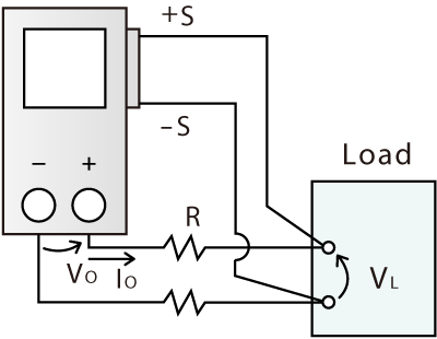
Remote sensing
The function ensures the prevention of stability deterioration, which could be caused by the voltage drop (V0-VL) due to the resistance (R) of the output wire or contact resistance.
Digital Interface Port (sold separately)
This is Matsusada Precision's proprietary digital communication port. This interface has modular type IN and OUT ports to allow daisy-chain connection. Combined with an adapter (sold separately). Multiple power supplies can be controlled at once. Adapters for LAN, USB, RS-232C, RS-485, and GPIB are available so that you can choose a suitable communication interface. One-control operation by master-slave connection is also possible.
Status output Fault/Output/OVP/OCP/OT/ACF/reversible sense connection/Interlock
Maximum 16 units digital control (-LGob option models: 32 units) digital control
One control function for multiple units
Write function
Output voltage setting/Output current setting
Percent mode (100.00%)
* voltage current value mode (maximum rated voltage and current value)
OVP setting/OCP setting
Percent mode (100.0%)
voltage current value mode (maximum overvoltage/overcurrent protection value)
Reading function
Output voltage reading/Output current reading
Percent mode (100.00%)
* voltage current value mode (maximum rated voltage and current value)
Output voltage setting/Output current setting
Percent mode (100.00%)
* voltage current value mode (maximum rated voltage and current value)
OVP setting/OCP setting
Percent mode (100.0%)
voltage current value mode (maximum overvoltage/overcurrent protection value)
* The Minimum value of each model is the same as the minimum display of the front panel meter.
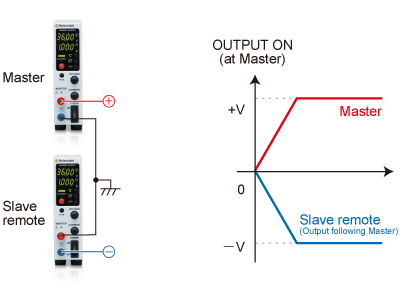
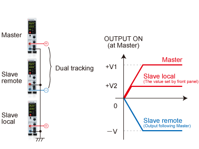
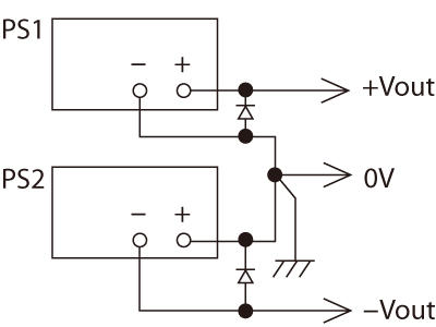
Dual Tracking, Multiple Outputs
Dual tracking control enables both positive and negative outputs simultaneously in master-slave control. In addition, using the slave local mode, the dual tracking operation can consist of multiple outputs. The positive and negative output voltages (+V and -V) in dual output will output in synchronization with turning on the power of the master machine.
* The function is unavailable for -LUs1 and -LEt options.
Dual trackingMultiple outputs
Example of Connection and Operation
Using the same multiple units of the R4K-80 series, the output voltage and output current can be increased by connecting the outputs in series or parallel.
Local control or digital master-slave control is recommended for control.
The external output ON/OFF terminal LS- is connected to the + output, so do not connect it to the commons of other power supplies.
Series operation
The total output voltage is up to 250 V. The output voltage exceeding 250 V is unavailable in a series connection. The output current will be the smallest value.
Parallel operation
Use the same value for voltage setting in parallel connection. The output current is the sum of each current. In order to prevent damage, set the OVP level of all the power supplies to the maximum.
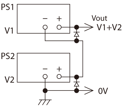
Split operation
+output and -output are available.
Two Features in -LDe Option
(1) Function for Pulse/Ramp and Master Follow
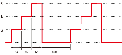
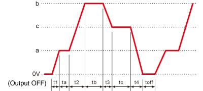
A. Pulse (Step) Sequence Function
The Sequence function lets you generate complex voltage and current patterns by automatically cycling through settings stored in memories a, b, and c. You can run the sequence continuously or for a specified number of cycles. By setting the duration of any step (a, b, c, or off) to 0.0, you can easily skip steps to create custom test patterns. This flexibility is ideal for product evaluation and reliability testing.
The parameters ta, tb, tc, and toff can be set to 0.0 s, or from 1.0 s to 99.9 h.
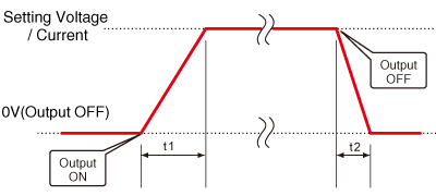
B. Ramp Function
The Ramp function provides linear control to gradually increase the output to a set voltage/current, or decrease it to zero. This feature is useful for applications that require a slow power-up or power-down.
* The ramp operation can be applied to: Voltage and Current, Voltage Only, or Current Only.
t1 and t2 can be set to 0 to 999 s, respectively
C. Combined Sequence and Ramp
For advanced control, the Sequence and Ramp functions can be used together. This allows you to create complex profiles by smoothly ramping the voltage and/or current between the discrete steps defined in memories a, b, and c. The entire waveform can be run continuously or for a pre-set number of cycles, making it a powerful tool for various testing scenarios.
t1 and t2 can be set from 0 s to 999 s, while ta, tb, tc, and toff can be set to 0.0 s or from 1.0 s to 99.9 h.
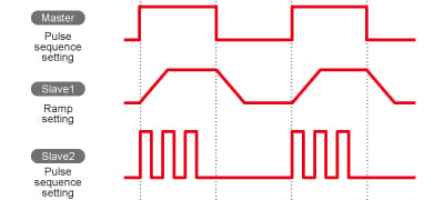
D. Master Follow
Pulse sequence actions at master-slave and output signal to slave units at ramp action are transmitted. By this function, it is possible to make slave units output on different output conditions from the master unit.
* The master follow function is only available with the standard interface.
Note; Accuracy of the timer at sequence action ±0.5%. Please take care usage at long-running.
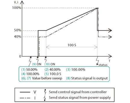
(2) Sweep Control Programming
Easy programming of sweep operation!
With the -LDe option, the available sweep commands are adapted by setting the arrival time and arrival conditions (voltage/current). Since there is no need to set commands that are repeated step by step, it is easier to create new programs and change conditions, saving a great deal of operation time. It also contributes to securing time for development, research, etc.
Example of usage that sweeps from constant value to undo it after attainment
Specifications
Input voltage
85 to 264 Vac, 50/60 Hz, Single-phase
Output voltage control
[Local] Rotary encoder on front panel
[Digital remote] Command
Output current control
[Local] Rotary encoder on front panel
[Digital remote] Command
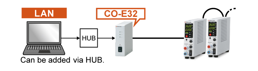
LAN Interface port
Enable digital control via LAN.
HUB shall be required between R4K-80 and the computer when controlling multiple R4K-80.
This option, the digital interface, is not attached. For more information on the digital interface, refer to the CO/USB series datasheet.
Master-slave function is unavailable.
-LGob *
Optical Interface port
This option replaces the standard digital interface with an optical interface port. Combined with a separately sold optical adapter, it provides electrical isolation between the power supply and the controller.
-LGob: Optical interface port + optical cable 2 meters
-LGob(Fc5): Optical interface port + optical cable 5 meters
-LGob(Fc10): Optical interface port + optical cable 10 meters
-LGob(Fc20): Optical interface port + optical cable 20 meters
-LGob(Fc40): Optical interface port + optical cable 40 meters
Recommended for the following environments:
Electrically noisy environments (e.g., near motors, coils, or inverters).
When the distance between the power supply and controller (PC/PLC) exceeds 2 meters.
Applications where improved safety and isolation are required.
-LH
High isolation voltage
With an isolation voltage of ±1kV, more R4K-80 series power supplies are available in series connection.
-LIc
Output current accumulation function
This option accumulates the output current and displays the value (up to 100 Ah). The accumulated value is stored even when the output is off. You can set the maximum accumulated output current in advance to stop the output. It is very suitable for applications such as controlling Electroplating solutions.
• Please consider the location of usage. High humidity environment can be the cause of failure and corrosion.
-LUs1 *
USB Interface port
Enable digital control via USB.
This option, the digital interface, is not attached. For more information on the digital interface, refer to the CO/USB series datasheet.
Master-Slave function is unavailable.
-L(Mc0.5), -L(Mc0.15) *
Changing of communications cable
The CO-M cable length can be selected from 0.15 meters or 0.5 meters. Select one of the two types above.
* Selecting each individual option simultaneously in -LEt, -LGob, -LUs1, and -L(Mc0.5) or -L(Mc0.15)
How to Order
When placing an order, please add the option code(s) after the model name. If adding two or more options, omit the “-L” from the second and subsequent option codes, and list them in alphabetical order, with the cable length option placed at the end. <Example> R4K-80-LDeGobHIc, R4K-80L-LDeHIcUs1
Accessories
Adapter for digital interface
To use the digital interface, you need to prepare a digital interface adapter separately. The following interface adapters are available according to the communication method of your controller port.
CO-E32m: LAN adapter
USB-MET/CO-U32m: USB adapter
CO-MET2-9: RS-232C (9 pin) adapter
CO-MET2-25: RS-232C (25 pin) adapter
CO-MET4-25: RS-485 (25 pin) adapter
CO-G32m: GPIB adapter (Scheduled for discontinuation in December 2028)
To use the optical interface, you need to prepare an optical interface adapter separately. The following interface adapters are available according to the communication method of your controller port.
CO-E32: LAN to optical interface adapter
USB-OPT: USB to optical interface adapter
CO-OPT2-9: RS-232C (9 pin) to optical interface adapter
CO-OPT2-25: RS-232C (25 pin) to optical interface adapter
CO-OPT4-25: RS-485 (25 pin) to optical interface adapter
CO-G32: GPIB to optical interface adapter (Scheduled for discontinuation in December 2028)
Select an appropriate AC input cable according to your operating environment and region. If you use the R4K-80 series in Europe, please be sure to contact our sales representatives.
Accessory Kit
Various accessories are available for convenient use of the unit.
Stand
The stand is useful to use as a single unit.
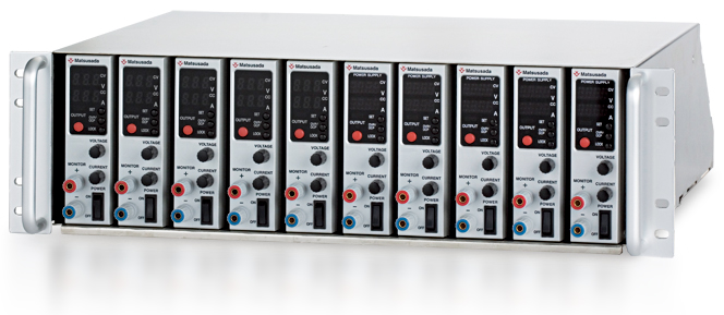
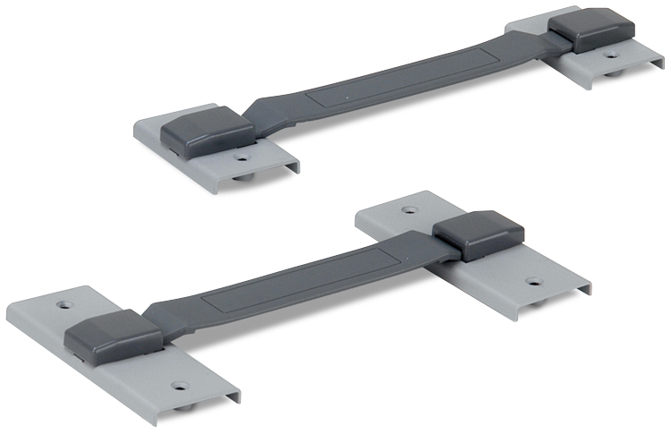
Binder
For the applications which require two to six units combination. Dual, triple, and quad-multiple operations are possible.
* A Cooling fan is needed for more than three units combination.
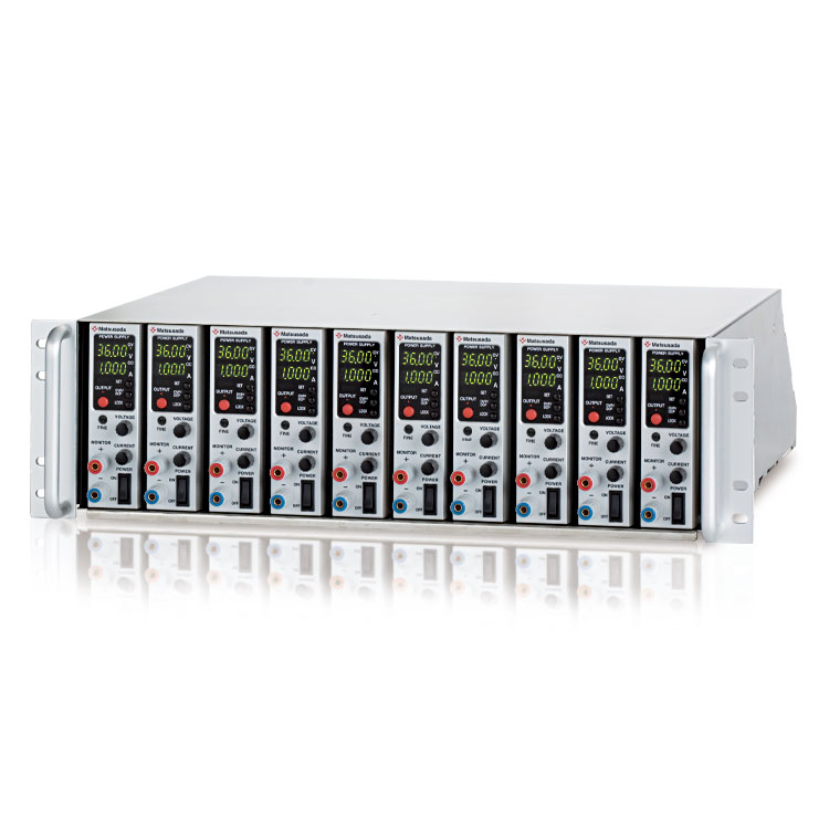
10 Units/1 rack shelf, and can be placed in a cabinet. Easy to take one unit out.
Best suitable for a system operation
With fan unit (100 Vac) * Contact our sales representatives.
The rack mount shelf enables consolidation to one.
* Power supply is not included in the accessories.
Application software
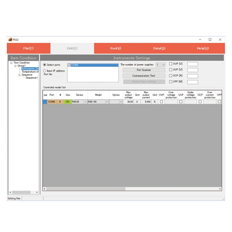
PSS2en series: Remote control, Test workflow design, and Data logging
PSS2en is the dedicated software that can actuate various power supplies, electronic loads, and digital controllers for power supplies manufactured by Matsusada Precision Inc. with a simple setup.
It is perfect for the aging test, the burn-in test, and the withstand voltage test for electronic parts, as well as for the endurance test, intermittent/continuous operation test, or various simulation tests for automobile electric components.
USB driver (-LUs1 Option) for Windows XP, 7, 8, 8.1
Date: 2025-01-22 rev 1.7.6 ZIP (6,504 KB)
R4K-80 series Outline Drawing (DXF, PDF)
Date: 2024-07-24 ZIP (283 KB)
On this website, we provide only the latest versions of information and instruction manuals for our products. Therefore, the newest versions of manuals on the website may differ from those that came with products you purchased in the past.


 Binder
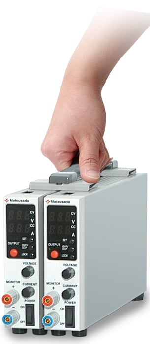
 Rack mount shelf (RMO series)