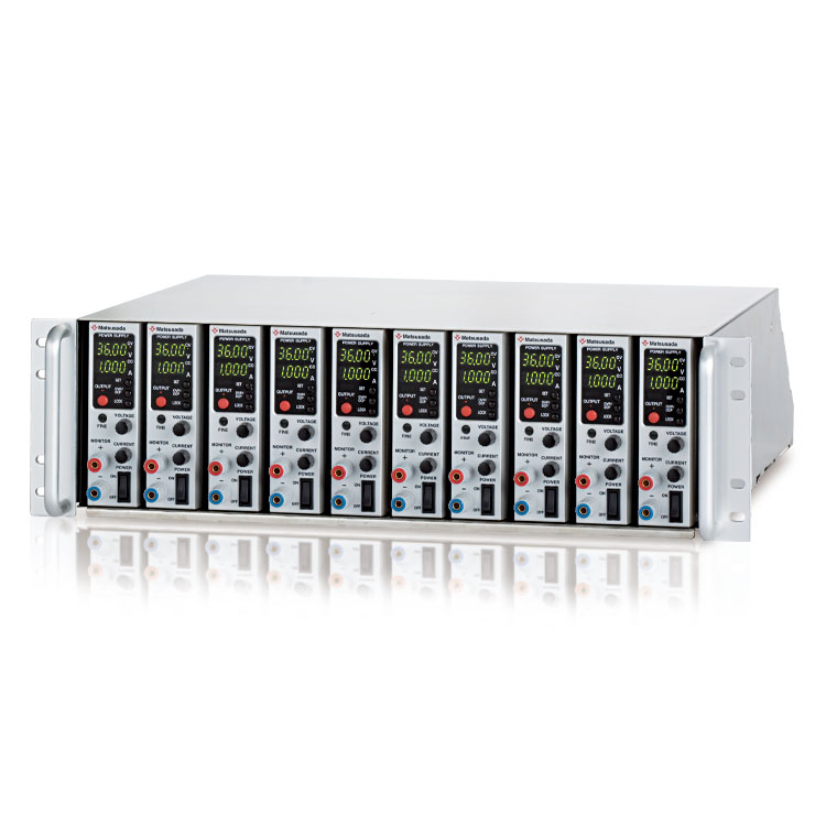
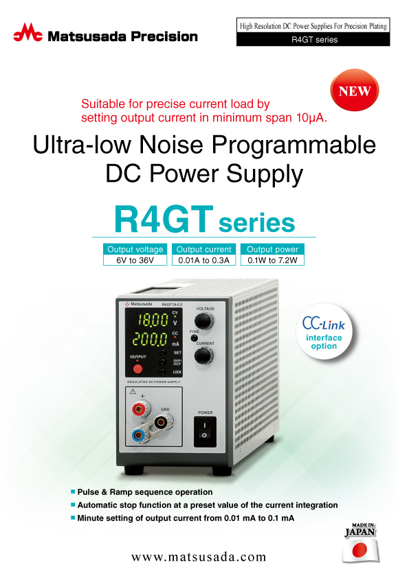
Ultra-low Noise Programmable DC Power Supply
Ideal for microcurrent loads requiring high-resolution current settings
- Voltage range: 6V to 36V
- Current: 0.01A to 0.3A
- Power: 0.1W to 7.2W
- CC-Link interface option
Precise Setting of Current and Output with High Resolution D/A and A/D Converter
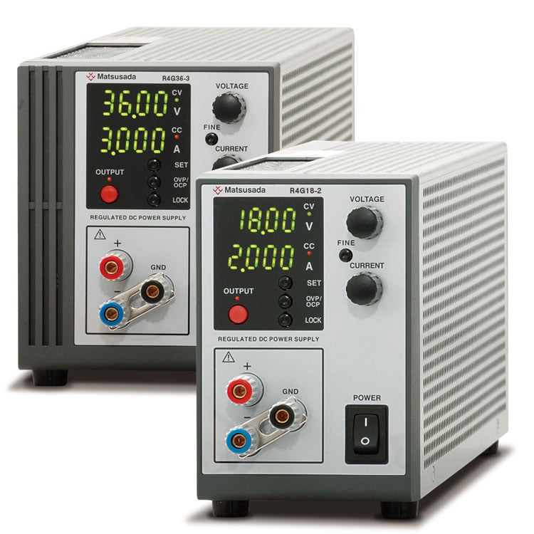
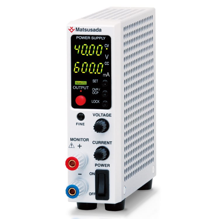
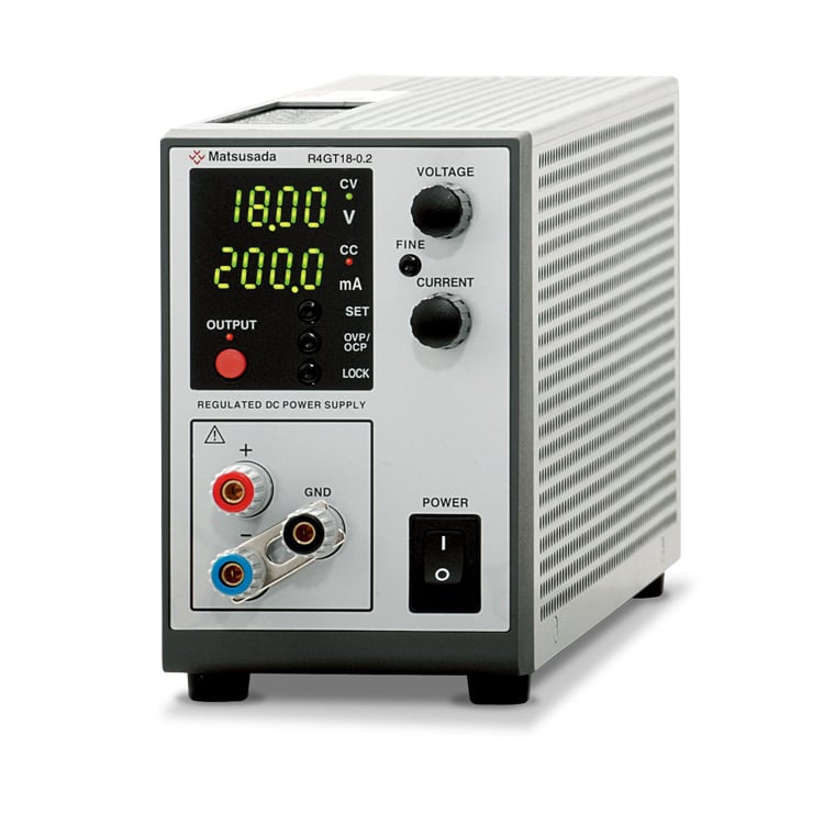
The R4GT series is an ultra-low noise, high-resolution programmable DC power supply engineered for demanding applications such as precision plating. Building on the proven platform of our renowned R4G series, the R4GT offers exceptionally precise current control with a resolution down to 10 μA. Its superior stability and performance also make it the ideal choice for testing current-sensitive components, including LEDs and a wide variety of electronic sensors.
Superior usability is achieved with the FINE function, which allows for quick voltage and current setting.
Moreover, offer digital communication options, making them suitable for a wide range of applications, from experiments to automated production lines.
FEATURES AND BENEFITS
- Function for Pulse and Ramp Action (option)
Sequential operation is provided by using pulse combined with ramp action without external programming devices or computers. - Four-Digit Output Voltage and Current Meters
The unit features 4-digit voltage and current meters. Selectable setting resolutions (1 mV/10 mV or 0.01 mA/0.1 mA, depending on the model) allow for precise output control without the need for an external multimeter. - Current Integration and Auto-Stop Function (Optional)
This function integrates the total output current over time and can automatically stop the output at a preset value. This is invaluable for precise control of plating thickness and managing plating solutions. - High-Speed Response
High-speed response with ultra-low ripple and noise is applied to enhance electroplating performance with high precision - Standard Analog and Optional Digital Interfaces
Analog remote control comes standard. For integration into automated systems, a wide array of optional digital interfaces are available, including CC-Link, USB, LAN, GPIB, and RS-232C/485. - Fanless Design for Quiet Operation
The unit utilizes natural convection cooling for silent operation. Additionally, the fully enclosed heat sink design ensures enhanced safety. - Suitable for precise current load by setting output current in minimum span 10μA.
- Automatic stop function at a preset value of the current integration
APPLICATIONS
- Electroplating
- Evaluation of plating solution
- Hull cell testing
- Various sensors
- Electrochemical experiments
- Electronic devices
- Tests for luminous elements, LED, Organic Electroluminescence (OEL), etc. to handle minute current
Models
- Do not operate the unit in environments containing corrosive gases or high humidity.
- All the models in the below table are positive common power supply. Please contact our sales office for negative common models.
| Model | Output | ||
|---|---|---|---|
| Voltage | Current | Power | |
| R4GT6-0.3 | 0 to 6 V | 0 to 0.3 A | 1.8 W |
| R4GT10-0.01 | 0 to 10 V | 0 to 0.01 A | 0.1 W |
| R4GT18-0.1 | 0 to 18 V | 0 to 0.1 A | 1.8 W |
| R4GT18-0.2 | 0 to 18 V | 0 to 0.2 A | 3.6 W |
| R4GT36-0.1 | 0 to 36 V | 0 to 0.1 A | 3.6 W |
| R4GT36-0.2 | 0 to 36 V | 0 to 0.2 A | 7.2 W |
* Values are ones at local control. It is possible to set finer (or higher-resolution) values by digital communication. Refer to page 4 “Digital Control Function”.
- Discontinued models
The following model is no longer available as we have stopped production and sales.
Functions
Pulse/Ramp (Option)
Following output controls of A to E are applicable.
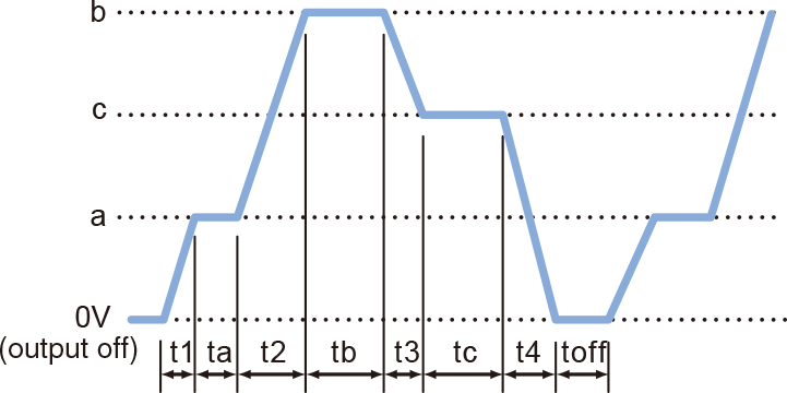
A. Pulse (Step) Sequence Function
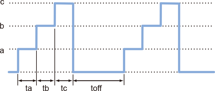
The Sequence function lets you generate complex voltage and current patterns by automatically cycling through settings stored in memories a, b, c, through t. You can run the sequence continuously or for a specified number of cycles. By setting the duration of any step (a, b, c, through t or off) to 0.0, you can easily skip steps to create custom test patterns. This flexibility is ideal for product evaluation and reliability testing.
B. Ramp Function
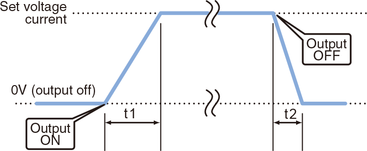
The Ramp function provides linear control to gradually increase the output to a set voltage/current, or decrease it to zero. This feature is useful for applications that require a slow power-up or power-down. *The ramp operation can be applied to: Voltage and Current, Voltage Only, or Current Only.
C. Combined Sequence and Ramp
For advanced control, the Sequence and Ramp functions can be used together. This allows you to create complex profiles by smoothly ramping the voltage and/or current between the discrete steps defined in memories a, b, c, through t. The unit can run the entire waveform continuously or for a pre-defined number of cycles, and allows you to set up to 20 voltage and current values, making it a powerful tool for a variety of test scenarios.
D. Delayed trigger ramp
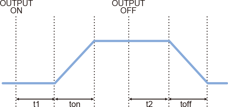
* ton can be set in 0.1 s to 9999 h 59 m 59.9 s and toff can be set in 0.0 to 9999 h 59 m 59.9 s
This function combines the delayed trigger and ramp features. The ramp output starts after a preset delay once the output is turned on.
E. Master Follow
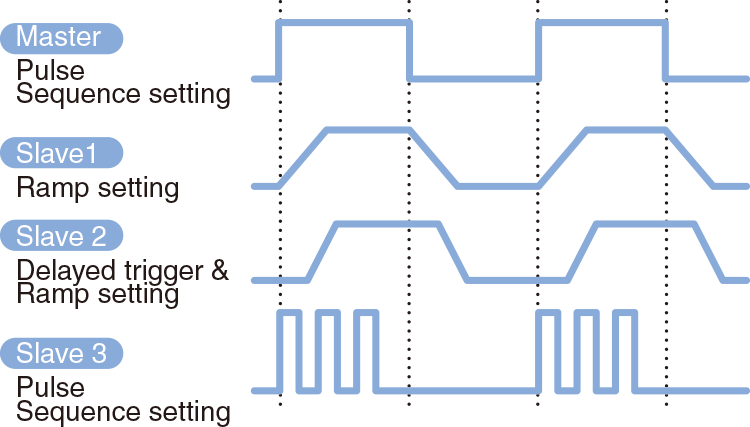
The Master-Follow function allows slave units to track the output status of the master unit in a master/slave configuration. The master unit transmits its output status to the slave units, enabling interlocked operation. Different operation modes can be set for master and slave units to support complex testing requirements.
External Analog Remote Control
- External Output ON/OFF
- Output can be turned ON/OFF by relay or TTL signal.
Logic of OUTPUT can be made reverse.
- Output Control (Voltage, Current)
- Use control voltage as floating but not grounding.
Potential on COMMON is the same as one of the positive output terminal. If COMMON in the customer's equipment is grounded, not only power supply can not be controlled, but also damage to equipment may be caused. And if a multi-channel and non-isolated Programmable Logic Controller (PLC) is utilized, please take care that the ground of other equipment is connected through the PLC in a certain case.
- Output Monitor (Voltage, Current)
- Output of Status
- COMMON is floating with the output of the open collector for each COMMON.
Voltage resistance 30 Vdc, Sink current ≤ 5 mA
- Remote Sensing
- Prevent degrade stability due to voltage drop (Vo-VL) by resistance (R) in output wiring or contact resistance. (up to max. 0.5 V)
Parallel Operation by One Control
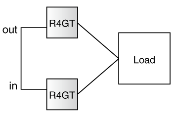
One master unit can control several slave units that are parallel connected. It is possible to increase output current by connecting two units of the same model power supply in parallel.
Digital Control Function (at selected various optional digital interfaces)
| Control Function |
|
|
|---|---|---|
| Write Function | Setting Output Voltage | Percent Mode *1, Voltage or Current Value Mode, *2 |
| Setting Output Current | ||
| Setting OVP | Percent Mode *1, Voltage or Current Value Mode, *2 | |
| Setting OCP | ||
| Read Function | Measured Output Voltage | Percent Mode *1, Voltage or Current Value Mode, *2 |
| Measured Output Current | ||
| Setting Output Voltage | Percent Mode *1, Voltage or Current Value Mode, *2 | |
| Setting Output Current | ||
| Setting OVP | Percent Mode *1, Voltage or Current Value Mode, *2 | |
| Setting OCP | ||
- Minimum setting unit for each model is one ten-thousandth (100.00%).
- Minimum setting unit for each model is one count of the indicator.
Specifications
- Input voltage
- 120 Vac ±10%, 50/60 Hz, Single-phase
- Output voltage control
-
[Local] Rotary encoder on front panel
[Analog remote] External control voltage 0 to 10 Vdc
[Digital remote] Command (option) - Output current control
-
[Local] Rotary encoder on front panel
[Analog remote] External control voltage 0 to 10 Vdc
[Digital remote] Command (option)
Options
- -LCk *1 NEW
-
CC-Link Interface Port
A CC-link master unit such as a PLC can control power supplies with a CC-link compatible with CC-link ver1.10, which is possible to operate as a CC-link device station. One unit occupies two stations, and a maximum of 32 units can be controllable. Please refer to the CC-link association web for CC-link details.
Multiple units can be simultaneously controllable by direct, Hub, or daisy chain connection.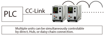
- -LDe
-
Pulse/Ramp Sequence
For details ”Functions”.
- -LGmb *1 *2
-
Digital Interface Port
This is Matsusada Precision's proprietary digital communication port. This interface has modular type IN and OUT ports to allow daisy-chain connection. Combined with an adapter (sold separately). Multiple power supplies can be controlled at once. Adapters for LAN, USB, RS-232C, RS-485, and GPIB are available so that you can choose a suitable communication interface. One-control operation by master/slave connection is also possible.- -LGmb: Digital Interface port + CO-M cable 2 meters
- -LGmb (Mc0.15): Digital Interface port + CO-M cable 0.15 meters
- -LGmb (Mc0.5): Digital Interface port + CO-M cable 0.5 meters
Master/Slave 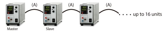
If a noisy environment is expected, the -LGob optical interface port option is required.
- LGob *1 *2
-
Optical Interface Port
This option changes the standard interfaces to a built-in optical interface port. By combining this option with an adapter for optical connection (sold separately), communication between the control device and the power supply can be controlled in an isolated state. Be sure to select this option when using the product in the following environments.- -LGob: Optical interface port + optical cable 2 meters
- -LGob(Fc5): Optical interface port + optical cable 5 meters
- -LGob(Fc10): Optical interface port + optical cable 10 meters
- -LGob(Fc20): Optical interface port + optical cable 20 meters
- -LGob(Fc40): Optical interface port + optical cable 40 meters
Select the optional optical interface board (-LGob) when using this DC power supply under the following conditions.
- Noisy environments such as factories (example: when motors or coils are used near loads or power sources).
- If this power supply and your controller (PC or PLC) cannot be installed within 2 meters.
- When there is a possibility of arcing or output short-circuit.
To use the optical interface, you need to prepare an optical interface adapter separately.
For details, click here.
- -LH
-
High Isolation Voltage
With isolation voltage by ±500 Vdc, more R4GT series power supplies are available in series connection.
Note: The total output voltage is up to 500 V. The output current will be the smallest value.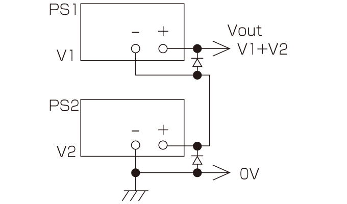
- -LIc
-
Output Current Integration Function
This option provides a current integration function that displays the total charge delivered in Ampere-hours (up to 100 Ah). The integrated value is retained even when the output is off. This feature is extremely useful for managing the chemistry of plating solutions and ensuring repeatable results, as the output can be automatically shut off once a preset total charge has been supplied.
- -LMi *1
-
Multi Digital Interface
This interface comes with LAN, USB*, and RS-485 (Multi-drop) interfaces, providing flexible connectivity for various communication environments. (Simultaneous use of interfaces is not supported.) Furthermore, an SCPI-compliant IVI driver is available for download from our website.
This driver simplifies the development of control programs using a wide variety of languages such as LabVIEW, MATLAB, Python, C#, and Visual Basic.
*The USB port conforms to the USB Test and Measurement Class (USBTMC) protocol. If your application requires compatibility with the USB Communications Device Class (USB CDC), the RS-485 port can be used as a virtual COM port by using a third-party USB to RS-485 adapter.
- -LUs1 *1 *2
-
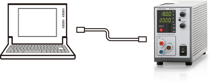
USB Interface Port
Digital Control via USB is enabled.One unit can be connected to each USB port on the computer. If the computer has insufficient ports, a USB hub may be used. Note that proper operation is not guaranteed with all USB hubs.
- -LZ
-
Handle for Carrying
It is available for all the models (getting higher by 8 mm).
- -L(200V), -L(220V), -L(240V)
-
Supports input voltages other than 120 Vac.
Note: Accuracy of the timer during sequence operation ±0.1%. Please take care of usage at long-running operations.
- Either one of these options is selectable
- For the detailed function of an optical interface, USB interface, RS-232C interface, and digital interface, please refer to the datasheet of digital controller CO/USB series.
How to Order
When placing an order, please add the option code(s) after the model name. If adding two or more options, omit the “-L” from the second and subsequent option codes, and list them in alphabetical order, with the input voltage option placed at the end.
Example: R4GT18-0.2-LDeGob(Fc10)(200V)
Accessories
- Adapters for various digital interfaces
-
To use Matsusada Precision's digital interface, you need to prepare a digital interface adapter separately.
The following interface adapters are available according to your controller port.- CO-E32m: LAN Adapter
- USB-MET/CO-U32m: USB Adapter
- CO-MET2-9: RS-232C (9 pin) Adapter
- CO-MET2-25: RS-232C (25 pin) Adapter
-
CO-MET4-25: RS-485 (25 pin) Adapter
CO-MET2-9/CO-MET2-25/CO-MET4-25: The connector is D-sub type. - CO-G32m: GPIB Adapter (Scheduled for discontinuation in December 2028)
Example of communication with a digital adapter 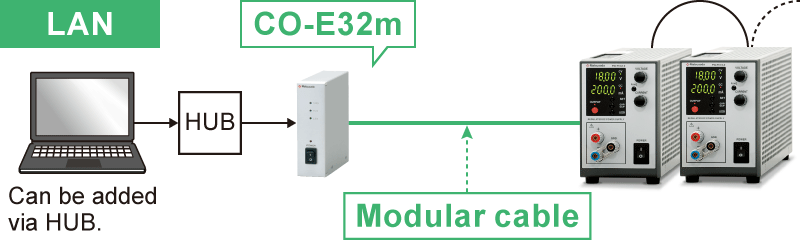
- Optical isolation adapter
-
To use the optical interface, you need to prepare an optical interface adapter separately.
The following interface adapters are available according to your controller port.- CO-E32: LAN Adapter
- USB-OPT: USB Adapter
- CO-OPT2-9: RS-232C (9 pin) Adapter
- CO-OPT2-25: RS-232C (25 pin) Adapter
- CO-OPT4-25: RS-485 (25 pin) Adapter
- CO-G32: GPIB Adapter
Example of communication with optical fiber 
- AC Input Cable
-
The R4GT series comes with one AC power cord.
Standard CABLE TYPE1 

125 V/10 A 2.5 meters Fixed length
-L(200V), -L(220V),
-L(240V) optionsCABLE TYPE3 
250 V/10 A 2.5 meters Fixed length
Sold separately CABLE TYPE4 
250 V/10 A 2.5 meters Fixed length
- Application software
-
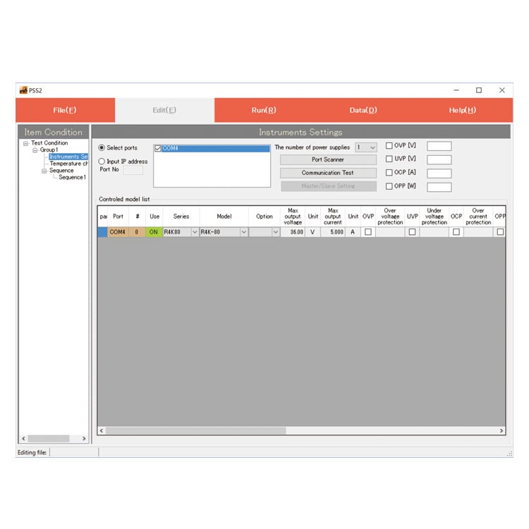
PSS2en series: Remote control, Test workflow design, and Data logging
PSS2en is the dedicated software that can actuate various power supplies, electronic loads, and digital controllers for power supplies manufactured by Matsusada Precision Inc. with a simple setup.
It is perfect for the aging test, the burn-in test and the withstand voltage test for electronic parts, and for the endurance test, intermittent/continuous operation test, or various simulation tests for electric components of automobiles.
For details, refer to PSS2en page.
Dimensions
Download
If you are unable to download a file
Please try the following solution.
- Please press Ctrl+F5 to clear the cache of your web browser and try again.
- Please restart your web browser and log in again to try again.
- Please change your web browser to another browser and try again.
- Restart the computer and try again.
- Please try again on a different computer.
-
R4GT series Datasheet
Date: 2026-01-26 rev 21
PDF (1,849 KB)
-
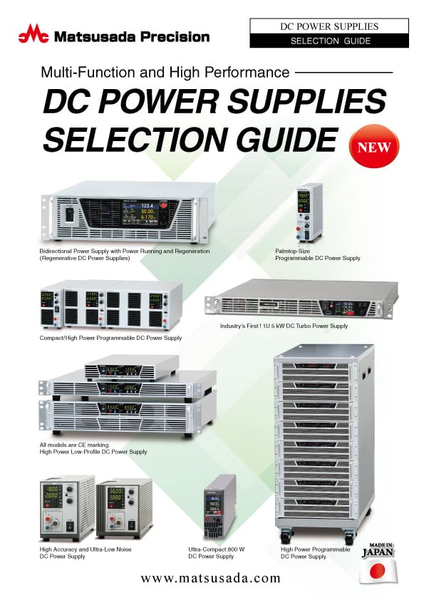
DC POWER SUPPLIES SELECTION GUIDE
Date: 2025-06-27 rev.02
PDF (5,265 KB)

-
How to Use DC Power Supplies
Date: 2025-11-11 rev 09
PDF (1,281 KB)

-
R4GT series Basic Instruction Manual
Date: 2020-09-17 rev 0.0
PDF (367 KB)
-
R4GT series Instruction Manual
Date: 2022-3-14 rev.0.12
PDF (1,283 KB)
-
R4G/R4GT/R4GN series Instruction Manual (LMi Option)
Date: 2021-09-02 rev. 0.5
PDF (1,140 KB)
-
R4G/R4GT series Instruction Manual (LGmb, LGob, LUs1 and LRs in Option)
Date: 2023-08-07 rev.0.5
PDF (1,340KB)
-
R4G/R4GT series Instruction Manual (LCk option)
Date: 2023-3-14 rev.0.6
PDF (1,013 KB)
-
R4GT series Instruction Manual (LDe and LIc in Option)
Date: 2020-11-17 rev 0.1
PDF (575 KB)
-
R4GT series Rise and Fall Times
Date: 2020-10-29 rev. 01
PDF (205 KB)
-
USB driver (-LUs1 Option) for Windows 10, 11
Date: 2025-12-19 rev 2.12.36.20
ZIP(1,629KB)
-
USB driver (-LUs1 Option) for Windows XP, 7, 8, 8.1
Date: 2025-01-22 rev 1.7.6
ZIP (6,504 KB)
-
R4G/R4GT series LMi Option Driver (IVI Driver)
Last updated: February 10, 2020 rev.0.1
Zip File (8,754 KB)

-
R4GT series Outline Drawing (DXF, PDF)
Date: 2024-07-24
ZIP (1,037 KB)
Login Required
-
R4GT series Datasheet
Date: 2026-01-26 rev 21
PDF (1,849 KB)
-
DC POWER SUPPLIES SELECTION GUIDE
Date: 2025-06-27 rev.02
PDF (5,265 KB)
-
How to Use DC Power Supplies
Date: 2025-11-11 rev 09
PDF (1,281 KB)
-
R4GT series Basic Instruction Manual
Date: 2020-09-17 rev 0.0
PDF (367 KB)
-
R4GT series Instruction Manual
Date: 2022-3-14 rev.0.12
PDF (1,283 KB)
-
R4G/R4GT/R4GN series Instruction Manual (LMi Option)
Date: 2021-09-02 rev. 0.5
PDF (1,140 KB)
-
R4G/R4GT series Instruction Manual (LGmb, LGob, LUs1 and LRs in Option)
Date: 2023-08-07 rev.0.5
PDF (1,340KB)
-
R4G/R4GT series Instruction Manual (LCk option)
Date: 2023-3-14 rev.0.6
PDF (1,013 KB)
-
R4GT series Instruction Manual (LDe and LIc in Option)
Date: 2020-11-17 rev 0.1
PDF (575 KB)
-
R4GT series Rise and Fall Times
Date: 2020-10-29 rev. 01
PDF (205 KB)
-
USB driver (-LUs1 Option) for Windows 10, 11
Date: 2025-12-19 rev 2.12.36.20
ZIP(1,629KB)
-
USB driver (-LUs1 Option) for Windows XP, 7, 8, 8.1
Date: 2025-01-22 rev 1.7.6
ZIP (6,504 KB)
-
R4G/R4GT series LMi Option Driver (IVI Driver)
Last updated: February 10, 2020 rev.0.1
Zip File (8,754 KB)
-
R4GT series Outline Drawing (DXF, PDF)
Date: 2024-07-24
ZIP (1,037 KB)
On this website, we provide only the latest versions of information and instruction manuals for our products. Therefore, the newest versions of manuals on the website may differ from those that came with products you purchased in the past.