
Satellite Power Systems (PCDU): Architecture and Development / Validation Solutions
Once launched, satellites operate in an extremely harsh environment where on-orbit repair is virtually impossible. One of the most critical subsystems for ensuring mission success is the Electrical Power Subsystem (EPS), which generates, regulates, and distributes electrical power throughout the spacecraft. In modern satellites, the PCDU (Power Conditioning and Distribution Unit), which integrates power regulation and power distribution functions, is widely adopted. While the EPS refers to the spacecraft's overall power subsystem, the PCDU serves as its core functional unit.
This article explains the internal architecture of the PCDU, typical bus-voltage configurations based on satellite class, and advanced validation methods using Matsusada Precision power supplies and electronic load systems.
1. The PCDU: The Core of a Satellite Power System
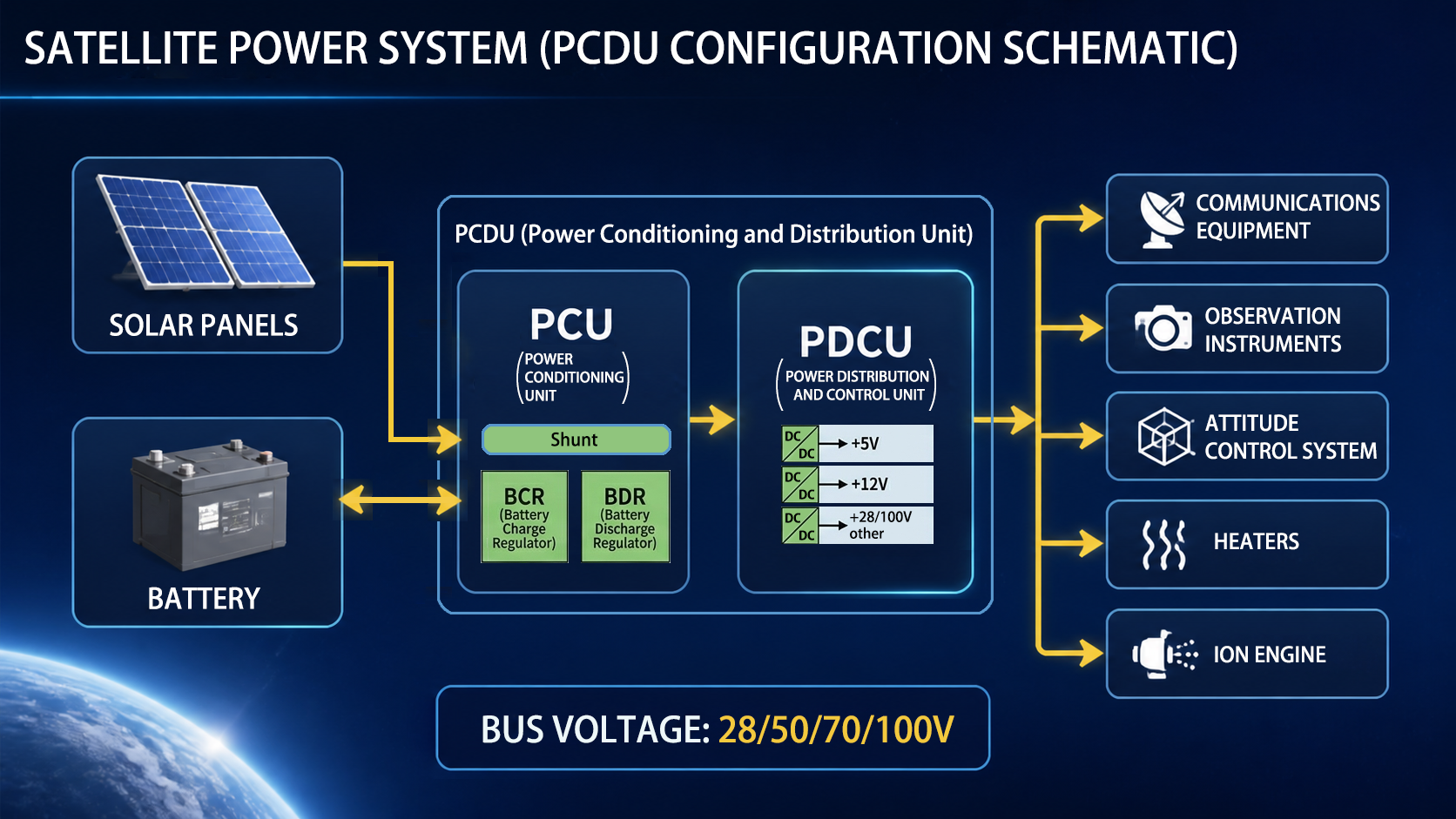
Power management in space fundamentally depends on how efficiently energy generated from sunlight can be controlled and utilized. The PCDU is generally composed of two primary functional blocks: the Power Control Unit (PCU) and the Power Distribution Control Unit (PDCU).
1-1. Power Control Unit (PCU)
The PCU optimizes the balance between power generation and energy storage while stabilizing the spacecraft's DC bus voltage, which serves as the electrical lifeline of the entire satellite.
-
Precision Control of Shunt Circuits
Solar Array Paddles (SAPs) generate output power that varies significantly depending on solar incidence angle and temperature. When generated power exceeds spacecraft consumption and the battery is fully charged, unmanaged excess energy may cause a rapid rise in bus voltage, potentially resulting in severe damage to the entire system.
Shunt circuits stabilize the bus voltage by dissipating excess power as heat and radiating that heat into space through thermal radiators.
-
BCR (Battery Charge Regulator)
The BCR converts power generated by the solar array into the optimal charging current and voltage according to the battery State of Charge (SoC). Since overcharging can lead to battery degradation or thermal runaway, extremely precise control is required.
-
BDR (Battery Discharge Regulator)
During eclipse periods, when the satellite passes into Earth's shadow, or during high-power events such as ion engine operation, the BDR supplies power from the battery system. Even when battery voltage fluctuates, high-efficiency power conversion and regulation functions including buck, boost, or buck-boost conversion are required to maintain a stable DC bus voltage to the spacecraft loads.
1-2. Power Distribution Control Unit (PDCU)
The PDCU distributes stabilized main bus power from the PCU to onboard subsystems while simultaneously providing protection functions.
-
Voltage Conversion Using Multiple DC-DC Converters
Main bus voltages (for example, 28V) cannot be supplied directly to all onboard electronics. Internal DC-DC converters generate the voltages required by individual subsystems, including:
- 5V / 3.3V: Onboard computers (OBCs) and data-processing units
- 12V / 15V: Communication equipment (transponders) and various sensors
- 28V / 50V / 100V-class: Large actuators, heaters, and mission payload equipment
-
Switching and Protection Functions (LCL: Latching Current Limiter)
To prevent failures such as short circuits or abnormal current conditions from propagating to the main power bus and causing a spacecraft-wide shutdown (dead bus condition), high-speed protection circuits are incorporated into the PDCU.
Many LCLs also include reset/retry functionality to prevent total spacecraft shutdown caused by a single fault.
-
HCE (Heater Control Electronics)
Spacecraft are exposed to extreme temperature variations ranging from cryogenic cold to intense heat. To maintain sensitive electronics and batteries within their allowable operating temperature ranges, the PDCU precisely controls spacecraft heaters.
2. Satellite Classes, Bus Voltages, and Power Levels
As satellite mission scale increases, both required power capacity and bus voltage levels generally increase.
| Satellite Category | Typical Mass | Bus Voltage | Power Capacity (at EOL*) | Technical Characteristics |
|---|---|---|---|---|
| Ultra-Small Satellite (CubeSat) | 1 kg - 10 kg | 3.3V/5V/12V | 10W - 50W | Technology-demonstration platforms developed by universities and startups. Often utilize commercial lithium-ion batteries for low-cost and rapid development. |
| Small Satellite | 100 kg - 500 kg | 28V | 500W - 2kW | Used for Earth observation and space environment monitoring. 28V is the most widely adopted standard bus voltage in aerospace and avionics systems. |
| Medium/Large Satellite | 1 t - 5 t+ | 50V/70V/100V-class | 5kW - 20kW | Geostationary communication and broadcasting satellites. Higher bus voltages reduce wiring losses and heat generation during high-power transmission. Designed for thousands of charge/discharge cycles. |
In satellites equipped with gridded ion engines for electric propulsion, acceleration electrodes may require high voltages in the kilovolt range. In such systems, dedicated high-voltage Power Processing Units (PPUs) are installed. For more information about ion engines, please see our technical blog: "What is an Ion Engine? Mechanism, Structure, and Applications."
- Why is the bus voltage of artificial satellites 28V?
- The 28 V bus voltage used in many artificial satellites originates from aerospace and military aircraft systems, where 24 V batteries operated at about 28 V during charging. This standard was inherited because many reliable aerospace components were already designed for 28 V operation. Technically, 28 V provides a good balance between efficiency and safety. Higher voltage reduces current for the same power, which decreases cable weight, power loss, and heat generation--important factors in spacecraft design. At the same time, excessively high voltage increases the risk of arcing and insulation breakdown in vacuum and plasma environments. Early spacecraft battery technologies such as NiCd and NiH2 also naturally matched this voltage range. Although modern high-power satellites sometimes use 50-100 V systems, 28 V remains a proven and reliable standard for many spacecraft applications.
- How do satellites overcome limited battery cycle life?
- Satellites overcome the limited cycle life of batteries mainly by operating them under very conservative conditions. Instead of deep charge and discharge cycles, spacecraft typically use only 10-30% depth of discharge, greatly extending battery life to tens of thousands of cycles. Solar arrays provide most of the spacecraft's power during sunlight periods, while batteries are mainly used during eclipses and temporary peak loads. Satellites also use specialized battery technologies such as NiCd, NiH2, and space-qualified lithium-ion cells, which are designed for high reliability and long operational life. In addition, strict thermal management, precise charging control, cell balancing, and redundant battery architectures help minimize degradation. These techniques allow spacecraft batteries to operate reliably for 10-20 years despite frequent orbital charge/discharge cycling.
3. Importance of Ground Validation Using Matsusada Precision Power Supplies and Electronic Loads
During satellite development, pre-launch electrical interface testing is one of the most time-consuming and critical phases. The following sections explain how Matsusada Precision products are utilized in spacecraft power-system validation.
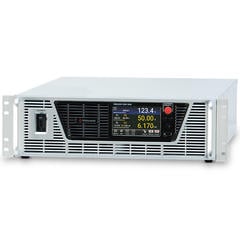
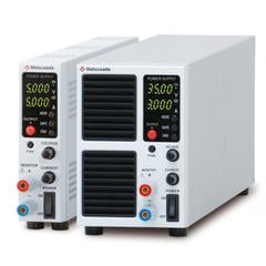
3-1. Solar Array Simulation (SAS) Using Fast-Response Power Supplies
Operating actual solar array paddles on the ground requires large-scale solar simulators and is often impractical. Instead, specialized power supplies capable of reproducing the nonlinear I-V characteristics of solar arrays are used.
-
Validation Objectives
Rapid transitions between sunlight and eclipse conditions, as well as reduced power-generation scenarios caused by partial solar-array deployment failures, can be simulated to verify whether the PCDU and power-control systems correctly perform MPPT (Maximum Power Point Tracking) or shunt regulation control.
-
Advantages of Matsusada Products
High-speed voltage and current response characteristics enable real-time reproduction of complex solar-array I-V curves, allowing highly accurate evaluation.
3-2. Battery Simulation Using Bidirectional Power Supplies
Actual space-qualified batteries are extremely expensive and have limited charge/discharge cycle life. In addition, accidental overcharging during testing may create fire hazards.
-
Validation Objectives
Battery simulators are used to evaluate BCR charging characteristics and BDR discharge stability under varying battery voltage conditions. Bidirectional power supplies can emulate both power sourcing and power sinking operation within a single unit.
-
Advantages of Matsusada Products
By utilizing regenerative bidirectional power supplies, heat generation and air-conditioning load during charge/discharge testing can be significantly reduced, enabling safer and more energy-efficient test environments.
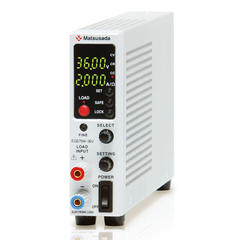
3-3. PDCU Distribution Testing Using Electronic Loads
When power is distributed from the PDCU to onboard subsystems, it is essential to verify that load fluctuations on one line do not adversely affect other systems.
-
Validation Objectives
Multiple electronic loads are used to simulate inrush currents during communication equipment startup and intermittent heater operation. These tests rigorously evaluate bus-voltage transient response and verify whether protection circuits such as LCLs operate according to design specifications.
-
Advantages of Matsusada Products
Multi-channel electronic loads allow simultaneous and independently programmable control of dozens of spacecraft power lines.
3-4. Ion Engine Evaluation Using High-Precision High-Voltage Power Supplies
Testing electric propulsion systems requires highly stable high-voltage power in the kilovolt range.
-
Validation Objectives
- Discharge characteristic testing in vacuum chambers
- Long-duration power delivery tests to ion-engine grid electrodes
-
Advantages of Matsusada Products
Ultra-low ripple and highly stable output characteristics minimize power-supply-induced noise during ion-engine development, where extremely small thrust fluctuations must be measured accurately.
4. The Future of Space Development: Evolution of Power Technology
Future space development is advancing beyond traditional missions toward deep-space exploration, including lunar and Mars missions, while also entering an era of large-scale Low Earth Orbit (LEO) satellite constellations and highly connected satellite networks. In parallel, a wide range of satellite platforms--including Synthetic Aperture Radar (SAR) satellites for Earth observation, Geostationary Earth Orbit (GEO) satellites for communications and broadcasting, and Global Navigation Satellite System (GNSS) satellites for positioning and navigation services--are becoming increasingly important components of global infrastructure.
These next-generation space systems require not only further reductions in size and weight, higher power density, and improved energy efficiency, but also the high reliability necessary for long-term operation in the harsh space environment.
Leveraging decades of expertise in high-voltage power supply technology and precision regulation technology, Matsusada Precision continues to support the development of future space infrastructure through a broad lineup of DC power supplies, bidirectional power supplies, and electronic load systems.
We provide high-precision testing environments that enable satellite and spacecraft design engineers to perform comprehensive ground validation and approach launch day with confidence.
- Related Terms:
-
- Avionics
- Battery
- Battery Simulator
- DC/DC Converter
- EPS
- PCDU
- PCU
- PDCU
- Bus Voltage
- HCE
- DC Power
- Shunt Circuit
- BCR
- BDR
- LCL
- Solar Array Paddle (SAP)
- Solar Array Simulator (SAS)
- MPPT (Maximum Power Point Tracking)
- Ion Engine
- Ground Validation
- LEO Satellite Constellations
- Satellite Networks
- SAR Satellites
- GEO Satellites
- GNSS Satellites