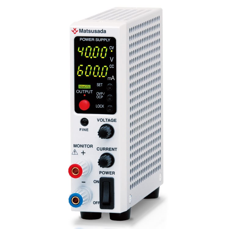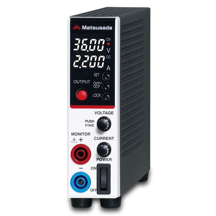
ULTRA SLIM DC POWER SUPPLY
Width: Only 1.38 inches (35mm)/Output Power: 80W
- 16V to 320V
0.5A to 10A
80W -

Width of only 1.38 inches
Weight of 2.2 lb -

Low-noise switching regulator -

Supports a wide range of outputs
Advanced Performance in an Ultra-Slim Design
The P4KF-80 series is a next-generation programmable DC power supply featuring an ultra-slim 35 mm profile. Engineered for high reliability, it combines low ripple noise with fast rise time-performance characteristics often difficult to achieve simultaneously in compact units. The fanless design ensures quiet operation, making it ideal for R&D environments and desktop applications. Standard features include LAN/USB interfaces and safety terminals, supporting precise measurements for circuit board testing and system integration.
Key Features
- Ultra-Compact Design: Width of only 35 mm (1.38 in) and weight of 1 kg (2.2 lb) for space-saving integration.
- Silent Operation: Fanless natural convection cooling effectively eliminates acoustic noise.
- Flexible Output: Supports a wide range of voltage and current settings within the 80 W power envelope.
- Low Noise: Optimized switching regulator design suitable for precision R&D applications.
- Global Input: Universal AC input with power factor correction for use anywhere.
- Versatile Connectivity: Supports Dual Tracking, Multi-linkage, and Master/Slave configurations.
- Clear Interface: Highly visible 4-digit display for accurate monitoring.
- High Precision: Equipped with high-resolution D/A and A/D converters.
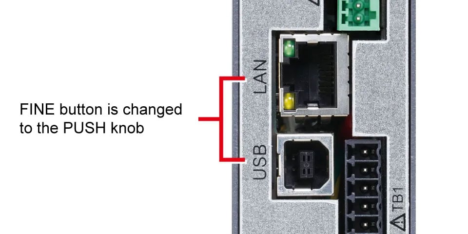
- Standard Digital Interfaces: Built-in LAN and USB ports for easy data collection and automated measurement.
- Standalone Testing: Flexible pulse and ramp functions allow test pattern generation without an external PC.
- Intuitive Control: Rotary encoder with a push-button ensures quick and precise voltage/current adjustments.
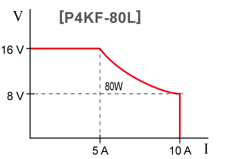
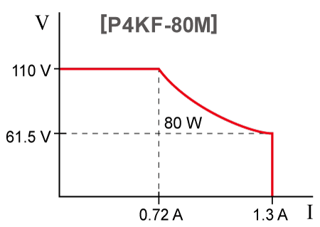
Flexible Power Range for Wider Applications
Flexible voltage and current settings with 80 W variable range and output ON
*This is not an auto-ranging feature that consistently delivers 80 W; settings may need to be readjusted.
Output range image


Enhanced Usability and Safety
Building on the performance of the R4K-80 series, the P4KF-80 offers improved circuit design, operational ease, and safety features.
Key Improvements
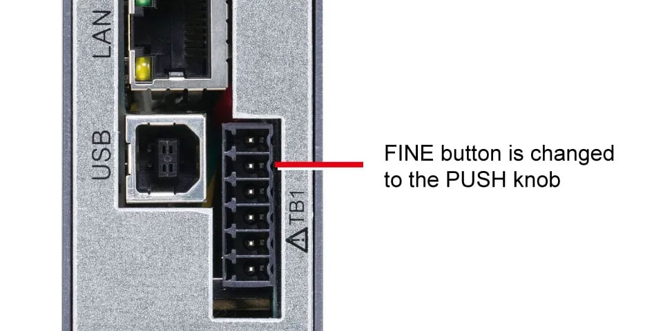
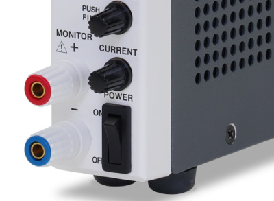
Push-and-Turn Encoder Knob
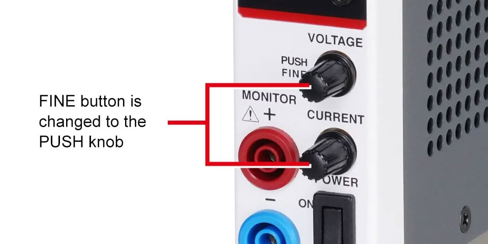
Replaces the "FINE" button for quicker coarse and fine adjustments.
Safety Output Terminals
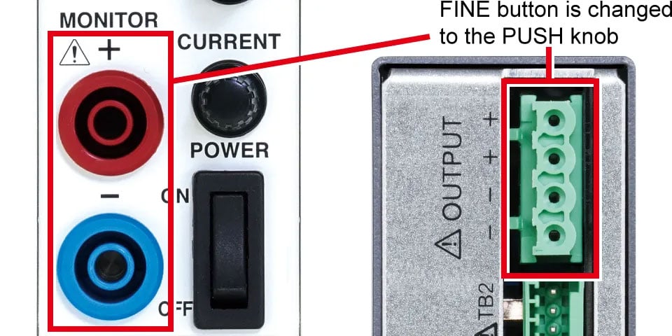
Designed for use with banana plugs to prevent accidental contact.
Standard LAN and USB Ports
Standard Analog Remote Control
Performance Comparison
The P4KF-80 series has a new circuit configuration that simultaneously improves ripple and noise and rise-time performance, which were previously trade-offs.
The compact power supply synonymous with Matsusada Precision has undergone further evolution!
Ripple and noise
![Ripple and noise [Existing R4K-80] | P4KF-80 series | DC power supply Benchtop | Matsusada Precision](/product/images/pro_img/p4kf-80/p4kf-80_ripple-before-960w.png)
![Ripple and noise [NEW P4KF-80] | P4KF-80 series | DC power supply Benchtop | Matsusada Precision](/product/images/pro_img/p4kf-80/p4kf-80_ripple-after-960w.png)
Rise time
![Rise time [Existing R4K-80] | P4KF-80 series | DC power supply Benchtop | Matsusada Precision](/product/images/pro_img/p4kf-80/p4kf-80_up-before-960w.png)
![Rise time [NEW P4KF-80] | P4KF-80 series | DC power supply Benchtop | Matsusada Precision](/product/images/pro_img/p4kf-80/p4kf-80_up-after-960w.png)
Models
| Model | Output voltage [V] | Output current [A] | Output power [W] | Ripple * | |
|---|---|---|---|---|---|
| [mVrms] | [mArms] | ||||
| P4KF-80L | 0 to 16 V | 0 to 10 A | 80 W | 4m V | 6m A |
| P4KF-80N | 0 to 36 V | 0 to 5 A | 5m V | 4m A | |
| P4KF-80M | 0 to 110 V | 0 to 1.3 A | 6m V | 2m A | |
| P4KF-80H | 0 to 320 V | 0 to 0.5 A | 10 mV | 1 mA | |
| P4KF-80X Coming soon | 0 to 400 V | 0 to 0.4 A | 12 mV | 0.1 mA | |
Functions
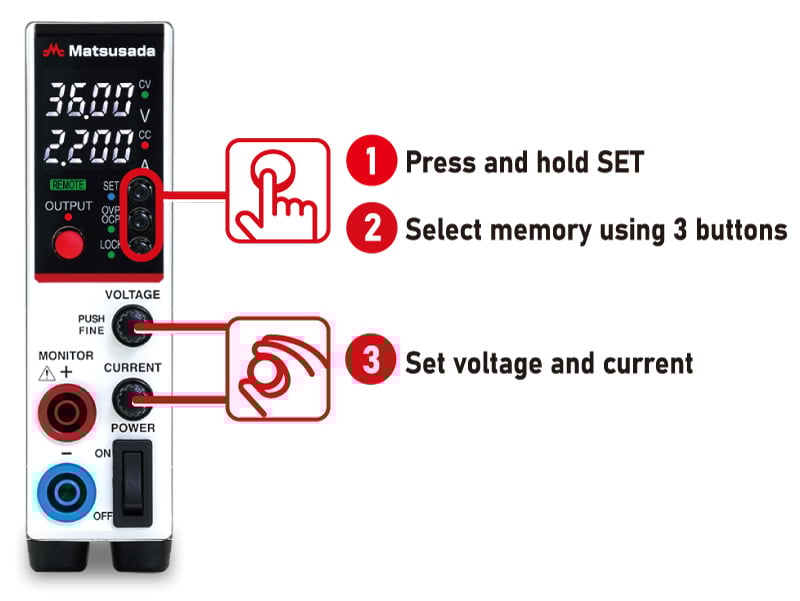
Multi-Set Memories
Store and recall up to three voltage and current presets in addition to standard settings. This function eliminates the need for repetitive manual adjustments, significantly improving efficiency for recurring test patterns or production line inspections.


Backflow Current Prevention
An integrated diode prevents reverse current from flowing from the load back into the power supply. This protection is essential when testing batteries, capacitors, or other capacitive loads that may retain a charge.
Note: This feature prevents backflow but does not stabilize or control reverse current. For inductive loads (e.g., regenerative motors) where reverse voltage may exceed the rated voltage, an external dummy resistor or reverse current protection diode is required.
2-Mode Lock
Two modes can be set: "Full LOCK" to lock all front panel operations, and "Normal LOCK" allows operation of the Output ON/OFF button while locking other settings. Set to "Full LOCK" mode if you want to prevent accidental operation without fail, or set to "Normal LOCK" mode if you want to prevent accidental operation but stop output locally.
* Emergency stop is possible in either mode with the power switch.
Analog Remote Control (The following master-slave control does not support this analog remote control.)
Voltage and Current Control
Output voltage and current can be set by an external control voltage (Vcon: 0 to 10 Vdc, Icon: 0 to 10 Vdc) or a potentiometer.
* -S is common. External control voltage must be referenced to -S to prevent malfunction.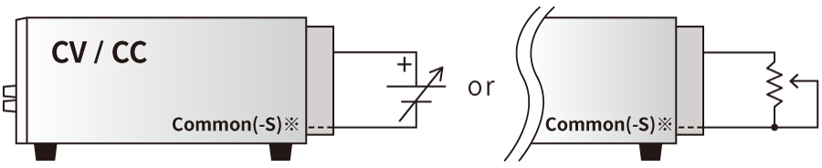
| Vout/Iout | Vcon/Icon | Resistor |
|---|---|---|
| 0 to MAX | 0 to approx. 10Vdc | 0 to approx. 10kΩ |
*Common is almost at the same potential as -S. External control voltage should be input with reference to -S. Grounding common may cause failure or malfunction.
Remote output ON/OFF control
Output ON/OFF can be controlled by relay and TTL.
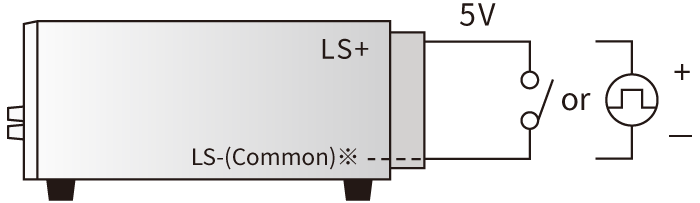
| Output | Relay | TTL |
|---|---|---|
| ON | Short | LOW |
| OFF | Open | HIGH |
Sink current 1mA
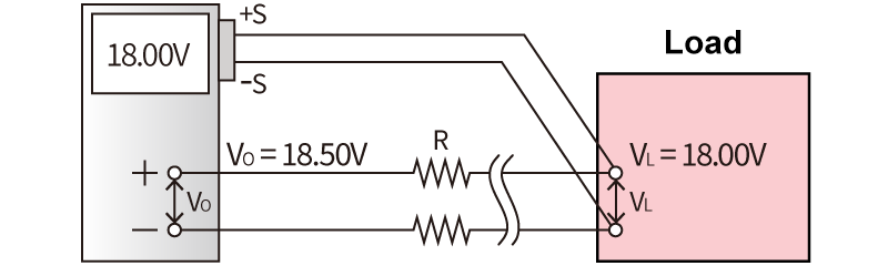
*LS- is almost at the same potential as common and -S. Input the control voltage with respect to -S. Grounding common may cause failure or malfunction.Remote sensing
Compensates for voltage drop (Vo-VL) due to output line resistance up to 3.7V*.
Master-Slave Control (Requires -LGmb or -LGob option)
Enables synchronized control where a designated master unit manages the output settings of connected slave units. This simplifies operation for higher power requirements.
* Individual slave settings are possible in "Slave Local Mode."* When connected in parallel to a single load, current sharing may not be perfectly equal.
* The -LGob (optical) option is recommended for electrically noisy environments.
Please contact us for master-slave configurations involving different models.

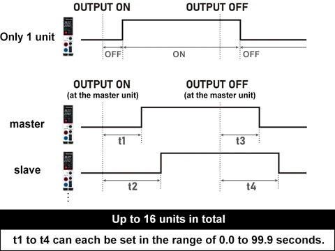
Delay Trigger (Requires -LGmb or -LGob option; multiple units can be configured)
The delay trigger function can delay start/stop output from the OUTPUT ON/OFF timing. The function is available not only for a single power supply but also for multiple units of Matsusada DC power supplies in the digital interface*1 which are individually set values of output voltage/current in addition to a single power supply.*2
- R4K-36 series, R4K-80 series, RK-80 series, RK series, TB series, RKT series, REKJ/REK series, and PVCEJ/PVCE series. For details, contact our sales office. They can be connected up to 16 units.
- Only for slave-local In case of slave remote control, exact same model of power supply need to be used. Also, in case of slave-local, each output voltage and current can be set individually. In case of slave-remote, output voltage and current can be set with one-control function which each slave unit follows the master unit setting.
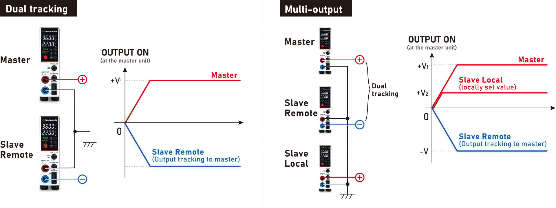
Dual Tracking and Multiple Outputs (available only when -LGmb or -LGob option is selected)
Dual tracking control is possible by connecting the power supplies as positive and negative outputs at the time of master-slave operation to control both positive and negative outputs at the same time.
In addition, the slave local mode, in which each power supply is set individually, and dual tracking operation can be combined to create a multi-output configuration.
Digital Control
- Control command
-
- ON/OFF setting of Output
- Various status displays (output status, operating status, OVP, OCP, OTP, ACF, sense reverse connection, external output ON/OFF)
- Batch control of up to 16 units (available only when -LGmb or -LGob option is selected)
- Write command
-
Output voltage setting/output current setting
* Voltage/Current value mode (maximum rated voltage/current value)OVP setting/OCP setting
Voltage/Current value mode OVP setting/OCP setting (maximum overvoltage/Overcurrent protection value)
- Read command
-
Output voltage measurement/output current measurement
* Voltage/Current value mode (maximum rated voltage/current value)Output voltage setpoint/output current setpoint
* Voltage/Current value mode (maximum rated voltage/current value)OVP setting/OCP setting
Voltage/Current value mode (maximum overvoltage/Overcurrent protection value)
Pulse and Ramp Sequence/Master Follow Function (only with additional -LDe option)
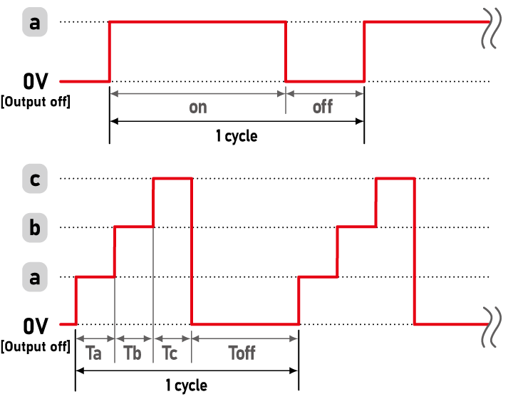
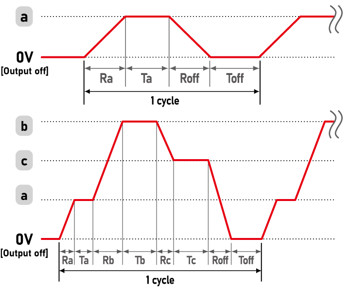
Enhanced Pulse/Ramp Sequence Function
The P4KF-80 series features a significantly upgraded sequence function. Unlike previous models, the time duration for each step (a, b, and c) can be set individually, allowing for more complex and precise test patterns without an external PC.
The power supply alone can control the following output patterns/sequences (A to D).
- Controllable Time
-
[Maximum Setting Time] 9999h (59m59.9s)
[Minimum Setting Increment] 0.1s
A. Pulse Sequence
This function allows you to set up a sequence with the voltage and current values set by the memory function of the power supply. It can be used without a PC or other control device.
Sequence operation combined with a multi-set function is also possible.
| Controllable Time and Count |
Minimum Setting Time Output on: 1.0s Others: 0.0s (0.1–0.9s is invalid) Maximum Number of Operations 9999 |
|---|
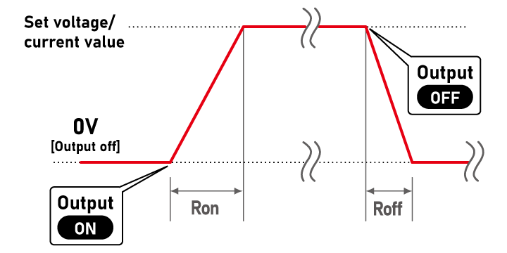
B. Ramp
This function allows the user to set the rise time and fall time to a set voltage/current value. Voltage only, current only, or both voltage and current values can be set.
| Controllable Time |
Minimum Setting Time 0.0s |
|---|
C. Pulse Sequence with Ramp
This function can be used in combination with the pulse sequence function. Sequence operation combined with a multi-set function is also possible.
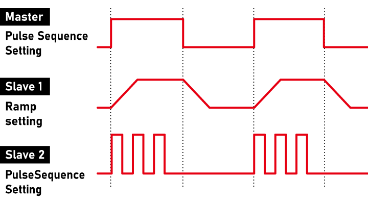
D. Master Follow
(This operation requires a master-slave connection with the -Lde option and the -LGmb or -LGob option.)
This function allows the master and slave units to output different voltage and current values by sending output signals to the slave unit during pulse sequence operation and ramp-rate control at the time of master-slave operation.
Note: The accuracy of timer operation for sequence is ±0.5%. Please use caution when using the product in long-term running operations.
Specifications
- Input voltage
- 85 to 264 Vac, 50/60 Hz, Single-phase
- Output voltage control
-
[Local] Rotary encoder on front panel
[Analog remote] External control voltage 0 to 10 Vdc or external 10kΩ potentiometer
[Digital remote] Command - Output current control
-
[Local] Rotary encoder on front panel
[Analog remote] External control voltage 0 to 10 Vdc or external 10kΩ potentiometer
[Digital remote] Command
Options
- -LBp
-
Binding Post New Arrival
Changes the front monitor terminal to a protruding binding post. Binding posts are useful when connecting not only banana plugs but also bare wires directly, ring terminals, spade terminals, and alligator clips.
- -LDe
-
Pulse and Ramp Sequence/Master Follow
See page Pulse and ramp sequence/master follow function for details.
- -LGmb *1 *2
-
Digital Interface Port
This option changes the standard USB and LAN interfaces to the proprietary digital interface port.
By combining this option with an adapter for digital connection (additional accessories), multiple units can be centrally controlled via LAN/USB/RS-232C/RS-485/GPIB. This option also enables the master-slave one-control feature, allowing a single master unit to manage multiple slave units.- -LGmb: Digital interface port and communication cable 2 meters
- -LGmb(Mc0.15): Digital interface port and communication cable 0.15 meters
- -LGmb(Mc0.5): Digital interface port and communication cable 0.5 meters
- -LGob *1 *2
-
Optical Interface Port
This option changes the standard interfaces to a built-in optical interface port. By combining this option with an adapter for optical connection (additional accessories), communication between the control device and the power supply can be controlled in an isolated state. Be sure to select this option when using the product in the following environments.- Noisy environments such as in factories (e.g., when motors or coils are used near loads or power sources)
- If this power supply and your controller (PC or PLC) cannot be installed within 2 meters
- When there is a possibility of arcing or output short-circuit
- -LGob: Optical interface port and optical cable 2 meters
- -LGob(Fc5): Optical interface port and Optical cable 5 meters
- -LGob(Fc10): Optical interface port and optical cable 10 meters
- -LGob(Fc20): Optical interface port and optical cable 20 meters
- -LGob(Fc40): Optical interface port and optical cable 40 meters
- -LIc *3
-
Current Integration
The output current is totalized and the value is displayed (up to 100 Ah). The totalized value is retained even when the output is turned off. In addition, the maximum integrated current value at which the output is stopped can be set in advance, which is useful for applications such as plating solution control.
Note: Please pay close attention to the installation location, as a humid environment may cause corrosion or malfunction.
- -LNp
-
Without Safety Plug (included accessory)
- These options cannot be selected at the same time.
- Standard LAN and USB ports are not provided when these options are selected. For more information on the functions of the digital interface adapters, please referto the datasheet for the CO/USB series of power supply digital controllers.
Ordering information
When placing an order, please add the option code(s) after the model name. If adding two or more options, omit the “-L” from the second and subsequent option codes, and list them in alphabetical order.
Example: P4KF-80N-LDeGobIc
Accessories
- Adapters for various digital interfaces (additional products)
-
To use Matsusada Precision's digital interface, you need to prepare a digital interface adapter separately.
The following interface adapters are available according to your controller port.For details, refer to CO/USB series.- CO-E32m: LAN adapter
- CO-U32m USB adapter
- CO-MET2-9 RS-232C (9 pin) adapter
- CO-MET2-25: RS-232C (25 pin) adapter
- CO-MET4-25 RS-485 (25 pin) adapter
- CO-G32m GPIB adapter (Scheduled for discontinuation in December 2028)
Adapter for digital interface 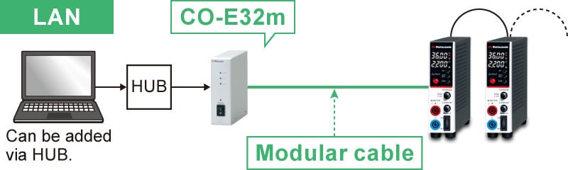
- Various optical interface adapters (additional products)
-
To use the optical interface, you need to prepare an optical interface adapter separately.
The following interface adapters are available according to your controller port.For details, refer to CO/USB series.- CO-E32: LAN to optical interface adapter
- USB-OPT: USB to optical interface adapter
- CO-OPT2-9: RS-232C (9 pin) to optical interface adapter
- CO-OPT2-25: RS-232C (25 pin) to optical interface adapter
- CO-OPT4-25: RS-485 (25 pin) to optical interface adapter
- CO-G32: GPIB to optical interface adapter (Scheduled for discontinuation in December 2028)
Example of communication with optical fiber 
- AC Input Cable
| Included accessory | CABLE TYPE1 |  |
 |
125 V/10 A |
|---|---|---|---|---|
| Additional accessory | CABLE TYPE3 | |
 |
250 V/10 A |
| Additional accessory | CABLE TYPE4 | |
 |
250 V/10 A |
| Additional accessory | CABLE TYPE13 | |
 |
250 V/15 A |
- Additional Products
-
• Stand
Prevents the power supply unit from tipping over.
• Double plug
This plug can connect Y-type crimp terminals.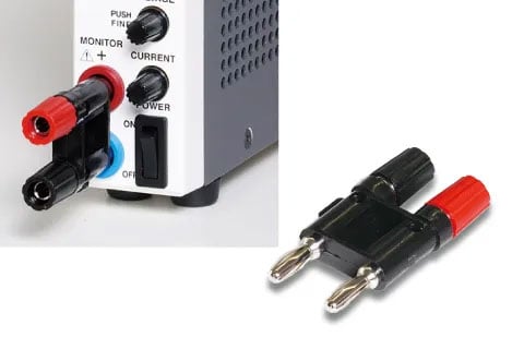
-
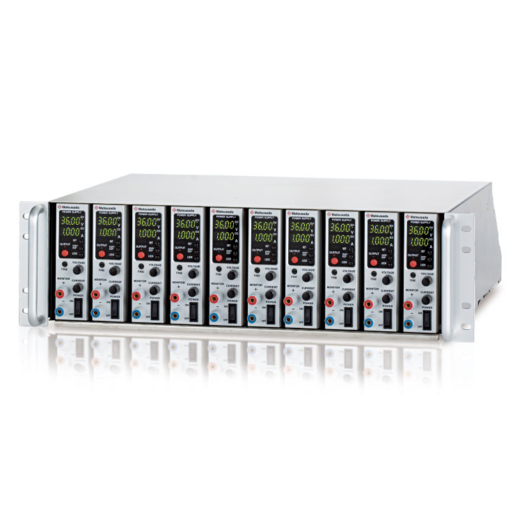
• Rack mount shelf
RME-133H-PK, RME-133H-PK2, RME-133H-PK3
Rack mount shelf for storing power supply units together in a 19-inch rack. The 100 Vac forced cooling fan on the rear panel eliminates the risk of over-temperature. AC200V is also available as an option. Blank panels are also available separately. For details, please refer to the datasheet of the "RMO series" 19-inch rack mount shelf.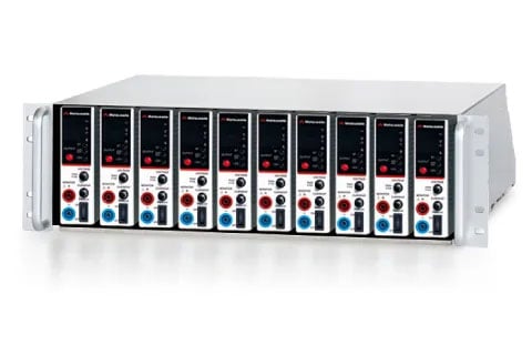
- Application software
-
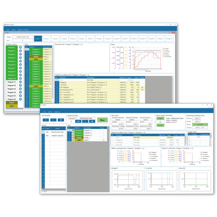
DigiCon-P4KF: Remote control, Test workflow design, and Data logging
DigiCon is an application software that remotely controls Matsusada Precision's DC power supplies connected via LAN. The software can control multiple power supplies simultaneously or individually. -
- Power control for PRKT, PRT/PRTM, PBR/PBRM, P4KF, PKTS, HARS series
- Full remote control available
- Consists of "configuration software" and "operation software
- Linkage to digital multimeters, data loggers, and thermostatic chambers is possible.
- Easy operation with Graphical User Interface (GUI)
- Automatic Test Equipment (ATE) can be built without programming knowledge.
- Real-time logging, graphing, and data storage

Download
If you are unable to download a file
Please try the following solution.
- Please press Ctrl+F5 to clear the cache of your web browser and try again.
- Please restart your web browser and log in again to try again.
- Please change your web browser to another browser and try again.
- Restart the computer and try again.
- Please try again on a different computer.

-
P4KF-80 series Datasheet
Date: 2026-02-19 rev 10
PDF (4,735 KB)
-
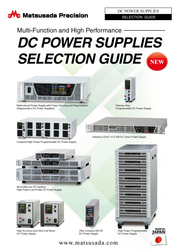
DC POWER SUPPLIES SELECTION GUIDE
Date: 2025-06-27 rev.02
PDF (5,265 KB)

-
How to Use DC Power Supplies
Date: 2025-11-11 rev 09
PDF (1,281 KB)

-
P4KF-80 series Instruction Manual
Date: 2025-05-14 rev 0.1
PDF (3,789 KB)
-
P4KF-80 series Basic Instruction Manual (Japanese and English)
Date: 2025-05-14 rev 0.2
PDF (1,092 KB)
-
DigiCon Instruction Manual
Date: 2025-03-25 rev 0.2
PDF (4,541 KB)

-
P4KF-80 series Outline Drawing (DXF, PDF)
Date: 2024-07-31
ZIP (343 KB)
-
P4KF-80 3D MODELS (STEP, IGES)
Date: 2025-02-03
ZIP (6,840 KB)
Login Required
-
P4KF-80 series Datasheet
Date: 2026-02-19 rev 10
PDF (4,735 KB)
-
DC POWER SUPPLIES SELECTION GUIDE
Date: 2025-06-27 rev.02
PDF (5,265 KB)
-
How to Use DC Power Supplies
Date: 2025-11-11 rev 09
PDF (1,281 KB)
-
P4KF-80 series Instruction Manual
Date: 2025-05-14 rev 0.1
PDF (3,789 KB)
-
P4KF-80 series Basic Instruction Manual (Japanese and English)
Date: 2025-05-14 rev 0.2
PDF (1,092 KB)
-
DigiCon Instruction Manual
Date: 2025-03-25 rev 0.2
PDF (4,541 KB)
-
P4KF-80 series Outline Drawing (DXF, PDF)
Date: 2024-07-31
ZIP (343 KB)
-
P4KF-80 3D MODELS (STEP, IGES)
Date: 2025-02-03
ZIP (6,840 KB)
On this website, we provide only the latest versions of information and instruction manuals for our products. Therefore, the newest versions of manuals on the website may differ from those that came with products you purchased in the past.