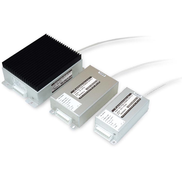
INPUT/OUTPUT PROPORTIONAL HIGH VOLTAGE POWER SUPPLY
Well-shielded compact module
- Max Voltage: 0.3kV to 25kV
- Max Current: 0.1mA to 20mA
- Ultra-compact
- Lightweight
Suitable for Photomultiplier Tube, Microchannel plate and Radiation counter applications
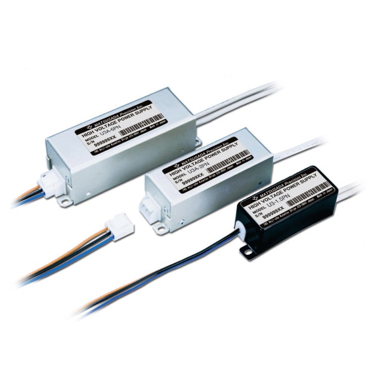
The input/output proportional module is an embedded high voltage module designed for OEM applications.
It is ideal for applications with small load regulation such as Photomultiplier Tubes (PMTs), Microchannel Plates (MCPs), and radiation detectors.
In addition, models below 6 kV featuring the voltage isolation between the primary and secondary sides are available for floating applications.
With the output up to 25 kV/10 W, "high performance" as well as “general purpose" depending on the performance of the ripple value, we provide you with most suitable models in a wide lineup for your needs.
FEATURES AND BENEFITS
- Ultra-compact, Light-weight, and Input/Output proportional
- Output voltage Proportional to Input voltage
- Low noise
- High reliability
- Input/Output isolated (Models up to 6 kV)
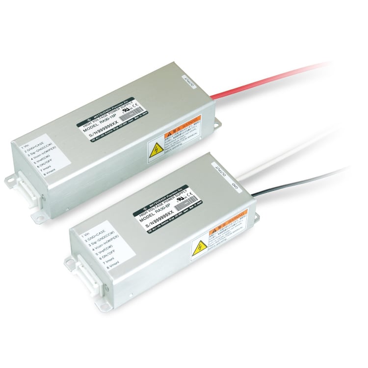
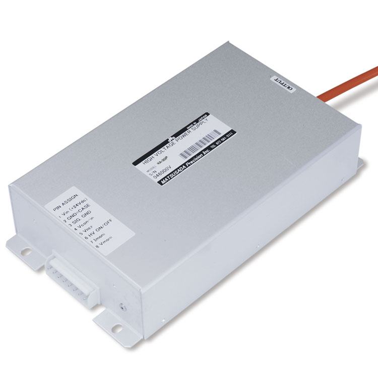
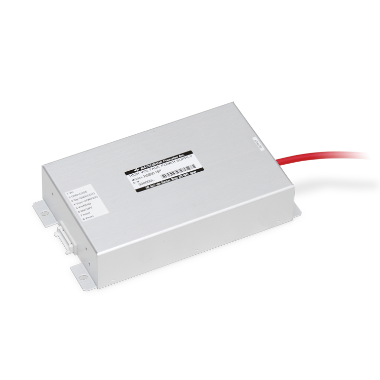
- Detachable input connector (Models except for case of C1)
- Aluminum case (Models except for case of C1)
APPLICATIONS
Models
U3 series (3 watts)
| Model | Output | Minimum Load | Ripple | I/O Isolation * [Vdc] | |
|---|---|---|---|---|---|
| Voltage | Current | ||||
| U3-0.3PN | +0.02 to +0.3/-0.02 to -0.3 kV | 10 mA | 0.03 MΩ | 0.12 %p-p | 2000 V |
| U3-0.6PN | +0.04 to +0.6/-0.04 to -0.6 kV | 5 mA | 0.12 MΩ | ||
| U3-1.1PN | +0.1 to +1.1/-0.1 to -1.1 kV | 2.75 mA | 0.4 MΩ | ||
| U3-1.5PN | +0.1 to +1.5/-0.1 to -1.5 kV | 2 mA | 0.75 MΩ | ||
| U3A-2PN | +0.2 to +2/-0.2 to -2 kV | 1.5 mA | 1.3 MΩ | 2500 V | |
| U3A-3PN | +0.2 to +3/-0.2 to -3 kV | 1 mA | 3 MΩ | 3500 V | |
| U3A-6PN | +0.4 to +6/-0.4 to -6 kV | 0.5 mA | 12 MΩ | 0.15 %p-p | 7000 V |
| Model | Output | Minimum Load | Ripple | I/O Isolation * [Vdc] | |
|---|---|---|---|---|---|
| Voltage | Current | ||||
| U3A-10P | 0.8 to 10 kV | 0.25 mA | 40 MΩ | 0.05 %p-p | - |
| U3A-15P | 1.2 to 15 kV | 0.2 mA | 75 MΩ | ||
| U3A-25P | 2 to 25 kV | 0.1 mA | 250 MΩ | ||
| Model | Output | Minimum Load | Ripple | I/O Isolation * [Vdc] | |
|---|---|---|---|---|---|
| Voltage | Current | ||||
| U3A-10N | -0.8 to -10 kV | 0.25 mA | 40 MΩ | 0.05 %p-p | - |
| U3A-15N | -1.2 to -15 kV | 0.2 mA | 75 MΩ | ||
| U3A-25N | -2 to -25 kV | 0.1 mA | 250 MΩ | ||
* I/O Isolation: The withstand voltage is the voltage value including the output voltage too.
U6 series (6 watts)
| Model | Output | Minimum Load | Ripple | I/O Isolation * [Vdc] | |
|---|---|---|---|---|---|
| Voltage | Current | ||||
| U6A-0.3PN | +0.03 to +0.3/-0.03 to -0.3 kV | 20 mA | 0.015 MΩ | 0.15 %p-p | 2000 V |
| U6A-0.6PN | +0.05 to +0.6/-0.05 to -0.6 kV | 10 mA | 0.06 MΩ | ||
| U6A-1.1PN | +0.1 to +1.1/-0.1 to -1.1 kV | 5.5 mA | 0.2 MΩ | ||
| U6A-1.5PN | +0.1 to +1.5/-0.1 to -1.5 kV | 4 mA | 0.38 MΩ | ||
| U6A-2PN | +0.2 to +2/-0.2 to -2 kV | 3 mA | 0.65 MΩ | 0.2 %p-p | 2500 V |
| U6A-3PN | +0.2 to +3/-0.2 to -3 kV | 2 mA | 1.5 MΩ | 3500 V | |
| U6A-6PN | +0.3 to +6/-0.3 to -6 kV | 1 mA | 6 MΩ | 7000 V | |
| Model | Output | Minimum Load | Ripple | I/O Isolation * [Vdc] | |
|---|---|---|---|---|---|
| Voltage | Current | ||||
| U6A-10P | 0.5 to 10 kV | 0.5 mA | 20 MΩ | 0.05 %p-p | - |
| U6A-15P | 0.8 to 15 kV | 0.4 mA | 37 MΩ | ||
| U6A-25P | 1.4 to 25 kV | 0.2 mA | 125 MΩ | ||
| Model | Output | Minimum Load | Ripple | I/O Isolation * [Vdc] | |
|---|---|---|---|---|---|
| Voltage | Current | ||||
| U6A-10N | -0.5 to -10 kV | 0.5 mA | 20 MΩ | 0.05 %p-p | - |
| U6A-15N | -0.8 to -15 kV | 0.4 mA | 37 MΩ | ||
| U6A-25N | -1.4 to -25 kV | 0.2 mA | 125 MΩ | ||
* I/O Isolation: The withstand voltage is the voltage value including the output voltage too.
U10 series (10 watts)
| Model | Output | Minimum Load | Ripple | I/O Isolation * [Vdc] | |
|---|---|---|---|---|---|
| Voltage | Current | ||||
| U10A-0.6PN | +0.06 to +0.6/-0.06 to -0.6 kV | 15 mA | 0.04 MΩ | 0.1 %p-p | 2000 V |
| U10A-1.1PN | +0.1 to +1.1/-0.1 to -1.1 kV | 10 mA | 0.11 MΩ | 0.15 %p-p | |
| U10A-1.5PN | +0.15 to +1.5/-0.15 to -1.5 kV | 8 mA | 0.19 MΩ | ||
| U10A-2PN | +0.2 to +2/-0.2 to -2 kV | 6 mA | 0.33 MΩ | 0.2 %p-p | 2500 V |
| U10A-3PN | +0.3 to +3/-0.3 to -3 kV | 4 mA | 0.95 MΩ | 0.2 %p-p | 3500 V |
| U10A-6PN | +0.6 to +6/-0.6 to -6 kV | 2 mA | 3 MΩ | 0.3 %p-p | 7000 V |
| Model | Output | Minimum Load | Ripple | I/O Isolation * [Vdc] | |
|---|---|---|---|---|---|
| Voltage | Current | ||||
| U10A-10P | 1 to 10 kV | 1 mA | 10 MΩ | 0.2 %p-p | - |
| U10A-15P | 0.15 to 15 kV | 0.6 mA | 25 MΩ | 0.08 %p-p | |
| U10A-25P | 2.4 to 25 kV | 0.33 mA | 75 MΩ | ||
| Model | Output | Minimum Load | Ripple | I/O Isolation * [Vdc] | |
|---|---|---|---|---|---|
| Voltage | Current | ||||
| U10A-10N | -1 to -10 kV | 1 mA | 10 MΩ | 0.2 %p-p | - |
| U10A-15N | -0.15 to -15 kV | 0.6 mA | 25 MΩ | 0.08 %p-p | |
| U10A-25N | -2.4 to -25 kV | 0.33 mA | 75 MΩ | ||
* I/O Isolation: The withstand voltage is the voltage value including the output voltage too.
Specifications
Options
Accessory
- CN3U, CU8U
-
Assembled input connector
Connector 0.25 meters flying wires
Models with Case C2, C3, and C4: CN3U
Models with Case C5, C6: CN8U
Diagram
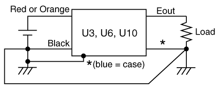
Connection Diagram
Dimensions
Others
Application notes
General Use
- For models 6 kV or less, the case (blue lead wire), input (black lead wire), and output are not connected internally. For safety reasons, always connect the case, input, and output to the ground.
- For models 10 kV or more, the case (no lead wire) and input (black lead wire) are internally connected. For safety reasons, always connect the input to the ground. The * part in the figure below is not present on models of 10 kV or more.
- If the output is used as floating, refer to Floating Use with High-voltage.
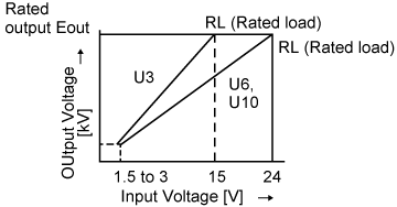
- U3: up to 15 V
- U6, U10: up to 24 V
- Make sure that the wiring is properly connected to the product as shown in the figure above before operating the product.
- Apply the specified input voltage and set the voltage.
- Models of U3, 6 kV or less, do not have a discharge resistor built into the output. When using such a model with capacitive loads, etc., install a discharge resistor in the output.
- When quitting the operation of the product, turn off the input power.
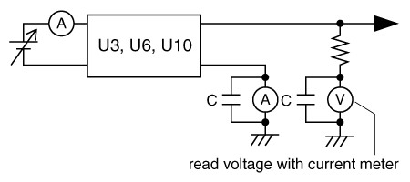
Monitoring Output Voltage/Current
- C = 0.1 to 1 µF pass capacitor
- Instead of using a voltmeter or ammeter, inserting a resistor as shown in the figure and measuring the voltage at both ends of the resistor with a DVM.
Parallel Operation to Increase Output Current
- Valid only for the same model
- Do not parallel different models.

Reducing Output Ripple
- L = 1 m to 5 mH: A resistor is also available.
- C = 0.01 µF to 0.1 µF: Pay attention to withstand voltage.

Suppressing Input Ripple to Reduce effect to Input Power Source
- Ground at one point.
- L = 100 µH or more
- C = 100 µF/35 V or more

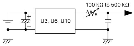
Generating Required Input Voltage for Output Voltage
When load regulation is large.
This circuit can also reduce the noise generated on the input power source.

When load regulation is small.
Install a capacitor with approx. 0.01 µF to 0.1 µF on the output side to reduce the ripple on the output voltage.
Pay attention to withstand voltage.
Floating Use with High-voltage
- Models of 6 kV or less are input/output isolated, therefore they can be used with the output floating.
- For models of 6 kV or less, the case (blue lead wire), input (black lead wire), and output are not connected internally.
- For safety reasons, always connect the case and input to the ground.
- U3: up to 15 V
- U6, U10: up to 24 V
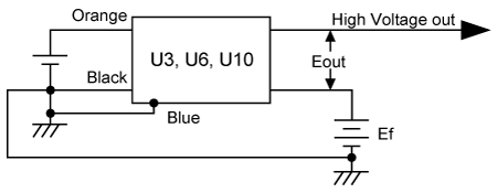

The Ef + Eout is less than or equal to the value of "I/O Isolation" shown on the Models.
- Make sure that the wiring is properly connected to the product as shown in the figure above before operating the product.
- Apply the specified input voltage and set the voltage.
- When floating the output, lower the Ef impedance because the common-mode noise may occur.
- When quitting the operation of the product, turn off the input power.
NOTE
- This product is an embedded power supply, which has been designed and produced with full consideration for high-voltage safety. For further safety, ground it according to General Use and Floating Use with High-voltage.
- Avoid short-circuiting the load for long periods of time.
- Do not touch the output just after turning the product off, because high voltage may still present at the output. If you need to touch it, check with a voltmeter or similar device that the output voltage has dropped sufficiently, or wait until at least 20 minutes have passed. If the load is an open or capacitive load, the output voltage may not drop for a long time, so if you must touch it, be sure to discharge the output.
INPUT/OUTPUT PROPORTIONAL CHARACTERISTICS
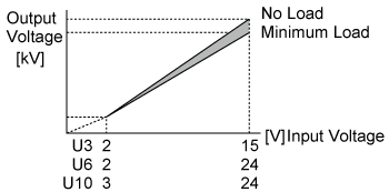
Calculation Formula of Input Voltage to Output Voltage

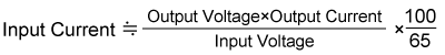
Calculation Formula of Input Current
See the calculation at an efficiency of approximately 65%.
Download
If you are unable to download a file
Please try the following solution.
- Please press Ctrl+F5 to clear the cache of your web browser and try again.
- Please restart your web browser and log in again to try again.
- Please change your web browser to another browser and try again.
- Restart the computer and try again.
- Please try again on a different computer.
-
U3/U6/U10 series Datasheet
Date: 2023-12-25 rev.09
PDF (1,192 KB)
-
High Voltage Power Supply Modules Selection Guide
Date: 2024-03-04 rev.11
PDF (4,559 KB)
-
Safety and Usage of High voltage Power supply
Date: 2023-07-27 rev. 03
PDF (602 KB)
The account registration is necessary for downloading
-
U3/U6/U10 series Datasheet
Date: 2023-12-25 rev.09
PDF (1,192 KB)
-
High Voltage Power Supply Modules Selection Guide
Date: 2024-03-04 rev.11
PDF (4,559 KB)
-
Safety and Usage of High voltage Power supply
Date: 2023-07-27 rev. 03
PDF (602 KB)
In this website, we provide only the latest version of information including instruction manuals as of our products. Therefore, the newest versions of manuals on the website might be not same as the ones of products you purchased in the past.