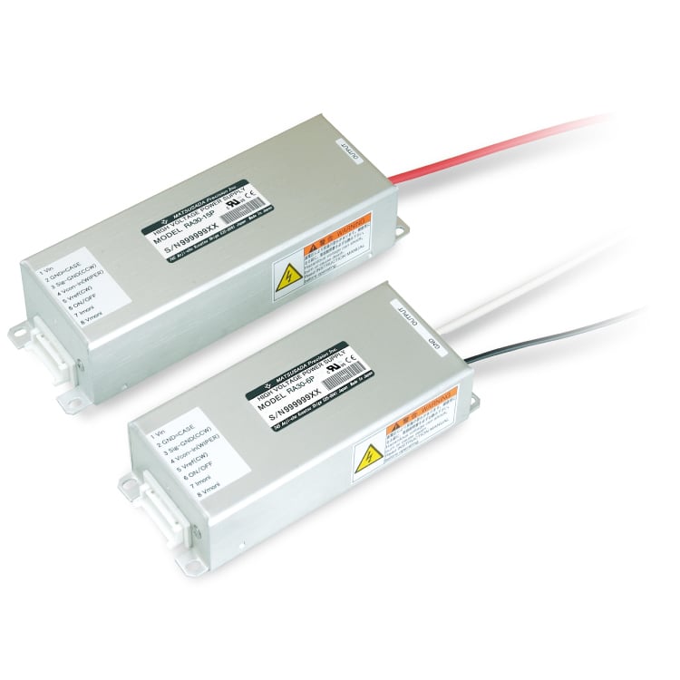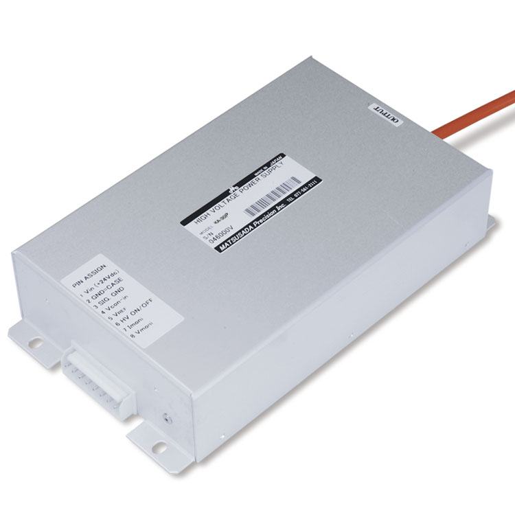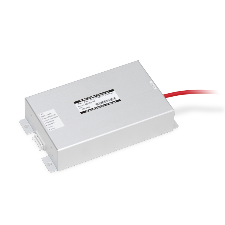
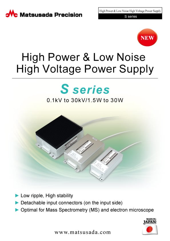
HIGH POWER & LOW NOISE HIGH VOLTAGE POWER SUPPLY
- Voltage: 0.6 to 30kV
- Current: 0.08 to 50mA
- Power: 1.5 to 30W
- Detachable input connector
Optimal for Mass Spectrometry (MS) and electron microscope
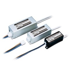
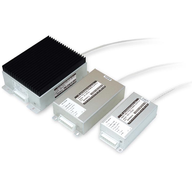
S series is an embedded high voltage module available for a broad range of applications from OEM to the laboratory.
They are an excellent choice when you require a highly stable output for use of Mass Spectrometry (MS) and microscopic analysis. It is also ideal for applications with some load regulation. And, the series is available for a wide range of use that can control using either an external control voltage or external variable resistor and come with optional output voltage monitor. Featuring a diverse range of models up to 30 kV/30 W, and high-performance as well as general types, you can find best solution for nearly every requirement.
FEATURES AND BENEFITS
- Low noise, High stability
- Aluminum case
- Detachable input connector
- Compact and lightweight
- External potentiometer or External voltage enabling output control
APPLICATIONS
- Electrostatic Chuck (E-Chuck, ESC)
- High Voltage test (dielectric strength test, hipot test, etc.)
Models
| Model | Output | Ripple | Regulation | |||
|---|---|---|---|---|---|---|
| Voltage | Current | Power | Line | Load | ||
| S1-0.6P | 0 to 0.6 kV | 2.5 mA | 1.5 W | 0.008 %p-p | ±0.005 % | 0.005 % |
| S3-0.6P | 5 mA | 3 W | ||||
| S6-0.6P | 10 mA | 6 W | ||||
| S15-0.6P | 25 mA | 15 W | 0.2 %p-p | ±0.03 % | 0.05 % | |
| S30-0.6P | 50 mA | 30 W | ||||
| S1-1.1P | 0 to 1.1 kV | 1.4 mA | 1.5 W | 0.005 %p-p | ±0.005 % | 0.005 % |
| S3-1.1P | 2.75 mA | 3 W | ||||
| S6-1.1P | 5.5 mA | 6 W | 0.008 %p-p | |||
| S15-1.1P | 12 mA | 15 W | 0.01 %p-p | ±0.03 % | 0.02 % | |
| S30-1.1P | 25 mA | 30 W | 0.03 %p-p | |||
| S1-1.5P | 0 to 1.5 kV | 1 mA | 1.5 W | 0.005 %p-p | ±0.005 % | 0.005 % |
| S3-1.5P | 2 mA | 3 W | ||||
| S6-1.5P | 4 mA | 6 W | 0.008 %p-p | |||
| S15-1.5P | 10 mA | 15 W | 0.01 %p-p | ±0.03 % | 0.02 % | |
| 61.5P | 20 mA | 30 W | 0.03 %p-p | |||
| S1-2P | 0 to 2 kV | 0.75 mA | 1.5 W | 0.005 %p-p | ±0.005 % | 0.005 % |
| S3-2P | 1.5 mA | 3 W | ||||
| S6-2P | 3 mA | 6 W | 0.008 %p-p | |||
| S15-2P | 7.5 mA | 15 W | 0.01 %p-p | ±0.03 % | 0.02 % | |
| S30-2P | 15 mA | 30 W | 0.03 %p-p | |||
| S1-3P | 0 to 3 kV | 0.5 mA | 1.5 W | 0.005 %p-p | ±0.005 % | 0.005 % |
| S3-3P | 1 mA | 3 W | ||||
| S6-3P | 2 mA | 6 W | 0.008 %p-p | |||
| S15-3P | 5 mA | 15 W | 0.01 %p-p | ±0.03 % | 0.02 % | |
| S30-3P | 10 mA | 30 W | 0.03 %p-p | |||
| S1-5P | 0 to 5 kV | 0.3 mA | 1.5 W | 0.005 %p-p | ±0.005 % | 0.005 % |
| S3-5P | 0.6 mA | 3 W | ||||
| S6-5P | 1.2 mA | 6 W | 0.008 %p-p | |||
| S15-5P | 3 mA | 15 W | 0.01 %p-p | ±0.03 % | 0.02 % | |
| S30-5P | 6 mA | 30 W | 0.03 %p-p | |||
| S1-6P | 0 to 6 kV | 0.25 mA | 1.5 W | 0.005 %p-p | ±0.005 % | 0.005 % |
| S3-6P | 0.5 mA | 3 W | ||||
| S6-6P | 1 mA | 6 W | 0.008 %p-p | |||
| S15-6P | 2.5 mA | 15 W | 0.01 %p-p | ±0.03 % | 0.02 % | |
| S30-6P | 5 mA | 30 W | 0.03 %p-p | |||
| S1-10P | 0 to 10 kV | 0.15 mA | 1.5 W | 0.01 %p-p | ±0.01 % | 0.01 % |
| S3-10P | 0.3 mA | 3 W | 0.02 %p-p | |||
| S6-10P | 0.6 mA | 6 W | ||||
| S15-10P | 1.5 mA | 15 W | ±0.03 % | 0.02 % | ||
| S30-10P | 3 mA | 30 W | 0.03 %p-p | |||
| S1-12P | 0 to 12 kV | 0.12 mA | 1.5 W | 0.01 %p-p | ±0.01 % | 0.01 % |
| S3-12P | 0.24 mA | 3 W | 0.02 %p-p | |||
| S6-12P | 0.46 mA | 6 W | ||||
| S15-12P | 1.2 mA | 15 W | ±0.03 % | 0.02 % | ||
| S30-12P | 2.5 mA | 30 W | 0.03 %p-p | |||
| S3-15P | 0 to 15 kV | 0.2 mA | 3 W | 0.02 %p-p | ±0.01 % | 0.01 % |
| S6-15P | 0.36 mA | 6 W | ||||
| S15-15P | 1 mA | 15 W | ±0.03 % | 0.02 % | ||
| S30-15P | 2 mA | 30 W | 0.03 %p-p | |||
| S3-20P | 0 to 20 kV | 0.13 mA | 3 W | 0.02 %p-p | ±0.01 % | 0.01 % |
| S6-20P | 0.26 mA | 6 W | ||||
| S15-20P | 0.75 mA | 15 W | ±0.03 % | 0.02 % | ||
| S30-20P | 1.5 mA | 30 W | 0.03 %p-p | |||
| S3-25P | 0 to 25 kV | 0.1 mA | 3 W | 0.02 %p-p | ±0.01 % | 0.01 % |
| S6-25P | 0.2 mA | 6 W | ||||
| S15-25P | 0.6 mA | 15 W | ±0.03 % | 0.02 % | ||
| S30-25P | 1.2 mA | 30 W | 0.03 %p-p | |||
| S3-30P | 0 to 30 kV | 0.08 mA | 3 W | 0.02 %p-p | ±0.01 % | 0.01 % |
| S6-30P | 0.16 mA | 6 W | ||||
| S15-30P | 0.5 mA | 15 W | ±0.03 % | 0.02 % | ||
| S30-30P | 1 mA | 30 W | 0.03 %p-p | |||
| Model | Output | Ripple | Regulation | |||
|---|---|---|---|---|---|---|
| Voltage | Current | Power | Line | Load/ | ||
| S1-0.6N | 0 to -0.6 kV | 2.5 mA | 1.5 W | 0.008 %p-p | ±0.005 % | 0.005 % |
| S3-0.6N | 5 mA | 3 W | ||||
| S6-0.6N | 10 mA | 6 W | ||||
| S15-0.6N | 25 mA | 15 W | 0.2 %p-p | ±0.03 % | 0.05 % | |
| S30-0.6N | 50 mA | 30 W | ||||
| S1-1.1N | 0 to -1.1 kV | 1.4 mA | 1.5 W | 0.005 %p-p | ±0.005 % | 0.005 % |
| S3-1.1N | 2.75 mA | 3 W | ||||
| S6-1.1N | 5.5 mA | 6 W | 0.008 %p-p | |||
| S15-1.1N | 12 mA | 15 W | 0.01 %p-p | ±0.03 % | 0.02 % | |
| S30-1.1N | 25 mA | 30 W | 0.03 %p-p | |||
| S1-1.5N | 0 to -1.5 kV | 1 mA | 1.5 W | 0.005 %p-p | ±0.005 % | 0.005 % |
| S3-1.5N | 2 mA | 3 W | ||||
| S6-1.5N | 4 mA | 6 W | 0.008 %p-p | |||
| S15-1.5N | 10 mA | 15 W | 0.01 %p-p | ±0.03 % | 0.02 % | |
| S30-1.5N | 20 mA | 30 W | 0.03 %p-p | |||
| S1-2N | 0 to -2 kV | 0.75 mA | 1.5 W | 0.005 %p-p | ±0.005 % | 0.005 % |
| S3-2N | 1.5 mA | 3 W | ||||
| S6-2N | 3 mA | 6 W | 0.008 %p-p | |||
| S15-2N | 7.5 mA | 15 W | 0.01 %p-p | ±0.03 % | 0.02 % | |
| S30-2N | 15 mA | 30 W | 0.03 %p-p | |||
| S1-3N | 0 to -3 kV | 0.5 mA | 1.5 W | 0.005 %p-p | ±0.005 % | 0.005 % |
| S3-3N | 1 mA | 3 W | ||||
| S6-3N | 2 mA | 6 W | 0.008 %p-p | |||
| S15-3N | 5 mA | 15 W | 0.01 %p-p | ±0.03 % | 0.02 % | |
| S30-3N | 10 mA | 30 W | 0.03 %p-p | |||
| S1-5N | 0 to -5 kV | 0.3 mA | 1.5 W | 0.005 %p-p | ±0.005 % | 0.005 % |
| S3-5N | 0.6 mA | 3 W | ||||
| S6-5N | 1.2 mA | 6 W | 0.008 %p-p | |||
| S15-5N | 3 mA | 15 W | 0.01 %p-p | ±0.03 % | 0.02 % | |
| S30-5N | 6 mA | 30 W | 0.03 %p-p | |||
| S1-6N | 0 to -6 kV | 0.25 mA | 1.5 W | 0.005 %p-p | ±0.005 % | 0.005 % |
| S3-6N | 0.5 mA | 3 W | ||||
| S6-6N | 1 mA | 6 W | 0.008 %p-p | |||
| S15-6N | 2.5 mA | 15 W | 0.01 %p-p | ±0.03 % | 0.02 % | |
| S30-6N | 5 mA | 30 W | 0.03 %p-p | |||
| S1-10N | 0 to -10 kV | 0.15 mA | 1.5 W | 0.01 %p-p | ±0.01 % | 0.01 % |
| S3-10N | 0.3 mA | 3 W | 0.02 %p-p | |||
| S6-10N | 0.6 mA | 6 W | ||||
| S15-10N | 1.5 mA | 15 W | ±0.03 % | 0.02 % | ||
| S30-10N | 3 mA | 30 W | 0.03 %p-p | |||
| S1-12N | 0 to -12 kV | 0.12 mA | 1.5 W | 0.01 %p-p | ±0.01 % | 0.01 % |
| S3-12N | 0.24 mA | 3 W | 0.02 %p-p | |||
| S6-12N | 0.46 mA | 6 W | ||||
| S15-12N | 1.2 mA | 15 W | ±0.03 % | 0.02 % | ||
| S30-12N | 2.5 mA | 30 W | 0.03 %p-p | |||
| S3-15N | 0 to -15 kV | 0.2 mA | 3 W | 0.02 %p-p | ±0.01 % | 0.01 % |
| S6-15N | 0.36 mA | 6 W | ||||
| S15-15N | 1 mA | 15 W | ±0.03 % | 0.02 % | ||
| S30-15N | 2 mA | 30 W | 0.03 %p-p | |||
| S3-20N | 0 to -20 kV | 0.13 mA | 3 W | 0.02 %p-p | ±0.01 % | 0.01 % |
| S6-20N | 0.26 mA | 6 W | ||||
| S15-20N | 0.75 mA | 15 W | ±0.03 % | 0.02 % | ||
| S30-20N | 1.5 mA | 30 W | 0.03 %p-p | |||
| S3-25N | 0 to -25 kV | 0.1 mA | 3 W | 0.02 %p-p | ±0.01 % | 0.01 % |
| S6-25N | 0.2 mA | 6 W | ||||
| S15-25N | 0.6 mA | 15 W | ±0.03 % | 0.02 % | ||
| S30-25N | 1.2 mA | 30 W | 0.03 %p-p | |||
| S3-30N | 0 to -30 kV | 0.08 mA | 3 W | 0.02 %p-p | ±0.01 % | 0.01 % |
| S6-30N | 0.16 mA | 6 W | ||||
| S15-30N | 0.5 mA | 15 W | ±0.03 % | 0.02 % | ||
| S30-30N | 1 mA | 30 W | 0.03 %p-p | |||
Specifications
Options
- -L2
-
Voltage monitor output
up to 6 kV: 1 V@1 kV
10 k to 30 kV: 1 V@10 kV
Accuracy ±2.5% F.S.
For details, download the datasheet below.
How to Order
When ordering, add Option No. to Model No.
Example: S1-6P-L2
Accessory (sold separately)
- CN8R
-
Assembled input connector
Assembled input connector with 9.84 inches (250 mm) flying leads
Diagram
Dimensions
Download
If you are unable to download a file
Please try the following solution.
- Please press Ctrl+F5 to clear the cache of your web browser and try again.
- Please restart your web browser and log in again to try again.
- Please change your web browser to another browser and try again.
- Restart the computer and try again.
- Please try again on a different computer.
-
S series Datasheet
Date: 2024-04-25 rev.12
PDF (997 KB)
-
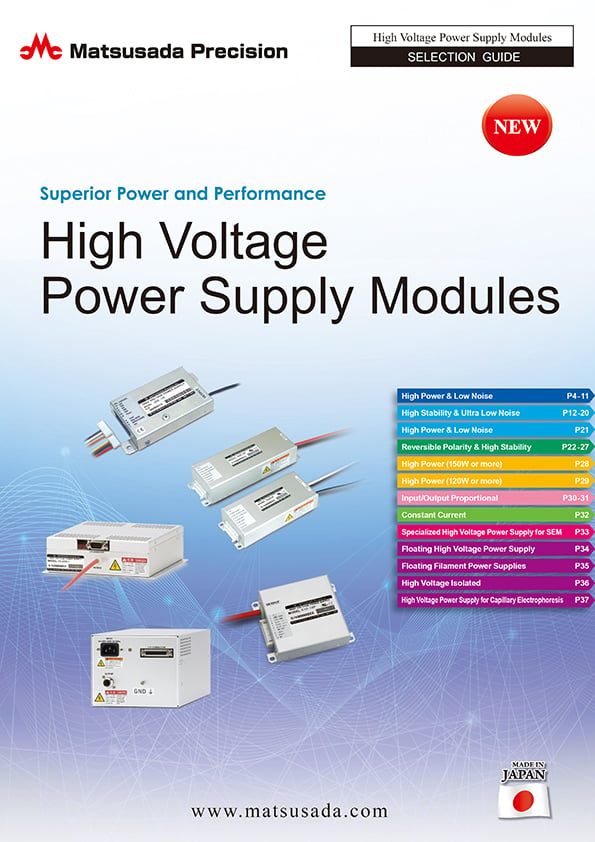
High Voltage Power Supply Modules Selection Guide
Date: 2024-03-04 rev.11
PDF (4,559 KB)
-
Safety and Usage of High voltage Power supply
Date: 2023-07-27 rev. 03
PDF (602 KB)
The account registration is necessary for downloading
-
S series Datasheet
Date: 2024-04-25 rev.12
PDF (997 KB)
-
High Voltage Power Supply Modules Selection Guide
Date: 2024-03-04 rev.11
PDF (4,559 KB)
-
Safety and Usage of High voltage Power supply
Date: 2023-07-27 rev. 03
PDF (602 KB)
In this website, we provide only the latest version of information including instruction manuals as of our products. Therefore, the newest versions of manuals on the website might be not same as the ones of products you purchased in the past.