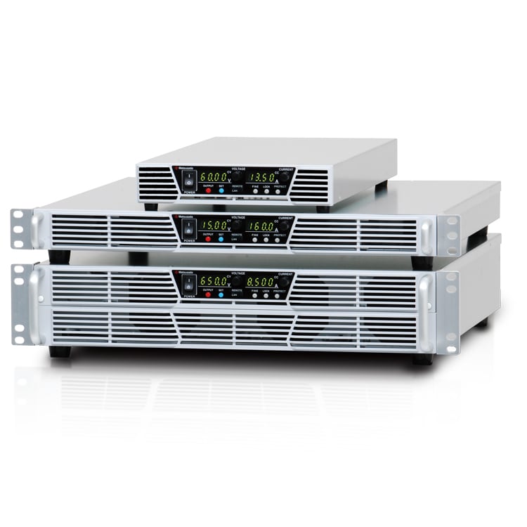
HIGH POWER LOW-PROFILE PROGRAMMABLE DC POWER SUPPLY
- Voltage range: 6V to 650V
- Current: 1.2A to 600A
- Power: 0.75kW to 15kW
- High Power
- Standard Interface
LAN, USB(TMC), RS-485 
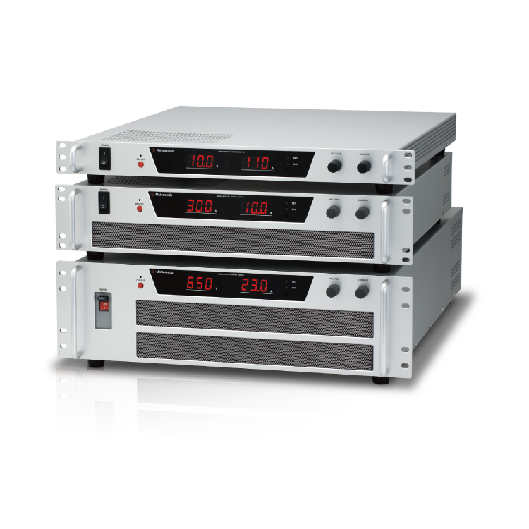
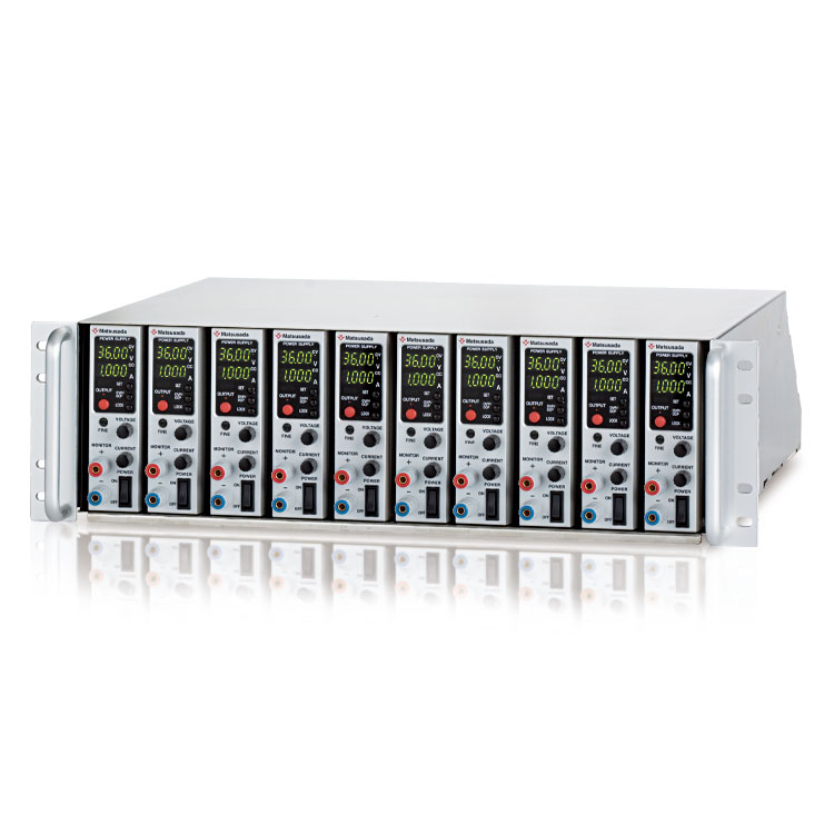
COMPACT CVCC PROGRAMMABLE AND VARIABLE DC POWER SUPPLY
The PVCE/PVCEJ series, a low profile DC power supply focusing exclusively on “a broad range of lineup” and “high reliability,” offers high performance as well as high power. Achieving high-efficiency noise reduction with our unique low-noise switching method, the PVCE/PVCEJ is suitable for high-density rack mounting. With a wide variety of applications, we assure you that the PVCE/PVCEJ series is perfect for fully supporting your research and development.
(All models are CE marking. Some models are UL60950-1 recognized products.)
The product is designed to be installed in the customer’s system and so as to meet the requirements of CE marking regarding chassis mounting, noise control, proper protections, and isolated devices. It is not designed to perform alone.
FEATURES AND BENEFITS
- Compact and high power Max 15 kW
- Ideal for research and development with low noise switching method.
- PFC circuit and universal input wound not select the place of operation.
- Various operations by connecting multiple power supplies, such as master/slave, is possible.
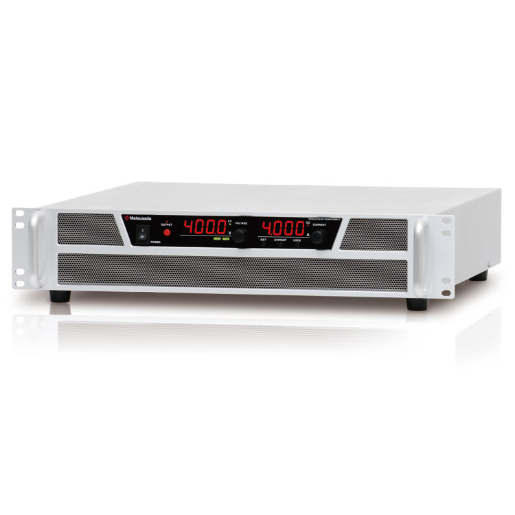
- PVCE/PVCEJ adopt large four-digit monitor display for both voltage and current, which contributes to precise monitoring with better recognition.
- Operability and safety are improved with new features of key-lock function and acceleration rotary encoder, that increment will vary by speed of rotation.
APPLICATIONS
-
Test and Measurement
Test and measurement for electronic parts, equipment, printed circuit boards (PCB)
-
Automated Test Equipment (ATE)
Automated test equipment (ATE) for automotive instruments, various electronic components, etc.
-
Semiconductor Processing
Semiconductor manufacturing equipment such as Photolithography, Deposition, Ion implantation DC power supplies for RF, electromagnets, beam steering, and heaters
-
Burn-in Testing
Burn-in Testing for semiconductor devices and electronic components
-
Renewable Energy
Development of Hydrogen and Ammonia production equipment, Fuel cells, Solar cells, Secondary cells, Wind turbine, Power inverters, DC-DC converters
-
Scientific Research, Medical Equipment, etc
The PVCE/PVCEJ series has been designed to suit a wide variety of DC power supply needs.
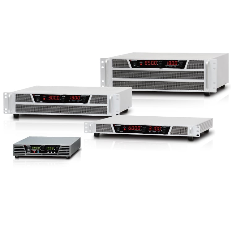
Models
PVCEJ series is applied to a half-rack width, and PVCE series goes with a 19 inches rack.
Half: half-rack width
| Model | Maximum Output | Safety Standards | ||
|---|---|---|---|---|
| Voltage | Current | Power | ||
| HalfPVCEJ6-130 | 6 V | 130 A | 0.78 kW |   |
| PVCE6-130 | 130 A | 0.78 kW | |
|
| PVCE6-220 | 220 A | 1.3 kW | |
|
| PVCE6-310 | 310 A | 1.8 kW | |
|
| PVCE6-530 | 530 A | 3.2 kW | |
|
| HalfPVCEJ8-100 | 8 V | 100 A | 0.8 kW | |
| PVCE8-100 | 100 A | 0.8 kW | |
|
| PVCE8-180 | 180 A | 1.4 kW | |
|
| PVCE8-300 | 300 A | 2.4 kW | |
|
| PVCE8-400 | 400 A | 3.2 kW | |
|
| PVCE8-600 | 600 A | 4.8 kW | |
|
| HalfPVCEJ10-80 | 10 V | 80 A | 0.8 kW | |
| PVCE10-80 | 80 A | 0.8 kW | |
|
| PVCE10-150 | 150 A | 1.5 kW | |
|
| PVCE10-240 | 240 A | 2.4 kW | |
|
| PVCE10-340 | 340 A | 3.4 kW | |
|
| PVCE10-510 | 510 A | 5.1 kW | |
|
| HalfPVCEJ12.5-64 | 12.5 V | 64 A | 0.8 kW | |
| PVCE12.5-64 | 64 A | 0.8 kW | |
|
| PVCE12.5-120 | 120 A | 1.5 kW | |
|
| PVCE12.5-190 | 190 A | 2.4 kW | |
|
| HalfPVCEJ15-54 | 15 V | 54 A | 0.81 kW | |
| PVCE15-54 | 54 A | 0.81 kW | |
|
| PVCE15-100 | 100 A | 1.5 kW | |
|
| PVCE15-160 | 160 A | 2.4 kW | |
|
| PVCE15-227 | 227 A | 3.4 kW | |
|
| PVCE15-340 | 340 A | 5.1 kW | |
|
| HalfPVCEJ16-50 | 16 V | 50 A | 0.8 kW | |
| PVCE16-50 | 50 A | 0.8 kW | |
|
| PVCE16-95 | 95 A | 1.5 kW | |
|
| PVCE16-150 | 150 A | 2.4 kW | |
|
| PVCE16-220 | 220 A | 3.5 kW | |
|
| PVCE16-320 | 320 A | 5.1 kW | |
|
| HalfPVCEJ20-40 | 20 V | 40 A | 0.8 kW | |
| PVCE20-40 | 40 A | 0.8 kW | |
|
| PVCE20-80 | 80 A | 1.6 kW | |
|
| PVCE20-125 | 125 A | 2.5 kW | |
|
| PVCE20-170 | 170 A | 3.4 kW | |
|
| PVCE20-260 | 260 A | 5.2 kW | |
|
| HalfPVCEJ30-27 | 30 V | 27 A | 0.81 kW | |
| PVCE30-27 | 27 A | 0.81 kW | |
|
| PVCE30-53 | 53 A | 1.6 kW | |
|
| PVCE30-84 | 84 A | 2.5 kW | |
|
| PVCE30-115 | 115 A | 3.5 kW | |
|
| PVCE30-180 | 180 A | 5.4 kW | |
|
| PVCE35-45 | 35 V | 45 A | 1.6 kW | |
| PVCE35-72 | 72 A | 2.5 kW | |
|
| HalfPVCEJ40-20 | 40 V | 20 A | 0.8 kW | |
| PVCE40-20 | 20 A | 0.8 kW | |
|
| PVCE40-40 | 40 A | 1.6 kW | |
|
| PVCE40-62 | 62 A | 2.4 kW | |
|
| PVCE40-85 | 85 A | 3.4 kW | |
|
| PVCE40-130 | 130 A | 5.2 kW | |
|
| PVCE40-250 Coming soon | 250 A | 10 kW | |
|
| HalfPVCEJ45-18 | 45 V | 18 A | 0.81 kW | |
| PVCE45-18 | 18 A | 0.81 kW | |
|
| PVCE45-35 | 35 A | 1.5 kW | |
|
| PVCE45-55 | 55 A | 2.4 kW | |
|
| PVCE45-78 | 78 A | 3.5 kW | |
|
| PVCE45-120 | 120 A | 5.4 kW | |
|
| PVCE50-31 | 50 V | 31 A | 1.5 kW | |
| HalfPVCEJ60-13.5 | 60 V | 13.5 A | 0.81 kW | |
| PVCE60-13.5 | 13.5 A | 0.81 kW | |
|
| PVCE60-26 | 26 A | 1.5 kW | |
|
| PVCE60-42 | 42 A | 2.5 kW | |
|
| PVCE60-60 | 60 A | 3.6 kW | |
|
| PVCE60-90 | 90 A | 5.4 kW | |
|
| HalfPVCEJ80-10 | 80 V | 10 A | 0.8 kW | |
| PVCE80-10 | 10 A | 0.8 kW | |
|
| PVCE80-20 | 20 A | 1.6 kW | |
|
| PVCE80-31 | 31 A | 2.4 kW | |
|
| PVCE80-45 | 45 A | 3.6 kW | |
|
| PVCE80-68 | 68 A | 5.4 kW | |
|
| HalfPVCEJ100-8 | 100 V | 8 A | 0.8 kW | |
| PVCE100-8 | 8 A | 0.8 kW | |
|
| PVCE100-16 | 16 A | 1.6 kW | |
|
| PVCE100-25 | 25 A | 2.5 kW | |
|
| PVCE100-36 | 36 A | 3.6 kW | |
|
| PVCE100-55 | 55 A | 5.5 kW | |
|
| HalfPVCEJ120-6.6 | 120 V | 6.6 A | 0.79 kW | |
| PVCE120-6.6 | 6.6 A | 0.79 kW | |
|
| HalfPVCEJ150-5 | 150 V | 5 A | 0.75 kW | |
| PVCE150-5 | 5 A | 0.75 kW | |
|
| PVCE150-10 | 10 A | 1.5 kW | |
|
| PVCE150-16.6 | 16.6 A | 2.5 kW | |
|
| PVCE150-24 | 24 A | 3.6 kW | |
|
| PVCE150-36 | 36 A | 5.4 kW | |
|
| HalfPVCEJ160-5 | 160 V | 5 A | 0.8 kW | |
| PVCE160-5 | 5 A | 0.8 kW | |
|
| HalfPVCEJ200-4 | 200 V | 4 A | 0.8 kW | |
| PVCE200-4 | 4 A | 0.8 kW | |
|
| PVCE200-8 | 8 A | 1.6 kW | |
|
| PVCE200-12.5 | 12.5 A | 2.5 kW | |
|
| PVCE200-18 | 18 A | 3.6 kW | |
|
| PVCE200-27 | 27 A | 5.4 kW | |
|
| HalfPVCEJ250-3.2 | 250 V | 3.2 A | 0.8 kW | |
| PVCE250-3.2 | 3.2 A | 0.8 kW | |
|
| HalfPVCEJ300-2.5 | 300 V | 2.5 A | 0.75 kW | |
| PVCE300-2.5 | 2.5 A | 0.75 kW | |
|
| PVCE300-5.3 | 5.3 A | 1.6 kW | |
|
| PVCE300-8.3 | 8.3 A | 2.5 kW | |
|
| PVCE300-12 | 12 A | 3.6 kW | |
|
| PVCE300-18 | 18 A | 5.4 kW | |
|
| HalfPVCEJ350-2.2 | 350 V | 2.2 A | 0.77 kW | |
| PVCE350-2.2 | 2.2 A | 0.77 kW | |
|
| PVCE400-13 | 400 V | 13 A | 5.2 kW | |
| HalfPVCEJ500-1.6 | 500 V | 1.6 A | 0.8 kW | |
| PVCE500-1.6 | 1.6 A | 0.8 kW | |
|
| PVCE500-3.2 | 3.2 A | 1.5 kW | |
|
| PVCE500-5 | 5 A | 2.5 kW | |
|
| PVCE500-7 | 7 A | 3.5 kW | |
|
| PVCE500-11 | 11 A | 5.5 kW | |
|
| HalfPVCEJ600-1.3 | 600 V | 1.3 A | 0.78 kW | |
| PVCE600-1.3 | 1.3 A | 0.78 kW | |
|
| PVCE600-2.7 | 2.7 A | 1.6 kW | |
|
| PVCE600-4.1 | 4.1 A | 2.4 kW | |
|
| PVCE600-6 | 6 A | 3.6 kW | |
|
| PVCE600-9 | 9 A | 5.4 kW | |
|
| HalfPVCEJ650-1.2 | 650 V | 1.2 A | 0.78 kW | |
| PVCE650-1.2 | 1.2 A | 0.78 kW | |
|
| PVCE650-2.5 | 2.5 A | 1.6 kW | |
|
| PVCE650-3.8 | 3.8 A | 2.5 kW | |
|
| PVCE650-5.5 | 5.5 A | 3.6 kW | |
|
| PVCE650-8.5 | 8.5 A | 5.5 kW | |
|
| PVCE650-23 Coming soon | 23 A | 15 kW | |
|
Functions
Pulse or Ramp sequence, Master following
The series meets a wider range of applications through the following output control functions.
A. Pulse sequence
According to the combination with multiple setting, the sequence operation is available by using the
voltage and current settings stored respectively in Memory a, b, and c. Also, setting the number of
operations is provided, let alone continuous operation.
As the set time of Memory a, b, c or off is
set to 0.0, the output control has a great variety of operations such as continuous operation in both of
Memory a and b or among Memory b, c, and off. Thus, the function is ideal especially for product
evaluation tests.
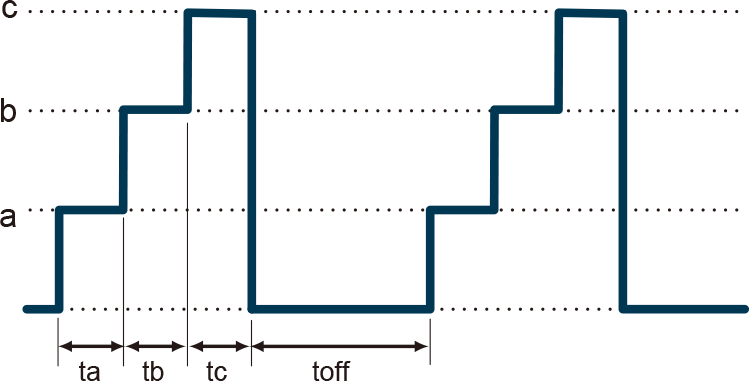
ta, tb, tc, and toff can be set respectively with the range of 0.0 second, 1.0 seconds to 9999 hours 59 minutes 59.9 seconds.
B. Ramp sequence
In this function, the ramp operation is available within the voltage and current settings (or up to 0 V/0 A starting the said values).
It is excellent for increasing or decreasing the voltage and current values gradually. The function can also effectively reduce the load damage caused by overshooting.
* The ramp operation can be set with a range among "both settings of voltage and current value", "voltage setting only", and "current setting only".
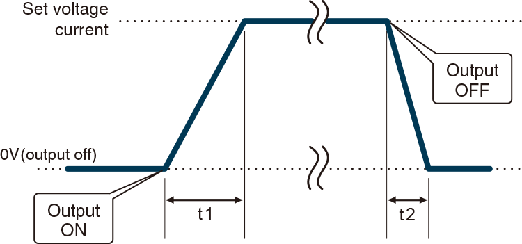
t1 and t2 can respectively be set with the range of 0.0 second, 1.0 seconds to 9999 hours 59 minutes 59.9 seconds.
C. Combination of pulse sequence and ramp
Features of pulse sequence operation and ramp operation can be combined for more convenient operation. In combination with multiple settings, the sequence operation is available by using the voltage and current settings stored respectively in Memory a, b, and c.
Besides setting continuous operation, a specific number of settings is provided. This function allows the voltage or current value to use repeatedly by increasing or decreasing gradually to three different settings, which is really useful for various purposes.

From t1 to t4, from ta to tc, and toff can be set with the range of 0.0 s, 1.0 seconds to 9999 hours 59 minutes 59.9 seconds.
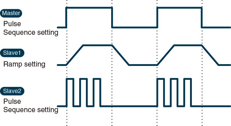
D. Master following
During the pulse sequence and ramp operations in master/slave control, the output signal will be sent to the slave machine.
As the result, the slave machine can have different output status to the master machine.
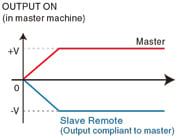
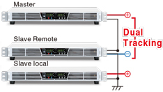
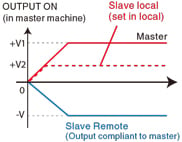
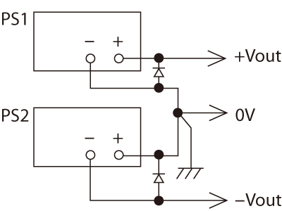
Dual tracking, Multi output
The dual tracking controlling is available by connecting the power to generate the positive and negative outputs in master/slave control. In addition, using the slave local mode, the dual tracking operation can consist of multiple outputs. The positive and negative output voltages (+V and -V) in dual output will output in synchronization with turning on the power of the master machine.
- Download brochre for detailed connection.
- With the output voltage exceeding 250 V, dual tracking is not available.
Dual tracking
Multiple output
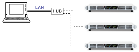
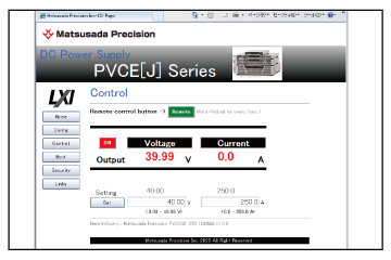
Multiple digital interface *
Equipped with standard LAN, USB(TMC) and RS-485, the function is widely available in various communication systems. Additionally, you can download IVI driver compatible with SCPI command from our website, which is more convenient for the development of control program in programming languages such as LabView, Visual Basic and C#.
- Connection example
- With the following connections, you can readily set up systems like ATE (Auto Test Equipment)


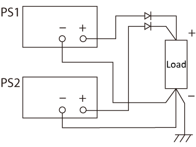
Sink current suppression
When supplying power to loads with capacities like batteries and capacitors, the sink current suppression is used to reduce the reverse current flowing from the load to the unit in order to prevent a voltage drop on the load as the output is OFF or the set voltage is lowered.
NOTE:
It is not possible to stabilize the output by controlling the back currently. In the case of load which has inverse voltage or overrated voltage, such as inductive load or regenerative motor, protect the power supply by adding dummy resister or diode to prevent back current.
Multiple setting
The series has a function to memorize both voltage and current values along with the usual presetting, which is available for a total of three.
So, you do not have to adjust multiple set values each time, which is effective, especially for taking experimental data in experiments or performing manufacturing processes in product inspections.

Master/Slave control
The collective control function is available for connecting up to 15 slave units to a master unit.

- (A) GP-M cable
- A two-meters cable is provided in each unit. If you need a longer cable, please consult with our sales staff.
Key locking
The operation on the front panel can be locked to ensure no operational errors.
(Emergency stop operation using the POWER ON/OFF switch is possible in either mode.)
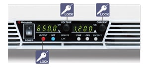
As all the switches are to be locked except LOCK release, it is highly effective in preventing erroneous stop at remote control
- Please note that each of the power supplies connected in parallel has no function for equally keeping the current output of the power supply. If you need a power supply with equal current output, please consult with our sales representatives.
- In master/slave control, the connection must be made between the same models.
External analog remote control
- External Output ON/OFF
Output can be turned ON/OFF by relay or TTL signal. Logic of OUTPUT can be made reverse..
- Remote Sensing
The function ensures the prevention of stability deterioration which could be caused by the voltage drop (Vo-VL) due to resistance (R) of the output wire or contact resistance.
- Remote/Local Switching
As for the output voltage control, output current control, overvoltage protection, and overcurrent protection, the remote/local mode can be individually switched by relay or TTL signal.
- Output Monitor (Voltage, Current)
- Output Control (Voltage, Current)
- Status Output
When you connect an electrical load that gives out high energy pulse output, have the remote connector (TB1) isolated to prevent the damages toward the power supply unit or install -LGob/-LIs/-LRcp option.
Digital Control
The minimum value of each model is the same as the smallest digit display on the front panel
| Digital Controlling |
|
|
|---|---|---|
| Writing |
|
|
| Reading |
|
|
Example of Connection and Operation
Using the same multiple units of PVCE/PVCEJ series, the output voltage and output current can be increased by connecting the outputs in series or parallel.
As to the control, the use of local control or digital master/slave control is recommended.
External I/O control connector (TB1) is connected to the negative output, so do not share the common with more than two units.
Series connection
The total output voltage is up to 250 V.
The output voltage exceeding 250 V is unavailable in series connection.
The output current will be the smallest value.
Parallel connection
Use the same value for voltage setting in parallel connection.
The output current is the sum of each current. In order to prevent damage, set the OVP level of all the power supplies to the maximum.
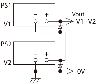
Split connection
+output and –output are available.
With the output voltage exceeding 250V, split operation is not available.
Specifications
Options
- -LGob *1 *2
-
Optical Interface board
With optical communication, isolation control is performed. As complete isolation is performed by means of optical fiber, this enables advance prevention of erroneous operation involved with transient phenomenon caused by surges, inductive lightning, external noise, etc.- -LGob: Optical Interface Board + optical cable 2 meters
- -LGob(Fc5): Optical Interface Board + optical cable 5 meters
- -LGob(Fc10): Optical Interface Board + optical cable 10 meters
- -LGob(Fc20): Optical Interface Board + optical cable 20 meters
- -LGob(Fc40): Optical Interface Board + optical cable 40 meters
- Select the optional optical interface board (-LGob) when using this DC power supply under the following conditions.
-
- Noisy environment including factories (Example: Motors or coils are used near power supplies and loads).
- Using with high voltage floating (more than 250 V).
- Installation distance of two meters or more between the DC power supply and a controller such as a computer, laptop, or Programmable Logic Controller (PLC).
-
The optical communication adapter at the control side should be purchased separately.
For details, click here.
- -LIs *1 *2
-
Galvanic isolation and external analog remote control
The output control signal in the external analog remote control isgalvanically isolated from common (–output terminal).
Floating the control signal in negative output or in series connection is not required. (Withstand voltage from –output is up to 650 V.)
Galvanic Isolation from common (–output terminal) is also applied to the following signals and switches.Output control Constant voltage: External control voltage 0 to 5 V or 0 to 10 V
Constant current: External control voltage 0 to 5 V or 0 to 10 VMonitor output Constant voltage: 0 to 5 V or 0 to 10 V
Constant current: 0 to 5 V or 0 to 10 VOther functions External output ON/OFF
Interlock (This function does not satisfy UL and CE safety interlocks.)
Voltage mode switching of Local/Remote
Current mode switching of Local/Remote
- -LRcp *1 *2
-
Galvanic isolation and external analog remote control of current The external analog signal is galvanically isolated. The control of current is provided instead of voltage.
-LRcp option has a stronger feature against noise involving to the control signals.Output control Constant voltage: External control current 4mA to 20 mA
Constant current: External control current 4mA to 20 mAMonitor output Constant voltage: 4mA to 20 mA
Constant current: 4mA to 20 mAOther functions External output ON/OFF
Interlock (This function does not satisfy UL and CE safety interlocks.)
Voltage mode switching of Local/Remote
Current mode switching of Local/Remote
- -L(Mc0.5), -L(Mc0.15)
-
Change of communications cable
The CO-M cable length can be selected from 0.5 meters or 0.15 meters. (Please choose one of the two cables described above.)
- -L(3P), -L(1P)
-
Change of phase number in AC input
To see for details, please download the datasheet.
- -L(400V)
-
Input voltage 400 Vac ±10%
(Soon to be available for 3.2 kW to 5.5 kW models)
Contact our sales representatives for details.
- These options cannot be selected simultaneously. Only a single option can be selected.
- When selecting these options, Multiple Digital Interface function is not available.
How to Order
When ordering, add Option No. in the following order How to order by alphabet to Model No.
Example:
PVCE6-310-LGob(Fc40)(3P)
PVCE10-80-LIs(Mc0.5)
PVCEJ350-2.2-LRcp(Mc0.15)
Accessories
Cable
Select an appropriate AC input cable according to your operating environment and region.
Please note that other than AC input cables that correspond to the following are to be prepared by customers.
| Standard (075 kW to 0.81 kW models) (For Japan or North America) |
CABLE TYPE8 |  |
 |
125 V/15 A | 2.5 meters Fixed length |
|---|---|---|---|---|---|
| Sold separately (075 kW to 0.81 kW models) (For Europe) |
CABLE TYPE3 | |
 |
250 V/10 A | 2.5 meters Fixed length |
| Sold separately (1.3kW to 2.5 kW models) (For Japan or North America) |
CABLE TYPE5 |  |
 |
300 V/25 A | 2.5 meters |
| Sold separately (2.5kW to 5.5 kW models) (For Japan) |
CABLE TYPE6 |  |
 |
600 V/25 A | 2.5 meters |
| Sold separately (10 kW to 15 kW models) (For Japan) |
CABLE TYPE7 |  |
 |
600 V / 75 A | 10 meters |
Digital Interface
Enable digit control via LAN/USB/RS-232C/RS-485/GPIB as well as one control with master/slave.
Adapter for digital interface
To use the digital interface, you need to prepare an digital interface adapter separately. The following interface adapters are available according to the communication method of your controller port.
- CO-E32m: Adapter for LAN
- CO-U32m: Adapter for USB
- CO-MET2-9: Adapter for RS-232C (9 pin)
- CO-MET2-25: Adapter for RS-232C (25 pin)
- CO-MET4-25: Adapter for RS-485 (25 pin)
- CO-G32m: Adapter for GPIB
Example of communication with a digital adapter

Optical isolation adapter
To use the optical interface, you need to prepare an optical interface adapter separately. The following interface adapters are available according to the communication method of your controller port.
- CO-E32: Adapter for LAN
- USB-OPT: Adapter for USB
- CO-OPT2-9: Adapter for RS-232C (9 pin)
- CO-OPT2-25: Adapter for RS-232C (25 pin)
- CO-OPT4-25: Adapter for RS-485 (25 pin)
- CO-G32: Adapter for GPIB
Example of communication with optical fiber

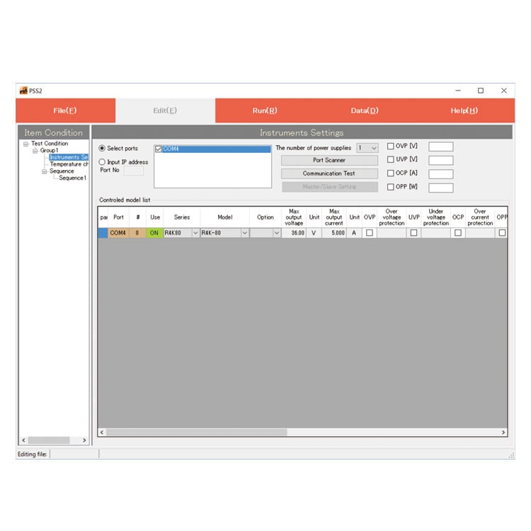
Application software for power supplies and electronic loads
PSS2en series
PSS2en is the dedicated software which can actuate various power supplies, electronic loads and digital controller for power supplies manufactured by Matsusada Precision Inc. with simple set up.
It is the perfect for the aging test, the burn-in test and the withstand voltage test for electronic parts, and for the endurance test, intermittent/continuous operation test or various simulation test for electric component of automobile.
For details, refer to PSS2en page.

Dimensions
Download
If you are unable to download a file
Please try the following solution.
- Please press Ctrl+F5 to clear the cache of your web browser and try again.
- Please restart your web browser and log in again to try again.
- Please change your web browser to another browser and try again.
- Restart the computer and try again.
- Please try again on a different computer.
-
PVCE series Datasheet
Date: 2023-07-24 rev.13
PDF (3,122 KB)
-
DC POWER SUPPLIES SELECTION GUIDE
Date: 2023-12-06 rev.00
PDF (1,202 KB)
-
How to Use DC Power Supplies
Date: 2024-03-05 rev. 08
PDF (1,467 KB)

-
PVCE/PVCEJ series Basic Instruction Manual (Both Japanese and English)
Date: 2020-09-10 rev 1.0
PDF (1,034 KB)
-
PVCE/PVCEJ series Instruction Manual
Date: 2020-09-01 rev0.0
PDF (4,029 KB)
-
PVCE/PVCEJ series Interface Manual
Date: 2020-11-19 rev.0.0
PDF (1,820 KB)
-
PVCE/PVCEJ series IVI Driver
Date: 2020-12-22 rev. 00
ZIP (8,556 KB)

-
PVCE series Outline Drawing (DXF, PDF)
Date: 2020-06-01
zip (14,784 KB)
The account registration is necessary for downloading
-
PVCE series Datasheet
Date: 2023-07-24 rev.13
PDF (3,122 KB)
-
DC POWER SUPPLIES SELECTION GUIDE
Date: 2023-12-06 rev.00
PDF (1,202 KB)
-
How to Use DC Power Supplies
Date: 2024-03-05 rev. 08
PDF (1,467 KB)
-
PVCE/PVCEJ series Basic Instruction Manual (Both Japanese and English)
Date: 2020-09-10 rev 1.0
PDF (1,034 KB)
-
PVCE/PVCEJ series Instruction Manual
Date: 2020-09-01 rev0.0
PDF (4,029 KB)
-
PVCE/PVCEJ series Interface Manual
Date: 2020-11-19 rev.0.0
PDF (1,820 KB)
-
PVCE/PVCEJ series IVI Driver
Date: 2020-12-22 rev. 00
ZIP (8,556 KB)
-
PVCE series Outline Drawing (DXF, PDF)
Date: 2020-06-01
zip (14,784 KB)
In this website, we provide only the latest version of information including instruction manuals as of our products. Therefore, the newest versions of manuals on the website might be not same as the ones of products you purchased in the past.